Installation instructions
Before you start
The Ecoexitblade is intended for recessed mounting in a ceiling. The mains connection is via a standard
Australian flex and plug. A standard 10A single surface socket outlet plug base or equivalent is required in
the celling cavity close to the intended location of the fitting. A surface mount kit (part number
Blade configuration
1. Identify the location for the fitting and determine the type of exit display required - exit left, exit
right or straight-ahead. Note that the Blade assembly is supplied configured for straight ahead –
double sided.
2.
unwanted pictogram out the top of the assembly and insert the required pictograms and diffusers.
3. Make sure the edge of the diffuser inserts with the notched corners goes in with the notches
downward. The top of the pictograms and inserts should be flush with the top of the Blade
assembly. A fingernail slid along the bottom of the Blade assembly will help the inserts slide fully
into the bottom edge of the frame.
Power up
1. After installation switch on the mains power to the unit and test. Once powered up the fitting will
light up and the red LED indicator should be on – indicating the battery is connected and charging.
2. Press the test button located on the fitting near the red LED. Hold the test button in for a few
seconds and observe the red LED go off while the main light remains on. The transition of the
mains light from mains to emergency is seamless and is only indicated by the red LED.
3. Carry out a commissioning test as per AS/NZS 2293.2.
Battery Replacement (and product removal)
1. Turn off the mains supply to the fitting. If the fitting is functioning correctly the lamp will remain lit
but the red LED should now be off.
2. Insert a large flat head screwdriver under the edge of the Base plate and lever the plate away from
the ceiling far enough to insert your fingers in the gap. Pull the fitting down from the ceiling. Take
care to avoid having your fingers near the mounting springs as they will snap back to the plastic
with some force.
3. Unplug the fitting from the mains socket.
4.
battery and replace with part 03-01325.
5.
6.
battery before it will be capable of a full length discharge again.
7. Carry out a commissioning test as per AS/NZS 2293.2.
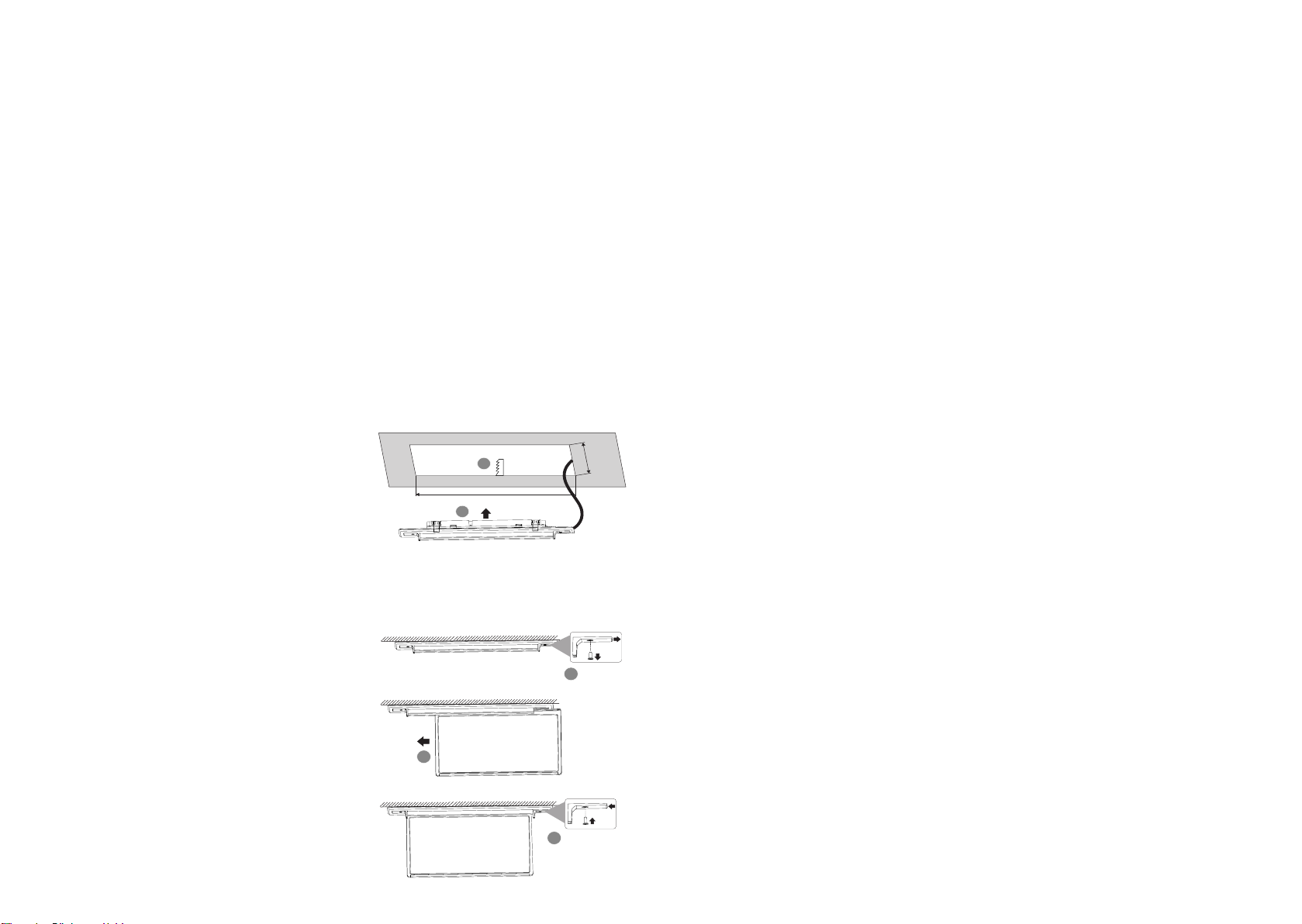
Base installation
1. Ceiling cut-out is 370 x 90 mm. Cut the opening
in the ceiling and mark the centre of the long
side of the cutout to aid in centering the
assembly.
2. Locate the mains socket and plug in the Base
assembly. Identify which side the test switch
and LED should sit then insert the Base
centrally into the cutout by engaging the
mounting springs on one side. With your
thumbs fold back the other two mounting
springs sufficient to engage the cutout then let
the Base snap into position.
Blade installation
1.
Base by removing the retaining screw.
2. Slide the Blade assembly into the extrusion.
3.
24 hours battery charge is recommended to allow the fitting battery to reach full capacity, ie: prior
to a discharge test. As the installer, it is your responsibility to conduct the initial discharge testing
of the installed fitting. Refer to AS/NZS 2293.2.
Testing precautions
Once the fitting is permanently connected to the mains supply, a commissioning discharge test as
required in AS/NZS 2293.2 must be carried out.
Allow 24 hours for the battery to fully charge prior to conducting this test, presently (at the time of
hours for their commissioning test and for not less than 90 minutes thereafter (it is required that 6
and enter them into the building emergency services logbook or via other recording methods as
allowed by AS/NZS 2293.2.
Construction sites
Continuously switching off the mains power supply that is connected to emergency light fittings
during the construction phase of an installation will cause these fittings to discharge and charge their
batteries many times over a short period; this can shorten life of the battery. ABB does not
recommend such practices and may not honour the warranty on batteries when they are subjected to
such harsh operating conditions. Emergency light fittings are designed to be discharge tested once
every 6 months as per AS/NZS 2293.2, subjecting the product to repeated discharge or charge cycles
is regarded as an abuse of the fittings.


