ABB SACO 16D3 Parts list manual

SACO 16D3
Annunciator unit
User´s manual and Technical description

2
1MRS 751354-MUM EN
Issued 99-09-08
Version A (replaces 34 SACO 16D3 EN1)
Checked EP
Approved EP
Data subject to change without notice
SACO 16D3
Annunciator unit
Table of contents Features ........................................................................................................................................ 3
General ......................................................................................................................................... 3
Area of applications ...................................................................................................................... 3
Description of functions ............................................................................................................... 4
Introduction ........................................................................................................................... 4
Mechanical construction .........................................................................................................5
Field contact circuits ............................................................................................................... 6
Alarm channel functions .........................................................................................................6
Visual alarm indication ........................................................................................................... 8
Standardized operational sequences ........................................................................................ 8
First-out indication ............................................................................................................... 10
Event register ........................................................................................................................ 10
Event register for the serial communication .......................................................................... 11
Auxiliary outputs .................................................................................................................. 12
Group alarm reflash signals ................................................................................................... 13
Audible device output ...........................................................................................................14
Self-supervision output .........................................................................................................15
Interlockings ......................................................................................................................... 16
Serial communication interface............................................................................................. 18
Synchronizing of the blinking sequence ................................................................................ 18
Programming ........................................................................................................................ 19
Auxiliary power supply system .............................................................................................. 19
Application ................................................................................................................................. 20
Mounting ............................................................................................................................. 20
Terminals and wiring ............................................................................................................21
Start-up ................................................................................................................................. 22
Operational test .................................................................................................................... 22
Legend plate ......................................................................................................................... 22
Changing the mode of operation for relays on SWOM 16A1 .............................................. 23
Selection of output contact mode for output relay on SWIM 2A1 ....................................... 24
Operation instructions ..........................................................................................................25
First-out alarm indication ..................................................................................................... 26
Event sequence register .........................................................................................................27
Programming ............................................................................................................................. 28
Programming technique ....................................................................................................... 28
Programming push-buttons .................................................................................................. 30
Channel related parameters................................................................................................... 30
Selection of channel input delay...................................................................................... 30
Selection of channel resetting delay ................................................................................. 30
Selection of field contact type or pulse counter ............................................................... 31
Selection of channel-specified indications ....................................................................... 31
Configuration of pumping supervision ........................................................................... 31
Configuration of reflash group alarms ............................................................................. 31
Module related parameters.................................................................................................... 32
Selection of mode of operation for the reflash output relays ........................................... 32
Selection of interlocking configuration ........................................................................... 33
Selection of annunciator SPA bus slave address .............................................................. 33
Selection of alarm sequence type ..................................................................................... 34
Selection for the serial communication port .................................................................... 34
Parameter selection key .........................................................................................................35
Parameter chart ..................................................................................................................... 36
Channel interlocking scheme ................................................................................................ 37
Remote information to and from the alarm annunciator ...................................................... 38
Event codes ........................................................................................................................... 42
Technical data ............................................................................................................................ 42
Testing ....................................................................................................................................... 44
Maintenance and repair .............................................................................................................. 44
Exchange and spare parts ............................................................................................................ 45
Ordering information ................................................................................................................. 45

3
Features SACO 16 D3 is a self-contained microprocessor
based multi channel alarm annunciator unit
16 contact operated on/off alarm or pulse count-
ing channels per unit
16 signal follower relay outputs + two group
alarm outputs or alternatively 16 group alarm
outputs
Relay output for audible alarm and self supervi-
sion
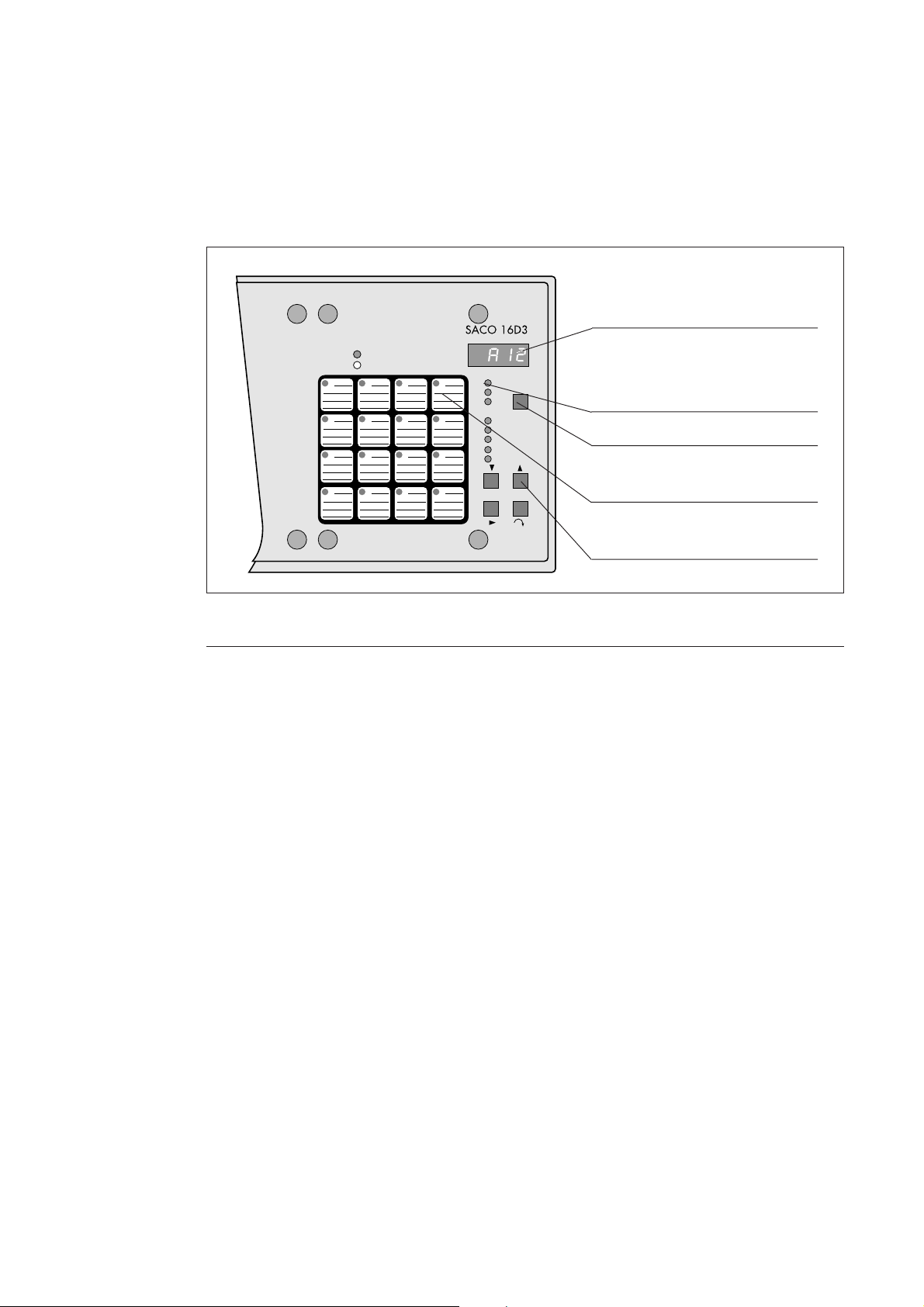
LEDs for visual alarm indication
Fully programmable by means of push-buttons
on the front panel or via the serial communica-
tion interface
Numerical display for first out alarm indication,
event sequence reporting and programming
Event register for the 50 latest events
Serial communication interface for easy con-
nection of the annunciator unit to a monitoring
and/or control system.
Improvedsystemreliability backed upbyasophis-
ticatedself-supervision functioncomprisingboth
hardware and software watchdog functions
High immunity against electrical interference
and an enclosure to IP 54 when panel mounted
General The alarm annunciator unit type SACO 16D3
is a part of the integrated substation secondary
equipment system SPACOM.
The on/off annunciator unit is a fully self-
contained compact microprocessor based de-
vice suitable for use as stand-alone annunciator,
but also as data acquisition, recording or control
unit, either stand-alone or integrated into a
system.
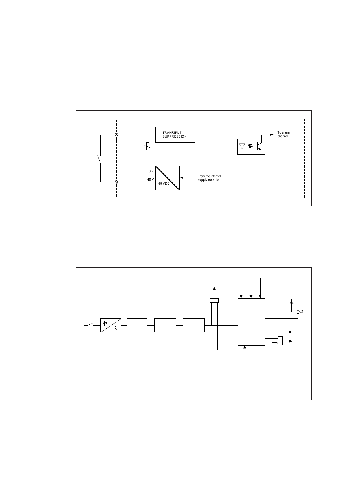
The annunciator unit is provided with 16 chan-
nels for operation from NO or NC field con-
tacts. The unit is furthermore provided with
four auxiliary output relays, one for control of
an audible device (horn, buzzer etc.), one is
controlled by the internal self-supervision sys-
tem and two for general retransmission of indi-
vidual or group alarm signals. The unit is also
provided with two control inputs for external
acknowledge and reset functions. The alarm
annunciator unit is fully self-contained includ-
ing an integral power supply unit generating the
internal supply voltages as well as the external
field contact voltage, which also is used in the
external acknowledge/reset circuits. Thus no
separate power units are needed for the field
contact circuits.
The unit is provided with 20 output relays for
signal transfer. Two of these relays are used as
group alarm outputs, one is to be used for
controlling an audible device and the other for
the internal supervision system. The other 16
output relays can be used either as input signal
following outputs or as group alarm outputs.
The microprocessor module is a standardized
100 mm x 160 mm Euro-card printed circuit
board (PCB) which also functions as the basic
element in large alarm annunciator systems
mechanically designed according to the 19 inch
rack and cabinet system (SACO 64D4).
The modern microprocessor technology used in
the SACO system offers new features which not
only extend the conventional area of application
for alarm annunciator systems but also increase
the reliability of the annunciator systems. The
most significant feature of the new annunciator
system is the outstanding system flexibility. The
annunciator is truly field programmable by
means of push-buttons on the front panel, or
from a PC via the serial communication, for easy
selection of a proper operational scheme and
suitable parameter values in the intended appli-
cation.
Area of
application
The annunciator unit SACO 16D3 has been
developed and manufactured to meet the most
demanding specifications regarding reliability
in operation and immunity against interference
which can be expected from a modern annun-
ciator system for use in:
- electric power plants and substations
- industrial plants and processes
- marine vessels and off-shore installations
- technical installations in buildings
- water treatment plants, etc.
Furthermore the annunciator system can be
used in any conventional application where
there is a demand for a continuous supervision
or monitoring of a number of contacts to pro-
vide an immediate fault recognition, fault iden-
tification and a visual/audible alarm in order to
call attention to an abnormal process condition
or as a pulse counter for change of state of a
process parameter under normal process condi-
tions.

4
Description of
functions
Introduction
The annunciator unit SACO 16D3 is a flexible
and versatile annunciator package comprising
16 input alarm channels. Its main purpose is to
supervise a given process and to call attention to
abnormal process conditions by the use of indi-
vidual visual LED indicators and a common
audible device. The annunciator system can also
be connected to an event recorder system, by
means of which printed records with channel
identification, date and time, are obtained when-
ever a change in the state of an alarm channel
occurs.
The basic functions of the annunciator unit are
illustrated in the block diagram below.
The alarm channel inputs are connected to the
field contacts. The field contacts, i.e. the output
contacts of the devices sensing the process con-
dition can be of the normally open (NO) or the
normally closed (NC) type.
The central unit continually compares incom-
ing channel information with previously stored
information. When a change of state has been
detected, the alarm channel is activated and if
the situation persists for a longer time than the
specified channel input delay time, the event
will be registered. The visual indicators and the
auxiliary output relays respond to the situation
according to the functional program they have
been given.
The annunciator unit can be acknowledged and
reset with a push-button on the front panel or by
means of external remote push-buttons.
The annunciator unit comprises an internal
event register. The unit is provided with a serial
communication interface and thus it can be
connected to a local data collector, e g a SRIO
500M/1000M, by means of a serial communi-
cation link. The information stored in the event
register of the annunciator unit can be read out
via the serial communication link.
Internal supply
SWIM 2A1
Alarm channels 1...16
1216
Supply
1 2
16
16
Flatcable connector
Serial communication
SWOM 16A1
1216
SPA-buss
connection
Self-supervision and
audible alarm output
Group reflash
outputs
12
Remote
reset/ackn.
SACO 16D3
Relay outputs
1...16
Fig. 1. Block schematic diagram for the annunciator unit SACO 16D3.

5
Mechanical
construction
The annunciator unit is composed of standard-
ized 100 mm x 160 mm "Euro-card" plug-in
modules.An annunciatorunit typeSACO 16D3
consists of the following modules:
- a power supply module type SPGU 240A1 or
SPGU 48B2
- an Input/Output module type SWIM 2A1
- an alarm annunciator module type SWPM
3A1
- an output relay module type SWOM 16A1
The enclosure of the annunciator module con-
sists of an extruded aluminum profile to which
the connection module SWCM 11A1 has been
fixed to form the mounting case. The connec-
tion module comprises the plug-in PCB con-
nectors and the screw terminals to facilitate all
external connections. The connection module
also comprises a 48 V dc power unit for voltage
supply to the field contact circuits.
The annunciator unit is intended for flush
mounting. The depth behind the panel can be
reduced by 40, 80 or 120 mm by using a raising
frame.
The cast aluminum alloy mounting frame is
stove-finished with a beige semi gloss carbamide
resin paint and provided with a rubber gasket
which provides a degree of protection by enclo-
sure to IP 54 between the mounting case and the
panel.
The mounting case is also provided with a glass-
clear UV-stabilized polycarbonate lid with a
sealable locking screw. The lid also has an IP 54
classification when closed with the finger screw.
The screw terminal blocks to facilitate all input
and output wire connections are located on the
back of the mounting case. One or two max. 2.5
mm2conductors can be connected to each
terminal. No terminal lugs are needed. A con-
nection diagram is shown on one of the sides of
the case.
FAULT
ON
Connection module
SWCM 3A1
Mounting case
Power supply module SPGU 240A1 or SPGU 48B2
Output relay module SWOM 16A1
Lid
Front panel
Fig. 2. Plug-in modules of the annunciator unit SACO 16D3.
Input/output module SWIM 2A1
Alarm annunciator
module SWPM 3A1

6
Field contact circuits The electrical contacts of the devices sensing the
process condition must be potential-free while
the annunciator unit itself generates the 48 V dc
field contact voltage. This specification also
applies to the remote control inputs.
The power unit supplying voltage to the field
contacts also provides a full galvanic isolation
between the field contact circuits and the elec-
tronic circuits of the annunciator unit it self as
well as the system earth. The channel inputs are
provided with transient suppression circuits and
input voltage limiters.
The alarm channels can be individually pro-
grammed for operation from normally closed
(NC) or from normally open (NO) contacts.
The annunciator is provided with an integrated
fieldcontact voltagesupervision function.When
a fault is detected the LED indicator marked
"FAULT" on the front panel is switched on and
internal supervision output relay operates. The
fault message can also be transmitted over the
serial communication link to the higher system
levels.
TRANSIENT
SUPPRESSION To alarm
channel
48 VDC
From the internal
supply module
0 V
48 V
Field
contact
Galvanic isolation
Fig. 3. Principle of alarm channel input.
Alarm channel
functions
An alarm channel is composed of a number of
functional blocks illustrated below. The lists of
variables underneath some of the blocks indi-
cate that a certain parameter can be selected
from a set of given values, i.e. the parameter can
beprogrammed. Theselectedparameter isshown
in the numerical display when called up during
the programming.
Fig. 4. Block schemating diagram for an alarm channel.
SEQUENCE
LOGICS
Reflash B
&Reflash A
Interlocking
output (0) Ack. Reset
1
Alarm indicator
Audible alarm
Reflash A
interlocking
input (1)
Channel
interlocking
input (2)
FIELD
CONTACT
SELECTION INPUT DELAY RESET DELAY
48 V
Field
contact
Galvanic isolation
and transient
suppression
0 = NO field contact
1 = NC field contact
2 = NO field contact,
no return function
3 = NC field contact,
no return function
4 = NO and NC field
contact
5 = pulse counter,
counts on closing
function
6 = pulse counter,
counts on opening
function
7 = pulse counter,
counts on both
closing and opening
function
0 = 5 ms
1 = 20 ms
2 = 100 ms
3 = 1 s
4 = 5 s
5 = 20 s
6 = 60 s
7 = 160 s
0 = 5 ms
1 = 20 ms
2 = 100 ms
3 = 1 s
4 = 5 s
5 = 20 s
6 = 60 s
7 = 160 s
-
0 = sequence 0-4
1 = sequence 0-4,
audible alarm
also at dis-
appering alarm
2 = field contact
following
Silence

7
After the galvanic separation and the transient
suppression the incoming field contact signal is
analyzed and identified in respect of signal type.
Seven input signal types are specified:
0 = signal from normally open contact, with
return function
1 = signal from normally closed contact, with
return function
2 = signal from raising edge only
3 = signal from falling edge only
4 = signal from raising and the falling edge
5 = pulse counter, counts by contact closing
6 = pulse counter, counts by contact opening
7 = pulse counter, counts by contact opening
and closing
The input signal types 2, 3 and 4 are usually
selected when event recording is used. For ex-
ample the signal indicating that a circuit breaker
has tripped is noticed and registered with its
raising edge only.
The pulse counter is used only when the data is
transferred to a higher level system. The pulse
counter channels sequence logic is to be set to
signal following without blinking and audible
alarm functionality (S4 = 2). The reflash relays
connected to the pulse counter channels are to
be configured as ISR, Impulse Shaping Reflash
(S1 or S2 = 2).
Thechannels configuredaspulse counterscounts
pulses up to 3 Hz. The capacity of the counter
is 0...29999. The counter is freely presettable
withinthis range.Whenthe pulse counterreaches
29999 it starts over again from 0.
The counter can be read and set only via the SPA
bus with the channel specific parameter V5.
When the parameter V5 is read the present value
of the pulse counter is received, when written the
preset (start) value for the pulse counter is given.
The counters memory circuit has no battery
backup, hence the stored values are lost if the
auxiliary power drops off and the counter starts
over again from 0 or its preset value when the
auxiliary power returns.
When a change of status has been detected for an
incoming field contact signal and the new status
exceeds the channel input delay in duration, the
operation sequence memory is activated.
The channel input delay can be selected from a
set of eight alternative values from the front
panel:
0=5 ms
1 = 20 ms
2 = 100 ms
3=1s
4=5s
5 = 20 s
6 = 60 s
7 = 160 s
8 = another value, which is programmed via the
serial interface
Via the serial interface the channel input delay
can be freely programmed. Refer to the param-
eter list in the end of this manual (S1).
If the change-of-status of a field contact signal
means that the signal returns to normal, the
channel reset delay time must be exceeded be-
fore the change is registered. The delay time
alternatives are the same as those for the input
delay but the channel reset delay times are
selected separately (S2).
When the operation sequence logic circuits are
activated, the visual alarm displays start func-
tioning according to the programmed opera-
tional sequence (flash sequence). The most suit-
able of five standard operational sequences is
chosen by programming. All changes of status of
the incoming signals are stored in the event
register irrespective of the selected operational
sequence for the visual alarm displays.
The sequence memory is acknowledged/reset in
the following order:
SlLENCE = resets the audible alarm
ACKNOWLEDGE = indicates recognition of
an alarm
RESET = returns the channel to
the normal state
The alarm channels each generate two reflash
signals A and B which can be linked to the
auxiliary reflash output relays, for details please
refer to section Configuration of reflash group
alarms on page 31.
Each alarm channel is also provided with two
interlocking signal inputs and one interlocking
signal output. The interlocking signal inputs/
outputs are:
0 = interlocking signal output. Can be con-
nected to the other channels
1 = interlocking signal input. Blocks the reflash
signal A
2 = interlocking signal input. Blocks the whole
alarm channel, returns as acknowledged
alarm
3 = interlocking signal input. Blocks the whole
alarm channel, returns as a new alarm
The interlocking signal output is also always
activated by an interlocking signal input being
activated in the same channel.

8
Visual alarm
indication
The state of the alarm channel is indicated by
super-bright LEDs. A legend plate of transpar-
ent film is inserted in a slot at the edge of the also
transparent plastic overlay. For more informa-
tion, see section "Legend plate", page 22.
The first-out indication is accomplished with
the four digit display on the front panel. The
information stored in the event register can also
be displayed on the digital display.
Acknowledge and reset is done with a push-
button located on the plastic cover on the front
of the unit or with two external push-button.
The reset indicator LEDs on the front panel
marked SILENCE, ACK, RESET/TEST shows
which of the actions is to be performed. The
reset sequence depends on the operational se-
quences.
FAULT
ON
Four-digit seven-segment display
Reset indicator LEDs
SILENCE
ACKNOWLEDGE
RESET/TEST
Acknowledge/Reset push-button
Channel window with indicator
LED and legend text
Event register step-by-step
read-out push-button
Fig. 5. Alarm indicators and push-buttons of the annunciator unit SACO 16D3.
Standardized
operational
sequences
The annunciator unit is supplied with five stand-
ardized field-selectable operational sequence al-
ternatives of which the most adequate one for a
certain application is selected. The operational
sequences are:
0 = ISA A, automatic reset
1 = ISA A-1, automatic reset, separate reset of
audible alarm
2 = ISA M-1, manual reset, separate reset of
audible alarm
3 = ISA R-1, manual reset, separate reset of
audible alarm, visual ringback on return
4 = DIN 19235, manual reset after return to
normal if acknowledged while alert, visual
ringback on return if acknowledged before
return to normal
The above operational sequences are common
to all the 16 channels. However the sequences
can be altered on a per-channel basis according
to the following:
0 = indicationsaccording totheselected sequence
1 = indicationsaccording totheselected sequence
but including audible alarm also on return.
Valid only for sequences ISA R-1 and DIN
19235
2 = field contact following indication without
audible alarm
The acknowledge/reset operations required are
determined by the annunciator unit itself and
the acknowledge/reset operation being asked
for is pointed out with the indicator LED. The
annunciator unit is provided with two external
control inputs, one for remote resetting of the
audible device and an other for remote acknowl-
edge/reset of the alarm channels.
NOTE!
Theacknowledge/reset push-buttonon thefront
panel also operates as a visual display test but-
ton. The test is accomplished by pressing the
acknowledge/ reset test button continually for
approximately 1 second which causes all LED
indicators to light up and the digital display to
show 8888. The visual displays can not be tested
if an alarm channel is unacknowledged or not
reset. Pressing the test button for approximately
15 s activates the self-supervision auxiliary out-
put relay and the FAULT LED.

9
Automatic reset
ISA A
ON
OFF
ON
OFF
ON
OFF
ON
OFF
ON
OFF
ON
OFF
ON
OFF
ON
OFF
ON
OFF
ON
OFF
ON
OFF
ON
OFF
ON
OFF
ON
OFF
ON
OFF
ON
OFF
ON
OFF
ON
OFF
ON
OFF
ON
OFF
ON
OFF
Field contact
Acknowledge
Reset of audible output (Silence)
Audible output
Field contact
Visual alarm indicator
Acknowledge
Audible output
Field contact
Visual alarm indicator
Acknowledge
Reset of audible output (Silence)
Audible output
Reset
Field contact
Visual alarm indicator
Acknowledge
Reset of audible output (Silence)
Audible output
Reset
Field contact
Visual alarm indicator
Acknowledge
Reset of audible output (Silence)
Audible output
Reset
Automatic reset, separate reset of audible output
ISA A-1
Manual reset, separate reset of audible output
ISA M-1
Manual reset, visual ringback and separate reset of audible output
ISA R-1
Manual reset, visual ringback if acknowledge is done before the alarminput returns
to normal state, separate reset of audible output
DIN 19235
ON
OFF
ON
OFF
ON
OFF
ON
OFF
ON
OFF
ON
OFF
Visual alarm indicator
Fig. 6. Selectable alarm sequences.

10
First-out indication The annunciator unit is provided with a first-
out indication feature. The alarm channel which
operates first is indicated in the digital display
with a letter A and the channel number. The
first-out indication always relates to the first
incoming alarm after an annunciator acknowl-
edge/reset being performed. The first-out indi-
cation can be reset with the acknowledge/reset
push-button.
Channel 1
Channel 2
Channel 3
Channel 16
First-out
alarm
memory
Reset
Digital display
Not used
Type of event
A = incoming alarm
Channel number
1...16
Fig. 7. Principle of the first-out alarm indication.
Event register For evaluating of disturbances, the alarm an-
nunciator unit has been provided with an event
register, which enables the incoming and disap-
pearing alarms to be read out. The register holds
9 events which can be read out on the digital
display step by step using the push-button ↑.
The latest (youngest) information, i.e. address
No 9, is read out first and then the events are
represented in the display one by one until
address No 1, which represents the oldest infor-
mation, is reached.
Chronological order
Decimal point indicates first-
out alarm after previous
acknowledge
Type of event
A = incoming alarm
- = disappering alarm
- - - - = acknowledge
Channel number
1...16
Channel 1
Channel 2
Channel 3
Channel 16
Event
register
Acknowledge
Digital display
Youngest event
The information of the event
register is read out with the
push button
Fig. 8. Operating principle of the event register.

11
Event register for the
serial communication
The annunciator unit incorporates a separate
event register which contains information on
the type of event and the channel number in-
cluding a synchronous time stamp. This enables
a higher level system to read out events from the
annunciator over the SPA bus serial communi-
cation. The event register holds 50 events. The
time stamps are relative and the time span is
max. 60 s. The clocks of the interconnected
units are synchronized, generally once per sec-
ond, by the higher level system (the SPA bus
master). The time resolution between the chan-
nels is 5 ms.
The annunciator unit also includes a channel
matrix register which operates in parallel with
the event register and in which each channel
corresponds to one bit. If a channel is activated
during an overflow situation of the even register,
the corresponding bit in the matrix register is
activated.
Fig. 9. Event registration in SPACOM systems.
Overflow
Overflow
Time Slave Channel Code
2
1
500
Adding of
users text
Event register
Clock
SPA-bus
Synchronization
SRIO
Printer
Host system
Time Slave Channel Code
Channel CodeTime
Events
Clock
0 - 60 s
SACO alarm module
Event
register
Overflow
1234
5678
91011
14 16
Event overflow
matrix register
SPA-bus
Clock
0 - 60 s
Time
1
2
3
.
.
.
.
n
Channel Code
Events
SPA-bus
SPACOM protective relay module
Event
register
12
13 15
Time marking: year, month,
day, hour and minute
1
2
3
.
.
.
.
.
.
.
48
49
50

12
Auxiliary outputs The annunciator includes four auxiliary output
relays. Two output relays act as group alarm
reflash output elements, one auxiliary output
relay is dedicated for control of an audible device
and one relay acts as an auxiliary output element
for the internal self-supervision function.
Further the annunciator contains a 16-channel
output relay module, which can be used for
group alarm purposes or for input signal follow-
ing reflashing. The connection is changed by
means of two band cables, which becomes acces-
sible after removing the front panel. The group
alarm connector is marked "GROUP ALARM"
and the connector of the reflash signal cable is
marked "SIGNAL FOLLOWER".
In the group alarm position the first two relays
on the relay card operate in parallel with the
fixed group alarm relay outputs.
When the relays of the output relay module are
used as pure input signal following output ele-
ments, the output relays completely follows the
input field signal. Any possible programmed
channel input or output delay is in this case
neglected.
Fig. 10. Principle diagram of reflashes.
1
Grouping
16
Group alarm 16
Group alarm 1
2
Group alarm 2
Field contact 1 Alarm
channel 1
Field contact 16 Alarm
channel 16
A
B
A
B
Field contact 2 Alarm
channel 2
A
B
3
Group alarm 3
Field contact 3 Alarm
channel 3
A
B
Selection of
reflash mode
for relay 1
Selection of
reflash mode
for relay 2
Selection of
reflash mode
for relay 16
Selection of
reflash mode
for relay 3
Flat-
cabel
Flatcabel
Reflash output 1
Reflash output 2
Relay output 1
Relay output 2
Relay output 3
Relay output 4
Relay output 15
Relay output 16
SWOM 16A1
SWIM 2A1

13
Group alarm reflash
signals
Each alarm channel generates two reflash output
signals, A and B, which can be freely linked to the
two reflash output relays to form two group alarm
reflash functions. The two group alarm reflash
output relays can be given one of the following
modes of operation selectable by programming,
separately for both of the output relays:
0 = FCFR, Field Contact Following Reflash
1 = AACR, Acknowledge Action Controlled
Reflash
2 = ISR, Impulse Shaping Reflash
3 = FCFR + ISR, Field Contact Following
Reflash with a 300 ms interruption of the
reflash signal any time a new alarm signal
joins in an already active group alarm bunch
4 = FCFR + AACR, Field Contact Following
Reflash and Action Controlled Reflash (se
figure below)
Channel input delays Channel reset delay
Alarm 1
Alarm 2
Acknowledge
Signal following
Alarm memory following
Pulse type
Signal following with break
FCFR + AACR
Fig. 11. Principle diagram for the different reflash signal types. The alarm signals 1 and 2 are grouped
to the same group alarm reflash signal.
NOTE! The reflash signals are always accompa-
nied by a certain basic delay. The basic delay
time depends on the number of incoming alarm
signals per time unit and on the number of
internal interlocking levels in use. The basic
time delay of the reflash signal is 70 ms if only
one alarm signal is received within a time period
of 200 ms and if no interlockings are used.

14
Audible device
output
Generally the relay output for control of an
audible device operates if one of the 16 alarm
channels is activated. Every channel can also be
separately programmed to deliver an audible
ringback when the alarm channel returns to
normal state. If an alarm channel has been
programmed for a sequence providing a field
contact following visual indication only, no
audible alarm will be generated, please refer to
"Standardized operational sequences" on page 8.
The audible device can be silenced by means of
the acknowledge/reset push-button or by means
of an external control signal applied to the remote
silence control input (17) of the annunciator
unit.
An incoming alarm signal, for which only the
audible alarm has been silenced but the alarm
signal has not been acknowledged nor reset, will
not produce a new audible alarm if the field
contact starts "pumping".
Channell 1
Channel 2
Channel 3
Channel 16
Audible
alarm
memory
Reset of audible
output
(Silence)
Audible device
relay output
Fig. 12. Principle diagram for the audible alarm.

15
Self-supervision
output
The annunciator unit is provided with extensive
self-supervision functionality which, in case of
an internal fault or if an internal malfunction is
detected, causes an operation of the self-super-
vision auxiliary output relay. The self-supervi-
sion system monitors continuously the internal
voltages, the program execution and microproc-
essor logic. An internal malfunction of the unit
produces an automatic restart attempt and if the
reason for the malfunction has disappeared, the
normal operation of the annunciator unit con-
tinues.
If the fault on the program, the microprocessor
or the supply voltages is of a permanent nature,
the LED indicator marked FAULT is switched
on and the self-supervision auxiliary output
relay drops off (normally energized). At the
same time all the other auxiliary outputs are
locked including the serial communication port.
If the voltage of the logic circuits totally disap-
pears, the LED indicators marked ON and
FAULT are turned off, but in other respects the
functions are as described above.
If a fault occurs in the 48 V DC field contact
voltage, generated by the annunciator unit, the
FAULT LED is switched on and the self-super-
vision auxiliary output relay drops off (normally
energized). The fault information can be sent
over the serial communication. If the control
voltage of the auxiliary output relays disappears,
the self-supervision auxiliary output relay drops
off.
Self-supervision
output relay
1
Reflash and communication
interlocking
Internal self-
supervision Fault
24 v undervoltage
5 V over- and undervoltage
48 V undervoltage
Hardware and software
watchdog
The following fault messages can be shown in
the display:
- - -1 = parameter memory circuit not available
- - -2 = faulty parameter memory (checksum
error)
- - -3 = event register blocked due to field con-
tact "pumping" (se below)
- - -4 = undervoltage in field contact circuit
supply
The serial communication is also supervised.
The decimal point in the corner to the right in
the display starts blinking if there hasn't been
any serial communication within the last thirty
seconds. The blinking decimal point indicates a
fault on the communication bus or in the higher
level system.
If no serial bus is connected to the annunciator,
the bus supervision can be taken out of use. This
is done by giving the parameter V201, "setting
of data transmission rate", the value 1(synch
out), se the section "Selection for the serial
communication port", page 34.
To prevent a "pumping" field contact from
blocking the communication to a higher level
system, the unit is provided with a setting to
indicate how many incoming alarms are allowed
from one channel within one minute. In case the
setting limit is exceeded the channel is blocked
until the alarms per minute again goes below the
set value. A channel with a "pumping" field
contact is indicated as follows:
Channel number
"Pumping"
The indication is reset with the RESET push-
button.
The "pumping" supervision is programmed by
parameter S11 (channel related settings):
00 = "Pumping" supervision not in use
01...99 = Maximum alarms per minute
Fig. 13. Principle diagram for the self-supervision system.

16
Interlockings It has been mentioned in the section describing
the functions of an alarm channel that each
channel is provided with three interlocking in-
put types, 1, 2 and 3, and one interlocking
output type, 0.
The interlocking input type 1 prohibits, when
energized, only the channel reflash signal type A
from being transmitted, while the interlocking
input type 2 blocks the whole alarm channel and
if the blocking drops of while the channel is still
active, the channel will be indicated as an ac-
knowledged alarm. The interlocking input type
3 also blocks the whole channel but returns as a
new alarm when the interlocking drops of. The
interlocking output type 0 is activated by an
alarm channel being activated or by one of the
interlocking inputs being activated. The feature
mentioned last enables the annunciator unit to
be programmed with up to eight interlocking
levels.
Note!
If more than three interlocking levels are used it
will effect the resolution on the time stamp for
the event register.
The interlockings are distributed between the
different channels via eight internal interlock-
ing lines, see figure on page 17.
Each channel can be connected to two inter-
locking lines. This means that alternatively both
the interlocking inputs of an alarm channel are
connected to two different interlocking lines, or
the interlocking output and one of the inter-
locking inputs are connected to two different
interlocking lines.
When an external interlocking signal is to be
brought into the annunciator unit, one of the
alarm channels can be used as an interlocking
input. In this case the alarm channel may be
given the field contact following visual indica-
tion sequence (S4 = 2) so no audible alarm will
be generated from the channel, see page 31.
SEQUENCE
LOGICS
Reflash B
&Reflash A
Interlocking output (0) Acknowledge Reset
1
Visual indicator
Audible alarm output
Reflash A
interlocking
input (1)
Channel
interlocking
input (2)
Alarm input
(or interlocking input)
Fig. 14. Principles for the interlocking functions of an alarm channel.

17
Example of channel
interlocking
configuration
An external interlocking signal is connected to
input channel 10 which is configured to give a
interlocking output to interlocking line 1. When
active, line 1 interlocks reflash signal type A on
channel 7 and locks channel 8 totally. Channel
8 gives also an interlocking output to line 2
which in turn interlocks reflash signal type A on
channel 5.
The connections described above have been
marked with dots on the corresponding lines in
figure 15. The programming technique using
the push-buttons on the front panel is described
on page 33.
To give a good overview of the interlocking
configuration the figure 15 can be used when
configuring the interlocking scheme.
INTERLOCKING GROUPS
1 2 3 4 5 6 7 8
Channel 1/__ Function 1
Function 2
Channel 2/__ Function 1
Function 2
Channel 3/__ Function 1
Function 2
Channel 4/__ Function 1
Function 2
Channel 5/__ Function 1
Function 2
Channel 6/__ Function 1
Function 2
Channel 7/__ Function 1
Function 2
Channel 8/__ Function 1
Function 2
Channel 9/__ Function 1
Function 2
Channel 10/__ Function 1
Function 2
Channel 11/__ Function 1
Function 2
Channel 12/__ Function 1
Function 2
Channel 13/__ Function 1
Function 2
Channel 14/__ Function 1
Function 2
Channel 15/__ Function 1
Function 2
Channel 16/__ Function 1
Function 2
TYPE OF INTERLOCKING
0 = interlocking output
1 = reflash A interlocking input
2 = channel interlocking input
3= channel interlocking input
Alarm module No___
Interlocking
input 01
21
02
11
12
Fig. 15. Interlocking diagram.

18
Serial communication
interface
The alarm annunciator unit comprises a serial
communication port over which the unit can be
connected to a local reporting and data commu-
nication system using the SPA bus protocol.
The physical connection for the serial interface
is located on the screw terminals on the back of
the unit using terminals 1, 2, 3, 13 and 14 (se
figure 16) The serial interface is according to the
RS 485 standard.
Using electrical connection the transfer distance
is about 20 to 30 m depending on the interfer-
ence level of the installation. The maximum
allowed ground potential difference between
the units is ±10V.
A fiber optical connection module, SPA-ZC 17
or SPA-ZC 21 is used to connect the unit to a
fiber optical bus. The transfer distance using
fiber optical media is approximately 30 m for
plastic fiber and 2 km for glass fiber.
Note! Because of the disturbant environment
(like in substations) where the units are operat-
ing it is always recommended to use fiber optical
communication.
By using the LON/SPA gateway, SPA-ZC 100,
the alarm annunciator might also be connected
to the LON bus.
The SPA bus protocol is described in the docu-
ment SPA bus communication protocol V2.5,
34 SPACOM 2 EN1 and the LON Talk proto-
col is described in the document LON bus -
LON Works network in protection and control
systems; 1MRS750035-MTD EN
The speed of the serial communication is nor-
mally 9600 bits/s
Through the serial communication the follow-
ing information is read from the unit:
- the event registers including the time mark-
ings
- the state of the channels and of the system
- the programmed parameter values
- pulse counter values
The following data can be written to the unit:
- time synchronization
- audible device reset
- alarm channels acknowledge and reset
- control of an alarm channel
- control of output relays
- control of the interlocking channels
- setting values
- testing of the unit
Synchronizing of the
blinking sequence
If several units are located close to each other
without any connection to a higher level system,
it might be desired to synchronize the blinking
sequences between the units. This is done by
connecting the serial interfaces together and to
configure one of the units to transmit a synchro-
nizing signal (V201=1) and the others to receive
that signal (V201 = 0).
V201 Setting of transmission rate
0 = 9600 bits/s, synch pulse receiver
1 = 9600 bits/s, synch pulse transmitter
2 = 9600 bits/s
3 = 4800 bits/s
4 = 2400 bits/s
5 = 1200 bits/s
6 = 300 bits/s
Fig. 16. Principle lay-out of the serial communication interface.
8V
RTS
Dat
a
Data direction
on SPA-bus
Rx/Tx
1
2
3
13
14
15

19
Programming The parameter values are stored in the unit in a
non-volatile EEPROM memory. Thus the set-
ting of parameter values can be performed and
changed by means of the push-buttons on the
front panel or via the serial communication
using e.g. the SMS 010 software. This means
that the annunciator unit is fully field-program-
mable.
For connecting a PC directly to the serial inter-
face of the unit (for parameterization) the cables
SPA-ZP 6A3 and SPA-ZP 21A are used.
The entry to the parameter memory can be
blocked by means of a plug selector which is
located on the PCB right behind the front panel,
see figure 31 on page 29.
Auxiliary power
supply system
The plug-in power supply module of the an-
nunciator unit is specified for supply voltage
within the range of 80...265 V AC or DC
(SPGU 240A1) or 18...80 V DC (SPGU 48B2).
The annunciator unit is equipped with one
power supply module but with two identical
supply voltage inputs (figure 17). Generally
only one of the inputs is used, but the annuncia-
tor can be supplied from two sources. It must,
however, be noticed that the two supply inputs
are galvanically connected. Thus, in case two
supplies are used, it is recommended that the
two supply sources are galvanically isolated. If
an ac supply is used, an isolating transformer can
be installed to provide the galvanic separation
(figure 18).
The insulation level between the supply source
and the electronics as well as between the field
contact circuits and the electronics is 2 kV, 50
Hz, 1 min.
Fig. 17. Principle diagram for the power supply system.
Fig. 18. Example of double power supply arrangement. Supply 1: 220 V AC with an isolating
transformer 20 VA, 220 V/220 V. Supply 2: 110 V DC supply.
Field contact supply 48 V -
Logic supply 8 V-
Relay supply 24 V -
20
21
22
23
24
Supply 1
Supply 2
SPGU
20
21
22
23
24
Supply 1
Supply 2
220 VAC
110 VDC
SACO 16D3
SPGU

20
Application
Mounting
Theannunciatorunit is intendedforflushmount-
ing and provided with two mounting brackets.
The depth behind the panel can be reduced by
means of raising frames. Three raising frames are
available, 40 mm, 80 mm and 120 mm:
- SPA-ZX 301, 40 mm raising frame
- SPA-ZX 302, 80 mm raising frame
- SPA-ZX 303, 120 mm raising frame
The corresponding mounting brackets are de-
livered along with the raising frames.
The mounting frame is furnished with a rubber
gasket which provides a degree of protection by
enclosure to IP 54 between the case of the
annunciator and the mounting panel.
Raising frame
SPA-ZX 301
SPA-ZX 302
SPA-ZX 303
209
169
129
74
114
154
ab
226
162
136
229
283
249
20 34
ab
Panel cut-out
214 ±1
139 ±1
Fig. 19. Dimension and mounting drawings for the annunciator unit SACO 16D3.
Table of contents
Other ABB Portable Generator manuals
Popular Portable Generator manuals by other brands

Atlas Copco
Atlas Copco QAS 20 instruction manual

Case IH
Case IH MC3100PR Operation manual

Snapper
Snapper 3250 owner's manual

Generac Power Systems
Generac Power Systems 009600-4 owner's manual

Stryker
Stryker RF MultiGen 0406-900-000 Instructions for use

Westerbeke
Westerbeke 22.0 KW EDE-60Hz Service manual