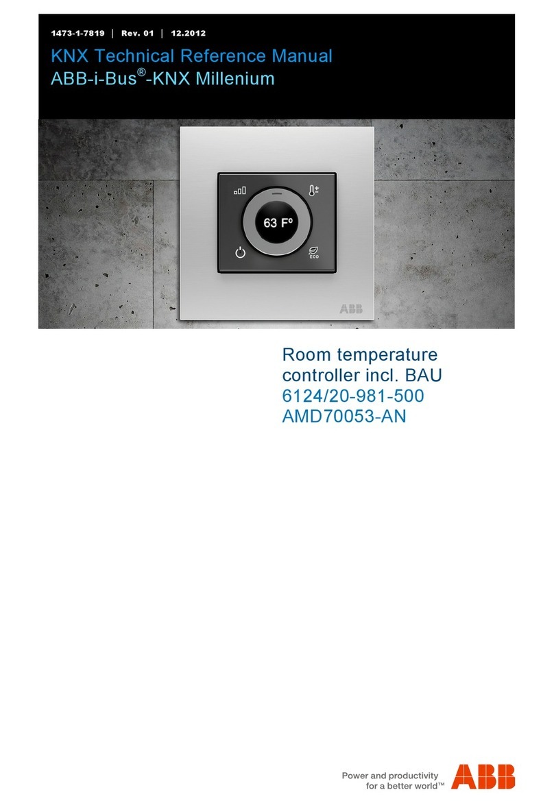
ABB Caldion FCR-F-2-4.2.21.1 Series User manual

Product manual │16.12.2021
ABB-free@home®
FCR‐F‐2‐4.2.21.1‐xx
Caldion®RoomTemperaturecontroller
FCR‐F‐2‐4.6.21.1‐xx
Caldion®RoomTemperaturecontroller
Branding -- Release 2018-01- 01

Table of contents
Product manual 2CKA001373B8563
│
2
Table of cont ents
1
Information on the manual ............................................................................................................................. 4
2
Safety ............................................................................................................................................................. 5
2.1
Information and symbols used ........................................................................................................... 5
2.2
Intended use ...................................................................................................................................... 6
2.3
Improper use ...................................................................................................................................... 6
2.4
Target group / Qualifications of personnel ......................................................................................... 6
2.5
Safety instructions .............................................................................................................................. 7
2.6
Environment ....................................................................................................................................... 8
3
Setup and function ......................................................................................................................................... 9
3.1
Scope of supply .................................................................................................................................. 9
3.2
Overview of types ............................................................................................................................. 10
3.3
Functions .......................................................................................................................................... 11
3.4
Device overview ............................................................................................................................... 13
4
Technical data ............................................................................................................................................. 14
4.1
Dimensional drawings ...................................................................................................................... 15
5
Connection and installation ......................................................................................................................... 16
5.1
Planning instructions ........................................................................................................................ 16
5.2
Safety instructions ............................................................................................................................ 16
5.3
Installation site ................................................................................................................................. 17
5.4
Mounting ........................................................................................................................................... 18
5.5
Electrical connection ........................................................................................................................ 20
6
Commissioning ............................................................................................................................................ 25
6.1
Allocation of devices and definition of channels .............................................................................. 25
6.1.1
Add device ................................................................................................................................. 26
6.2
Setting options per channel ............................................................................................................. 29
6.2.1
Parameter settings of room temperature controller .................................................................... 30
6.2.2
Open overview of devices .......................................................................................................... 33
6.2.2.1
Parameter settings of fan coil actuator ........................................................ 35
6.2.2.2
Other settings .............................................................................................. 37
6.3
Control and measuring precision ..................................................................................................... 39
7
Update ......................................................................................................................................................... 40
8
Operation ..................................................................................................................................................... 41
8.1
Control elements .............................................................................................................................. 41
8.2
Operating modes .............................................................................................................................. 4 3
8.2.1
Changing the operating status (heating/cooling) ........................................................................ 45
8.3
Displays / messages ........................................................................................................................ 46
9
Maintenance ................................................................................................................................................ 47
9.1
Cleaning ........................................................................................................................................... 47

Table of contents
Product manual 2CKA001373B8563
│
3
10
Notes ............................................................................................................................................................ 48
11
Index ............................................................................................................................................................ 49

Information on the manual
Product manual 2CKA001373B8563
│
4
1 Information on the manual
Please read this manual carefully and observe the information it contains. This will assist you in
preventing injuries and damage to property, and ensure both reliable operation and a long
service life for the device.
Please keep this manual in a safe place.
If you pass the device on, also pass on this manual along with it.
ABB accepts no liability for any failure to observe the instructions in this manual.
If you require additional information or have questions about the device, please contact ABB or
visit our Internet site at:
https://abb.com/freeathome

Safety
Product manual 2CKA001373B8563
│
5
2 Safety
The device has been constructed according to the latest valid regulations governing technology
and is operationally reliable. It has been tested and left the factory in a technically safe and
reliable state.
However, residual hazards remain. Read and adhere to the safety instructions to prevent
hazards of this kind.
ABB accepts no liability for any failure to observe the safety instructions.
2.1 Information and symbols used
The following Instructions point to particular hazards involved in the use of the device or provide
practical instructions:
Danger
Risk of death / serious damage to health
– The respective warning symbol in connection with the signal word "Danger"
indicates an imminently threatening danger which leads to death or serious
(irreversible) injuries.
Warning
Serious damage to health
– The respective warning symbol in connection with the signal word "Warning"
indicates a threatening danger which can lead to death or serious
(irreversible) injuries.
Caution
Damage to health
– The respective warning symbol in connection with the signal word "Caution"
indicates a danger which can lead to minor (reversible) injuries.
Attention
Damage to property
– This symbol in connection with the signal word "Attention" indicates a
situation which could cause damage to the product itself or to objects in its
surroundings.
NOTE
This symbol in connection with the word "Note" indicates useful tips and
recommendations for the efficient handling of the product.
This symbol alerts to electric voltage.

Safety
Product manual 2CKA001373B8563
│
6
2.2 Intended use
This device is a room temperature controller for decentralized flush-mounted installation. For
controlling fan coil units or blower convectors.
The device is intended for the following:
■ Operation according to the listed technical data
■ Installation in dry interior rooms and suitable flush-mounted boxes
■ Use with the connecting options available on the device
The intended use also includes adherence to all specifications in this manual.
2.3 Improper use
Each use not listed in Chapter 2.2 “Intended use“ on page 6 is deemed improper use and can
lead to personal injury and damage to property.
ABB is not liable for damages caused by use deemed contrary to the intended use of the
device. The associated risk is borne exclusively by the user/operator.
The device is not intended for the following:
■ Unauthorized structural changes
■ Repairs
■ Outdoor use
■ The use in bathroom areas
■ Insert with an additional bus coupler
2.4 Target group / Qualifications of personnel
Installation, commissioning and maintenance of the device must only be carried out by trained
and properly qualified electrical installers.
The electrical installer must have read and understood the manual and follow the instructions
provided.
The electrical installer must adhere to the valid national regulations in his/her country governing
the installation, functional test, repair and maintenance of electrical products.
The electrical installer must be familiar with and correctly apply the "five safety rules" (DIN VDE
0105, EN 50110):
1. Disconnect
2. Secure against being re-connected
3. Ensure there is no voltage
4. Connect to earth and short-circuit
5. Cover or barricade adjacent live parts

Safety
Product manual 2CKA001373B8563
│
7
2.5 Safety instructions
Danger - Electric voltage!
Electric voltage! Risk of death and fire due to electric voltage of 100 … 240 V.
Dangerous currents flow through the body when coming into direct or indirect
contact with live components. This can result in electric shock, burns or even
death.
■ Work on the 100 … 240 V supply system may only be performed by
authorised and qualified electricians.
■ Disconnect the mains power supply before installation or dismantling.
■ Never use the device with damaged connecting cables.
■ Do not open covers firmly bolted to the housing of the device.
■ Use the device only in a technically faultless state.
■ Do not make changes to or perform repairs on the device, on its components
or its accessories.
Caution! - Risk of damaging the device due to external factors!
Moisture and contamination can damage the device.
■ Protect the device against humidity, dirt and damage during transport,
storage and operation.

Safety
Product manual 2CKA001373B8563
│
8
2.6 Environment
Consider the protection of the environment!
Used electric and electronic devices must not be disposed of with domestic
waste.
– The device contains valuable raw materials which can be recycled.
Therefore, dispose of the device at the appropriate collecting depot.
All packaging materials and devices bear the markings and test seals for proper disposal.
Always dispose of the packaging material and electric devices and their components via the
authorized collecting depots and disposal companies.
The products meet the legal requirements, in particular the laws governing electronic and
electrical devices and the REACH ordinance.
(EU Directive 2012/19/EU WEEE and 2011/65/EU RoHS)
(EU REACH ordinance and law for the implementation of the ordinance (EC) No.1907/2006).

Setup and function
Product manual 2CKA001373B8563
│
9
3 Setup and function
1
3
2
Fig. 1: Product overview
[1] Flush-mounted insert
[2] Anti-theft devices (clip)
[3] Front cover with indication and control elements
This device is a room temperature controller for decentralized flush-mounted installation.
The room temperature controller with bus coupler is suitable for the control of fan coil units
(blower convectors).
The unit serves as a control element and also forms a sensor/actuator unit within the
free@home system. The integrated bus coupler makes the connection to the free@home bus
line possible.
The devices are pre-programmed. The devices must be parameterised for the use of the
functions.
3.1 Scope of supply
The scope of supply only contains the flush-mounted insert [1] the clip for the anti-theft device
[2] and the front cover [3].
Two screws each (M3.5 x 35 and M4 x 35) for fixing in the flush-mounted box are included. The
required flush-mounted box must comply with British standards and be at least 40 mm deep.
The flush-mounted box is not included in the scope of delivery.

Setup and function
Product manual 2CKA001373B8563
│
10
3.2 Overview of types
Article no. Colour Connection variant
FCR-F-2-4.2.21.1-84 White 2/4-pipe, 0-10 V
FCR-F-2-4.2.21.1-81 black 2/4-pipe, 0-10 V
FCR-F-2-4.6.21.1-84 White 2/4-pipe, On/Off
FCR-F-2-4.6.21.1-81 black 2/4-pipe, On/Off
Table 1: Overview of types Caldion® Room Temperature controller
Article no. Output
channels
Switching load
(Total load to
terminal L (Fx +
Vxx))
FCR-F-2-4.2.21.1-xx
2-pipe 1
7 A
FCR-F-2-4.2.21.1-xx
2-pipe with additional
heater
2
7 A
FCR-F-2-4.2.21.1-xx
4-pipe 2
7 A
FCR-F-2-4.6.21.1-xx
2-pipe 1
7 A
FCR-F-2-4.6.21.1-xx
2-pipe with additional
heater
2
7 A
FCR-F-2-4.6.21.1-xx
4-pipe 2
7 A

Setup and function
Product manual 2CKA001373B8563
│
11
3.3 Functions
der
The Caldion® room temperature controller controls blower convectors (also referred to as fan
coil units).
Blower convectors are used for decentralised heating or cooling of individual rooms and are
supplied by central heating and cooling systems. There are two different systems:
■ 2-pipe systems carry cold or hot water in the supply and return lines.
■ 4-pipe systems carry cold and hot water simultaneously in two separate circuits.
When connected to a 2-pipe system, the Caldion® room temperature controller can be used
either for heating only or for cooling only. When connected to a 4-pipe system, the
heating/cooling operating mode can be changed.
For the supply of heat or cold, the water circuits are controlled via valves. Depending on the fan
coil unit used, the valves are controlled via an On/Off signal or in an analogue manner via a
0...10 V signal.
The heat or cold is released to the room air at three different speeds via a fan (ventilator)
integrated into the blower convector. As a result, the room temperature can be adjusted quickly.
Caldion® room temperature controller control fans either as a single-phase fan with up to three
fan speeds via step or changeover actuation. For speed-controlled fans in changeover
operation mode, to ensure that no two fan speeds can be switched on simultaneously. An
additional programmable switch-over delay is provided for this purpose. Three-phase drives are
not supported.
The room temperature is measured by the internal temperature sensor.
Basic functions
■ Switch-on/switch-off.
■ Set the operation mode (heating, cooling).
■ Set the temperature (correction of the automatic temperature control).
■ Set the temperature setpoint.
■ Set the fan speed.
■ Set ECO mode (economy mode) (temperature regulation in energy-saving mode).
Optional functions
Other devices can be connected to the physical input of the Caldion® room temperature
controller.
By connecting the following sensors, temperature regulation or the change of operation modes
can be controlled:
■ Window contact - sensor
■ External temperature sensor
– The value measured by the external temperature sensor can be used as a limit value for
temperature regulation or to calculate an average value.
■ Fill level sensor of a collecting tray
■ Dew point sensor
When using a 2-pipe system, an additional heater (e.g., an electric heater) can be connected as
an option.

Setup and function
Product manual 2CKA001373B8563
│
12
The following table provides an overview of the possible functions and applications of the
device:
Icon of the user
interface Information
Name: Room temperature controller
Type: Sensor
Made available by: Room temperature controller
Job type: Regulates ABB-free@home
®
fan coil
actuators
Table 2: Overview of functions

Setup and function
Product manual 2CKA001373B8563
│
13
3.4 Device overview
1
Fig. 2: Room temperature controller, front view
[1] Display with indication and control elements
1
2
Fig. 3: Room temperature controller, rear view
[1] Top connection strip
[2] Bottom connection strip
12
Fig. 4: Room temperature controller, bottom view
[1] Temperature sensor
[2] Programming button

Technical data
Product manual 2CKA001373B8563
│
14
4 Technical data
Designation Value
Power supply 110 V…230 V AC ±10%
50 / 60 Hz
Power consumption ≤ 3 VA
Maximum allowable input load at L
Fan + valve + optional electric heater ≤ 7 A
Wiring
Wiring cross section on
L, N, F1, F2, F3, VA, VB 1 x 0.5…2.5 mm2
Wiring cross section at
COM, E1, E2, 0...10 VA,
0...10 VB and F@H
connection
Stranded wire
1 x 0.5…1.5 mm2
Bus connection
Wiring terminal 0.4 - 0.8 mm
Nominal voltage 30 V DC
SELV range: 21…32 V DC
Outputs
Control output at F1, F2,
F3-N, VA/VB-N ; RO-N
230 V AC
>8.3 mA / <5(2) A
[Resistive (Inductive)]
Total load current
through terminal L (Fx +
Vxx) ≤ 7 A
Total load of control
output
0~10 VA-COM´/
0~10 VB-COM
SELV range: 0…10 V DC
<1.5 mA / >10 kohms
Inputs E1 and E2
Physical inputs E1 and
E2 10 V / 1 mA
E1 Standard window contact
E2 NTC 10-01: 10K
(B-Constant=3936~3976)
Cable length at input < 30 m
Degree of protection IP20
Protection class II EN 60730-1
Isolation category Overvoltage category III
EN 60 664-1
Ambient temperature -5 °C to +50 °C
Storage temperature -25 °C to +70 °C
Table 3: Technical data

Technical data
Product manual 2CKA001373B8563
│
15
4.1 Dimensional drawings
Notice
All dimensions are specified in mm. All device types described in this manual
have the same dimensions.
Fig. 5: Dimensions of all described device types (all dimensions in mm)
86
86
52
16 34,2

Connection and installation
Product manual 2CKA001373B8563
│
16
5 Connection and installation
5.1 Planning instructions
Note
Planning and application instructions for the system are available in system
manual for ABB-free@home®. This can be downloaded via
www.abb.com/freeathome.
5.2 Safety instructions
Danger - Electric shock due to short-circuit!
Risk of death due to electrical voltage of 100 to 240 V during short-circuit in the
low-voltage line.
– Low-voltage and 100 - 240 V lines must not be installed together in a flush-
mounted box!
– Observe the spatial division during installation (> 10 mm) of SELV electric
circuits to other electric circuits.
– If the minimum distance is insufficient, use electronic boxes and insulating
tubes.
– Observe the correct polarity.
– Observe the relevant standards.
Danger - Electric voltage!
Install the device only if you have the necessary electrical engineering
knowledge and experience.
■ Incorrect installation endangers your life and that of the users of the
electrical system.
■ Incorrect installation can cause serious damage to property, e.g. due to fire.
The minimum necessary expert knowledge and requirements for the installation
are as follows:
■ Apply the "five safety rules" (DIN VDE 0105, EN 50110):
1. Disconnect
2. Secure against being re-connected
3. Ensure there is no voltage
4. Connect to earth and short-circuit
5. Cover or barricade adjacent live parts.
■ Use suitable personal protective clothing.
■ Use only suitable tools and measuring devices.
■ Check the type of supply network (TN system, IT system, TT system) to
secure the following power supply conditions (classic connection to ground,
protective earthing, necessary additional measures, etc.).
■ Observe the correct polarity.

Connection and installation
Product manual 2CKA001373B8563
│
17
5.3 Installation site
When selecting the installation location, ensure that there is a distance to sources of heat or
cold.
Heat or cold sources influence the function of the internal temperature sensor.
Fig. 6: Installation sites
The device should be mounted on a wall opposite the heat source. The distance to side walls or
door frames should be at least 50 cm. The distance to the floor should be about 150 cm.
■ Do not mount the device on the wall. Low outside temperatures have an effect on
temperature regulation.
■ The room temperature controller must not come into direct contact with liquids.
■ Do not mount the device in direct sunlight, near radiators, windows, light sources or behind
curtains.

Connection and installation
Product manual 2CKA001373B8563
│
18
5.4 Mounting
Once you have connected all cables for the electrical connection and the connection to the
busline, mount the device in the flush-mounted box.
To install the device, perform the following steps:
1
2
Fig. 7: Installation position of flush-mounted insert
[1] Insert the flush-mounted insert into the flush-mounted box.
– Pay attention to the correct installation position.
– Orientate yourself on the " TOP" marking.
[2] Screw the flush-mounted insert in place.
– Use the provided screws.
Fig. 8: Fitting the front cover
[3] Place the front cover on the lower edge of the flush-mounted insert.
[4] Push the anti-theft device (clip) about halfway into the provided shaft.
– Pay attention to the correct orientation of the clip.
– When the clip is pushed in about halfway, the front cover can snap into place.
3
4
5

Connection and installation
Product manual 2CKA001373B8563
│
19
[5] Press the front cover closed.
6
Fig. 9: Securing the device
[6] Once the front cover is closed, slide the clip all the way down to secure the device.

Connection and installation
Product manual 2CKA001373B8563
│
20
5.5 Electrical connection
The electrical connection and the connection to the free@home bus are made via screw
terminals. The description of the terminals is found on the housing.
The installation depends on the existing fan coil unit.
Connection of the F@H busline
Fig. 10: Connection of the F@H busline
Notice
Observe the correct polarity when connecting the ABB-free@home® busline!
Cable connection of the physical inputs E1 and COM
Notice
The physical input E1 is intended for the connection of a window contact. If no
window contact is connected, the physical inputs E1 and COM must be
connected with a cable (closed contact).
On delivery, the connections E1 and COM are connected with a cable. Without a cable
connection, the device operates in frost/heat protection mode.
Cconnection of two pipes with an electrical heater
Notice
When connecting a two-pipe blower convector, the free switching actuator of
cable duct VB/RO can be used to connect another heater (e.g., for an electric
heater).
In order not to exceed the maximum output load of the output channel, the connection of an
electric heater must be combined with an external relay.
This manual suits for next models
5
Table of contents
Other ABB Temperature Controllers manuals

ABB
ABB -i-Bus-KNX Millenium Product manual

ABB
ABB i-bus KNX Yucus YUB/U1.0.1 Series Product manual

ABB
ABB SCC-C I-Tron Use and care manual

ABB
ABB 1795 500 Series User manual

ABB
ABB TSP341-N Operating and maintenance manual

ABB
ABB CM 16 User manual

ABB
ABB TTF300 User manual

ABB
ABB 6134-24-102-500 User manual

ABB
ABB TSHD User manual

ABB
ABB i-bus 6108/18-BS-500 Product manual