manuals.online logo
Brands
  1. Home
  2. •
  3. Brands
  4. •
  5. alre
  6. •
  7. Temperature Controllers
  8. •
  9. alre FETR 101.715 Guide

alre FETR 101.715 Guide

FETR 101.715
Stand 3.2020 (20/024) 5 21 127 10
Elektronischer Unterputz-Fußbodentemperaturregler im Flächenschalterrahmen
Flush framed electronic floor temperature controller
No persons other than expert electricians only must open this device in due compliance with the
wiring diagram shown in the housing cover / on the housing / represented in the corresponding
operating instructions. All expert electricians committed to the execution of any such works must
comply with the relevant safety regulations currently operative and in force.
Caution! The operation of the controller in the vicinity of other devices that do not comply wi-
th the EMC directives may affect its functions. The company charged with the installation of
the device must, after the completion of the installation works, instruct the user of the control
system into its functions and in how to operate it correctly. These operating instructions must
be kept at a place that can be accessed freely by the operating and/or servicing personnel in
charge.
Sicherheitshinweis!
DSafety information! GB
Dieses Gerät darf nur durch eine Elektrofachkraft geöffnet und gemäß dem entsprechenden
Schaltbild im Gehäusedeckel / auf dem Gehäuse / in der Bedienungsanleitung installiert wer-
den. Dabei sind die bestehenden Sicherheitsvorschriften zu beachten.
Achtung! Der Betrieb in der Nähe von Geräten, welche nicht den EMV-Richtlinien entsprechen,
kann zur Beeinflussung der Gerätefunktionen führen. Nach der Installation ist der Betreiber,
durch die ausführende Installationsfirma, in die Funktion und Bedienung der Regelung einzu-
weisen. Die Bedienungsanleitung muss für Bedien- und Wartungspersonal an frei zugänglicher
Stelle aufbewahrt werden.
1. Anwendung 1. Application
This electronic two-point controller has been specially devised for the control of electric or
warm-water heating systems, additional floor heating systems and other surface temperature
equalization systems. Regarding other applications not to be foreseen by the manufacturer of
this device, the safety standards concerning these applications need to be followed and ad-
hered to. Regarding the aptitude of the device for any such other application, please refer to
section 10. herein (Warranty).
Dieser elektronische Zweipunktregler wurde speziell zur Regelung elektrischer oder Warmwas-
ser-Heizungen/Zusatzheizungen für Fußböden und anderer Oberflächentemperiersysteme ent-
wickelt. Für andere vom Hersteller nicht vorherzusehende Einsatzgebiete sind die dort gültigen
Sicherheitsvorschriften zu beachten. Eignung hierfür siehe Punkt 10. Gewährleistung.
3. Montage und Installation 3. Mounting and installation
2. Funktion
Der Regler misst mit einem in den Fußboden eingebrachten Fühler die Temperatur und regelt
diese mit einer Schaltdifferenz von ca.1K auf den eingestellten Sollwert. Aus dieser Regelung
ergibt sich eine Oberflächentemperatur, die hauptsächlich durch den Aufbau des Fußbodens
bestimmt wird. Bei elektrischen Heizungen ist darauf zu achten, dass diese auch bei Dauerbe-
trieb den Oberflächenaufbau nicht überhitzen können.
Achtung! Bei Oberflächen, ausgeführt als Sitzmöbel oder Stellfläche, ist darauf zu achten, dass
die eingestellte Temperatur nicht zu einer Gesundheitsgefährdung von Personen oder Entflam-
mung von Gegenständen führen kann. Zur Vermeidung einer zu hohen Temperatureinstellung,
kann der Einstellbereich mechanisch unter dem Einstellknopf eingeschränkt werden (vgl. Punkt
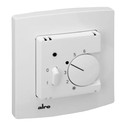
3.1). Der FETR 101.715 verfügt über einen EIN/AUS-Schalter mit dem die Regelung außer Be-
trieb genommen werden kann. Die rote Lampe zeigt die aktive Heizung an. Bei Fühlerbruch,
Fühlerkurzschluss oder einer Fühlertemperatur unter -15°C (entspricht Fühlerbruch) wird die
Heizung ausgeschaltet. Wird an der Klemme die Phase geschaltet, senkt der Regler den
eingestellten Sollwert um ca.5K ab. Die grüne Lampe zeigt diesen Energiesparmodus an.
Je nach Gerätetyp oder Verpackungsgröße, wird das Gerät entweder geschlossen oder der
schnelleren Montage wegen geöffnet ausgeliefert. Das Gerät mit dem 50 x 50 mm Gehäuse-
deckel ist mittels Zwischenrahmen der Schalterhersteller nach DIN 49075 in nahezu alle Schal-
terprogramme integrierbar. Das Gerät mit dem 55 x 55 mm Gehäusedeckel ist ebenfalls für
diverse Schalterprogramme geeignet. Bei Mehrfachrahmen ist der Regler immer an unterster
Stelle zu montieren. Für die Befestigungsschraube ist je nach verwendeter Schraube ein PZ
1 bzw. T7 Schraubendreher zu verwenden. Zum Öffnen des
Reglers ist die Schraube nach Ab-
ziehen des Einstellknopfes zu lösen und die Reglerkappe
inklusive Rahmen abzunehmen. Nach
elektrischem Anschluss und Montage in die UP-Dose, ist der Regler in umgekehrter Reihenfol-
ge wieder zu schließen.
Fühlerleitungen müssen aus Sicherheitsgründen und um einen Austausch eines defekten Füh-
lers zu gewährleisten im Schutzrohr verbaut werden. Der mitgelieferte Fühler verfügt über eine
H03VV-Leitung. Die nach EN 60730-1 vorgeschriebene doppelte Isolierung ist bei einer Fühler-
verlängerung mit H03VV-, oder H05VV-Leitungen, auch an den Verbindungsstellen einzuhalten.
Es ist darauf zu achten, dass die Fühlerleitung nicht parallel zu netzspannungsführenden Lei-
tungen verlegt wird. Ist die Parallelverlegung nicht zu vermeiden, muss eine geschirmte Leitung
verwendet und der Schirm auf die Fühlermasse gelegt werden. Zum Verschließen des Schutz-
rohres im Estrich wird die Schutzhülse THF verwendet (vgl. Punkt 6. Zubehör). Um eine optima-
le Wärmeverteilung im Fußboden zu erreichen, muss der Fühler mittig zwischen zwei Heizlei-
tern positioniert werden. Bei Warmwasser-Beheizten Oberflächen sind stromlos geschlossene
Ventile zu verwenden.
Gegebenenfalls benötigte Temperaturbegrenzungen müssen zusätzlich installiert werden
3.1. Begrenzung des Einstellbereichs
Um den Einstellbereich Einzuengen, wird der sich unter dem Einstellknopf befindliche Stift ab-
gezogen und die Einstellfahnen verstellt (rot für maximal und blau für minimal mögliche Ein-
stellung). Anschließend wird der Stift wieder eingesteckt und somit die Begrenzungen arretiert.
Pin for the setting of
the max.
temperature value
Pin for the setting of
the min.
temperature value
Einstellfahne für
maximalen
Temperaturwert
Einstellfahne für
minimalen
Temperaturwert
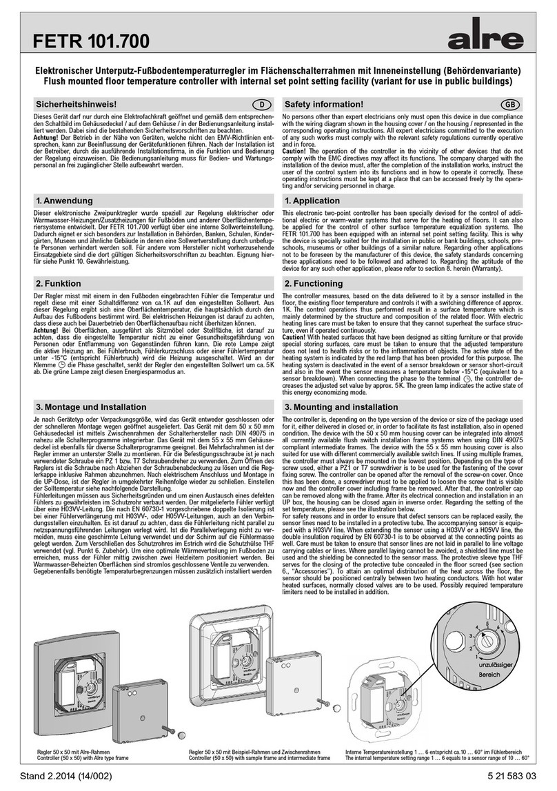
Regler 50 x 50 mit Alre-Rahmen
Controller (50 x 50) with Alre type frame Regler 50 x 50 mit Beispiel-Rahmen und Zwischenrahmen
Controller (50 x 50) with sample frame and intermediate frame Regler 55 x 55 mit Beispiel-Rahmen
Controller (55 x 55) with sample frame
2. Functioning
The controller measures, based on the data delivered to it by a sensor installed in the floor, the
existing floor temperature and controls it with a switching difference of approx. 1K. The control
operations thus performed result in a surface temperature which is mainly determined by the
structure and composition of the related floor. With electric heating lines care must be taken to
ensure that they cannot superheat the surface structure, even if operated continuously.
Caution! With heated surfaces that have been designed as sitting furniture or that provide
special
storing surfaces, care must be taken to ensure that the adjusted temperature does not lead to
health risks or to the inflammation of objects. The setting range of the device can, in order to
prevent from the setting of temperatures that are too high, be restricted mechanically by means
of a special facility that exists underneath of the adjusting knob (see section 3.1). The FETR
101.715 is equipped with an ON/OFF switch that enables to activate or deactivate its control
operations. The active state of the heating system is indicated by the red lamp that has been
provided for this purpose. The heating system is deactivated in the event of a sensor break-
down or sensor short-circuit and also in the event the sensor measures a temperature below
-15°C (equivalent to a sensor breakdown). When connecting the phase to the terminal , the
controller decreases the adjusted set value by approx. 5K. The green lamp indicates the active
state of this energy economizing mode.
The controller is, depending on the type version of the device or size of the package used for
it, either delivered in closed or, in order to facilitate its fast installation, also in opened conditi-
on. The device with the 50 x 50 mm housing cover can be integrated into almost all currently
available flush switch installation frame systems when using DIN 49075 compliant intermediate
frames. The device with the 55 x 55 mm housing cover is also suited for use with different com-
mercially available switch lines. If using multiple frames, the controller must always be mounted
in the lowest position. Depending on the type of screw used, either a PZ1 or T7 screwdriver is
to be used for the fastening of the cover fixing screw. The controller can be opened after the
removal of the adjusting knob. Once this has been done, a screwdriver must to be applied to
loosen the screw that is visible now. After that, the controller cap can be removed along with the
frame. After its electrical connection and installation in an UP box, the housing can be closed
again in inverse
order. For safety reasons and in order to ensure that defect sensors can be
replaced easily,
the sensor lines need to be installed in a protective tube. The accompanying
sensor is equipped with a H03VV line. When extending the sensor using a H03VV or a H05VV
line, the double insulation required by EN 60730-1 is to be observed at the connecting points as
well. Care must be taken to ensure that sensor lines are not laid in parallel to line voltage car-
rying cables or lines. Where parallel laying cannot be avoided, a shielded line must be used and
the shielding be connected to the sensor mass. The protective sleeve type THF serves for the
closing of the protective tube concealed in the floor screed (see section 6., “Accessories”). To
attain an optimal distribution of the heat across the floor, the sensor should be positioned cen-
trally between two heating conductors. With hot water heated surfaces, normally closed valves
are to be used. Possibly required temperature limiters need to be installed in addition.
3.1. Limitation of the setting range
The setting range can be limited by removing the pin that exists underneath of the adjusting
knob and by adjusting the setting pins as needed (red pin for maximum and blue pin for mini-
mum possible setting). After that, the pin needs to be plugged in again in order to fix the limits.
Rot = Regler fordert Wärme an
Grün = Energiesparberieb (Nachtabsenkung)
4. Anzeigen
5. Technische Daten 5. Technical data
6. Zubehör 6. Accessories
Betriebsspannung: 230V~ / 50Hz
Regelbereich: 10 … 50ºC
Schaltdifferenz: ca.1K
Leistungsaufnahme: ca.1VA
Temperaturabsenkung: ca.5K fest (Anschluss L1 an )
Kontakt: Schließer 230V~ max.16(2)A
Externer Fühler: 2kΩNTC entspr. DIN 44574
(doppelt isoliert) entspr. DIN EN 60730-2-1
Fühlerbrucherkennung: Heizung wird abgeschaltet
Anzeigen: LED für Heizen rot, für Nachtabsenkung grün
Schraubklemmen: 0,5 – 2,5 mm2
Befestigung: in UP-Dose Ø 55 mm
Wirkungsweise: Typ 1.C
Verschmutzungsgrad: 2
Bemessungsstoßspannung: 4000V
Schutzart: IP30
Schutzklasse: Nach sachgemäßer Montage werden die Anforderungen
der Schutzklasse II erfüllt.
Umgebungstemperatur: 0 … 40ºC
Lagertemperatur: -20 … +70ºC
Temperatur der Kugeldruckprüfung: 75°C
Operating range: 230V~ / 50Hz
Control range: 10 … 50ºC
Switching difference: approx.1K
Power consumption: approx.1VA
Temperature decrease: approx. 5K (fixed); (connection of L1 to )
Contact: make contact, max. 230V~, max.16(2)A
External sensor (double-insulated): 2kΩ, NTC acc. to. DIN 44574
in compliance with DIN EN 60730-2-1
Sensor breakdown detection: heating is turned off
Indicators: red LED for “heating” and green LED
for “night decrease mode”
Terminal screws: screw terminals (0.5 … 2.5 mm2)
Mounting: in an UP box (Ø 55 mm)
Mode de fonctionnement: type 1.C
Degré de pollution: 2
Tension nominale d’impulsion: 4000V
Degree of protection: IP30
Protection class: The requirements of the protection class II will be
met after correct installation.
Ambient temperature: 0 … 40ºC
Storage temperature: -20 … +70ºC
Temperature of ball indentation test: 75°C
– Ersatzfühler HF-8/4-K2
– THF – Schutzhülse bei Estrichmontage des Fühlers, passend für Leerrohr Ø 20 mm – Spare sensor HF-8/4-K2
– Protecting sleeve, type THF, for the installation of the sensor into the pavement
(inside a suitable empty conduit, Ø 20 mm)
Red = controller requests heat supply
Green = energy economizing mode (night temperature decrease mode)
4. Indicators
8. Fühlerkennwerte / Sensor characteristics 9. Verwendete Symbole / Explanation of symbols
7. Maßzeichnungen und Anschluss-Schaltbilder / Dimensioned drawings and connection diagrams
Die angegebenen technischen Daten wurden durch uns jeweils in einem dafür geeigneten Prüf- und Testumfeld (hierzu geben wir auf Anfrage Auskunft) ermittelt und stellen nur auf dieser Grundlage
die vereinbarte Beschaffenheit dar. Die Prüfung der Eignung für den vom Auftraggeber / Kunden vorgesehenen Verwendungszweck oder den Einsatz unter den konkreten Gebrauchsbedingungen ob-
liegt dem Auftraggeber / Kunden; hierfür übernehmen wir keine Gewährleistung. Änderungen vorbehalten.
We determined the technical data provided in an inspection and test environment suited to this task (we are happy to provide details on request) and this data only presents the agreed properties on
this basis. The purchaser / customer is responsible for checking the suitability of the use or usage intended by the purchaser / customer under the specific conditions of use; we do not accept any liabili-
ty for this. We reserve the right to amendments.
ALRE-IT Regeltechnik GmbH · Richard-Tauber-Damm 10 · D-12277 Berlin
Tel.: +49(0)30/399 84-0 · Fax: +49(0)30/39170 05 · [email protected] · www.alre.de
10. Gewährleistung / Warranty
Table of sensor characteristics NTC 2k
Sensor Resistance
temperature [°C] value [kΩ]
0 5.642
10 3.657
15 2.973
20 2.431
25 2.000
30 1.654
40 1.151
50 0.816
60 0.590
Fühlerwerttabelle NTC 2k
Fühler- Wider-
temperatur [°C] standswert [kΩ]
0 5,642
10 3,657
15 2,973
20 2,431
25 2,000
30 1,654
40 1,151
50 0,816
60 0,590
Regler 50 x 50 mit Alre-Rahmen
Controller (50 x 50) with Alre type frame Regler 50 x 50 mit Beispiel-Rahmen und Zwischenrahmen
Controller (50 x 50) with sample frame and intermediate frame Regler 55 x 55 mit Beispiel-Rahmen
Controller (55 x 55) with sample frame
Bedien- und Anzeigesymbole
Regelung EIN
Regelung AUS
Heizung EIN
Nachtabsenkung EIN
Anschluss Heizung
Anschluss Temperaturabsenkung
Anschluss Phase L
Anschluss Neutralleiter N
Anschluss Fühler F
Operating and display symbols
Control ON
Control OFF
Heating ON
Night decrease ON
Heating connection
Connection Temperature decrease
Phase connection L
Neutral conductor connection N
Sensor connection F
Regolatore elettronico da incasso della temperatura del pavimento nel telaio dell‘interruttore di superficie
Elektronický regulátor podlahového topení do krabice pod omítku v
Linguetta di regolazione
per la regolazione del
valore
massimo di temperatura
Linguetta di regolazione
per la regolazione del
valore
Regolatore 50 x 50 con telaio Alre
Regulátor 50 x 50 s rámem Alre Regolatore 50 x 50 con telaio campione e telaio intermedio
Regulátor 50 x 50 s příkladným rámem a mezirámem Regolatore 55 x 55 con telaio campione
Regulátor 55 x 55 s příkladným rámem
Informazioni per la sicurezza! I
Questo apparecchio può essere aperto solo da un elettricista qualificato e installato secondo
lo schema elettrico corrispondente nel coperchio dell'alloggiamento / sull'alloggiamento / nelle
istruzioni d'uso. Devono essere rispettate le norme di sicurezza presenti.
Attenzione! Il funzionamento in prossimità di apparecchi non conformi alle direttive EMC può
influire sulle funzioni dell'apparecchio. Dopo l'installazione, il gestore deve essere istruito dalla
società di installazione sul funzionamento e sull'esercizio del sistema di regolazione Le istruzio-
ni per l'uso devono essere conservate in un luogo liberamente accessibile al personale addetto
all'uso e alla manutenzione.
1. Applicazione
Questo regolatore elettronico a due posizioni è stato sviluppato appositamente per controllare i
sistemi di riscaldamento elettrico o ad acqua calda/riscaldamento supplementare per pavimenti
e altri sistemi di controllo della temperatura di superficie. Per altri campi di applicazione non
prevedibili dal produttore, devono essere rispettate le disposizioni di sicurezza ivi applicabili.
Per l'idoneità vedere il punto 10. Garanzia.
3. Montaggio e installazione
2. Funzione
Il regolatore misura la temperatura con un sensore installato nel pavimento e la regola con un
differenziale di commutazione di ca. 1K rispetto al valore nominale. Questo controllo determina
una temperatura superficiale che è determinata principalmente dalla struttura del pavimento.
Nel caso di riscaldamenti elettrici, occorre fare attenzione che non possano surriscaldare la
struttura superficiale anche durante il funzionamento continuo.
Attenzione! Per le superfici, concepite come mobili da seduta o come spazio per il pavimento,
occorre fare attenzione che la temperatura impostata non possa comportare un pericolo per la
salute delle persone o un'infiammazione degli oggetti. Per evitare un'impostazione di tempera-
tura troppo elevata, il campo di regolazione può essere limitato meccanicamente sotto la ma-
nopola di regolazione ( cfr. punto 3.1). Il FETR 101.715 è dotato di un interruttore ON/OFF con
il quale il sistema di controllo può essere messo fuori servizio. La spia rossa indica il riscalda-
mento attivo. In caso di rottura del sensore, cortocircuito del sensore o temperatura del sensore
inferiore a -15°C (corrisponde alla rottura del sensore) il riscaldamento viene spento. Se la fase
viene commutata sul morsetto , il regolatore abbassa il valore nominale impostato di circa
5K. La spia verde indica questa modalità di risparmio energetico.
A seconda del tipo di apparecchio o delle dimensioni dell'imballaggio, l'apparecchio viene
fornito chiuso o aperto per una più rapida installazione. L'apparecchio con il coperchio
dell'alloggiamento di 50 x 50 mm può essere integrato in quasi tutti i programmi di commu-
tazione mediante telai intermedi dei produttori di interruttori secondo la norma DIN 49075.
L'apparecchio con il coperchio dell'alloggiamento di 55 x 55 mm è adatto anche per diversi pro-
grammi di commutazione. Nel caso di telai multipli, il regolatore deve essere sempre montato
nella posizione più bassa. A seconda della vite utilizzata, per la vite di fissaggio deve essere
utilizzato un cacciavite PZ 1 o T7.
Per aprire il regolatore, allentare la vite dopo aver tolto la
manopola di regolazione e rimosso il coperchio del regolatore, compreso il telaio.
Dopo il col-
legamento elettrico e il montaggio nella scatola da incasso, il regolatore deve essere richiuso
in ordine inverso.
Le linee del sensore devono essere installate nel tubo di protezione per motivi di sicurezza e
per garantire che un sensore difettoso possa essere sostituito. Il sensore in dotazione ha una
linea H03VV. Per un'estensione del sensore con linee H03VVV o H05VV, anche nei punti di
collegamento, è necessario rispettare il doppio isolamento prescritto dalla norma EN 60730-
1. È necessario assicurarsi che la linea del sensore non sia posata in parallelo alle linee che
trasportano la tensione di rete. Se non si può evitare la posa in parallelo, si deve usare un cavo
schermato e lo schermo deve essere collegato alla terra del sensore. Il manicotto di protezione
THF serve a sigillare il tubo di protezione nel massetto ( cfr. punto 6. Accessori). Per ottenere
una distribuzione ottimale del calore nel pavimento, il sensore deve essere posizionato central-
mente tra due conduttori di riscaldamento. Per le superfici riscaldate ad acqua calda è necessa-
rio utilizzare valvole chiuse senza corrente.
Eventuali limiti di temperatura che possono essere necessari devono essere installati in aggi-
unta
3.1. Limitazione del campo di regolazione
Per restringere il campo di regolazione, rimuovere il perno situato sotto la manopola di regola-
zione e regolare le linguette di regolazione (rosso per la massima e blu per la minima regolazi-
one possibile). Successivamente il perno viene inserito di nuovo e quindi le limitazioni vengono
bloccate.
Bezpečnostní pokyny! CZ
Tento přístroj může otevírat a instalovat v souladu s odpovídajícím schématem zapojení na
víku přístroje / na krytu / podle návodu k použití pouze elektrotechnický odborník. Přitom musí
dodržovat stávající bezpečnostní předpisy.
Pozor! Provoz v blízkosti přístrojů nesplňujících směrnici EMV může způsobit ovlivnění funkcí
přístroje. Po instalaci zaškolí provádějící instalační firma do funkčnosti a ovládání regulace. Ná-
vod k použití je nutné pro ovládací a servisní personál uchovávat na volně přísstupném místě.
1. Použití
Tento elektronický dvoubodový regulátor byl vyvinut speciálně pro regulaci podlahového elek-
trického nebo teplovodního topení/přídavného topení a jiných systému povrchového vytápění.
Pro použití v ostatních oblastech použití neurčených výrobcem je třeba dodržovat příslušné
platné bezpečnostní předpisy. Co se týká vhodnosti viz bod 10. Záruka.
3. Montáž a instalace
2. Funkce
Regulátor měří teplotu pomocí senzorů umístěných v podlaze a reguluje ji pomocí spínacího
rozdílu ve výši cca. 1K na nastavenou hodnotu. Z této regulace vzniká teplota povrchu, která je
ovlivněná hlavně konstrukcí podlahy. U elektrického topení je třeba dbát na to, aby i při trvalém
vytápění nedošlo k přehřátí složení povrchu.
Pozor! U povrchů provedených jako sedačky nebo odstavné plochy je třeba dbát na to, aby
nastavená teplota neohrozila zdraví osob nebo nehrozilo nebezpečí vznícení předmětů.
Aby nedošlo k nastavení příliš vysoké teploty lze rozsah nastavení mechanicky omezit pod
regulačním tlačítkem (viz. bod 3.1). FETR 101.715 disponuje spínačem ZAP/VYP , s kterým
lze regulaci vypnout. Červená kontrolka ukazuje aktivní topení. V případě přerušení obvodu
snímače nebo teploty snímače nižší než -15°C (odpovídá přerušení obvodu snímače) se topení
vypne. Jakmile se na svorce sepne fáze, sníží regulátor nastavenou požadovanou hodnotu
o cca. 5K. Zelená kontrolka zobrazí režim úspory energie.
Podle typu přístroje nebo velikosti balení se přístroj dodává buď uzavbřený nebo otevřený z
důvodu rychlé montáže. Přístroj s víkem krytu 50 x 50 mm je integrován pomocí mezirámu
výrobce spínače podle DIN 49075 integrovaný téměr do všech spínacích programů. Přístroj s
víkem 55 x 55 mm je také vhodný pro různé programy. U vícerámů se regulátor vždy montuje
na nejspodnější místo. U upevňovacího šroubu používejte podle použitého šroubu šroubovák
PZ1 resp. T7. K otevření
regulátoru po stažení regulačního kolečka uvolněte šroub a odstraňte
regulační pouzdro
včetně rámu. Po elektrickém připojení a montáži do krabice pod omítku regu-
látor v opačném pořadí opět zavřete.
Vedení snímače je nutné z bezpečnostních důvodů a pro zajištění výměny vadného čidla
namontovat do ochranných trubek. Snímač je dodáván svedením H03VV, Dvojitou izolaci
předepsaná EN 60730-1 je třeba dodržet při prodloužení snímače pomocí vedení H03VV nebo
H05VV. Je třeba dbát na to, aby se vedení snímače nepoložilo paralelně k vedení vedoucím
napětí sítě. Nelze-li zabránit paralelní montáži, je třeba použít odstíněné vedení a clonu je třeba
položit na kostru čidla. Při poklkádání ochranného vedení v potěru se používá ochranné pouz-
dro THF (viz. bod 6) příslušenství). Pro dosažení optimálního vedení tepla v podlaze je třeba
snímač položit doprostřed mezi dvě tepelná vedení. U povrchů s teplovodním vytápěním se
používají beznapěťově uzavřené ventily.
Kromě toho je třeba namontovat případně nutná omezení teploty.
3.1 Omezení rozsahu nastavení
Pro omezení rozsahu nastavení se vytáhne čep pod regulačním kolečkem a nastaví se odpoví-
dající symbol (červená pro maximální a modrá pro minimální nastavení). Následně se čep opět
zasune a tím se omezení aretuje.
Symbol nastavení pro
maximální
hodnotu teploty
Symbol nastavení pro
minimální
hodnotu teploty
ALRE-IT Regeltechnik GmbH · Richard-Tauber-Damm 10 · D-12277 Berlin
Tel.: +49(0)30/399 84-0 · Fax: +49(0)30/391 70 05 · [email protected] · www.alre.de
Regolatore 50 x 50 con telaio Alre
Regulátor 50 x 50 s rámem Alre
Regolatore 50 x 50 con telaio campione e telaio intermedio
Regulátor 50 x 50 s příkladným rámem a mezirámem Regolatore 55 x 55 con telaio campione
Regulátor 55 x 55 s příkladným rámem
Rosso = il regolatore richiede l'alimentazione del calore
Verde = modalità di risparmio energetico (modalità di riduzione della temperatura notturna)
4. Visualizzazioni
5. Dati tecnici
6. Accessori
Tensione di esercizio: 230V~ / 50Hz
Campo di regolazione: 10 … 50ºC
Differenziale di commutazione: ca.1K
Assorbimento di potenza: ca.1VA
Modalità di riduzione della temperatura: ca.5K fisso (collegamento L1 a )
Contatto: contatto normalmente aperto 230V~ max.16(2)A
Sensore esterno: 2kΩNTC secondo DIN 44574
(doppio isolamento) secondo DIN EN 60730-2-1
Rilevamento di rottura del sensore: il riscaldamento viene spento
Visualizzazioni: LED ross per riscaldare, verde per modalità di
riduzione della temperatura notturna
Viti di fissaggio: 0,5 – 2,5 mm²
Fissaggio: in scatola da incasso Ø 55 mm
Modalità di funzionamento: tipo 1.C
Grado di sporcizia: 2
Sovratensione transitoria: 4000V
Tipo di protezione: IP30
Classe di protezione: dopo una corretta installazione, i requisiti
della classe di protezione II sono soddisfatti.
Temperatura ambiente: 0 … 40ºC
Temperatura di stoccaggio: -20 … +70ºC
Temperatura prova di durezza Brinell: 75°C
– Sensore di ricambio HF-8/4-K2
– THF – Manicotto di protezione per il montaggio a massetto del sensore, adatto per tubo vuoto
Ø 20 mm
7. Disegni dimensionali e schemi di collegamento / Výkresy rozměrů a schémata zapojení
8. Caratteristiche del sensore / Rozeznávací hodnoty sensoru
Tabulka hodnot sensoru NTC 2k
čidlo hodnota
teplota [°C] odporu [kΩ]
0 5.642
10 3.657
15 2.973
20 2.431
25 2.000
30 1.654
40 1.151
50 0.816
60 0.590
Tabella valori sensore NTC 2k
Temperatura- Valore-
sensore [°C] di resistenza [kΩ]
0 5,642
10 3,657
15 2,973
20 2,431
25 2,000
30 1,654
40 1,151
50 0,816
60 0,590
9. Simboli usati / Použité symboly
Simboli di funzionamento e di visualizzazione
Regolazione OFF
Regolazione ON
Riscaldamento ON
Modalità di riduzione della
temperatura notturna ON
Collegamento riscaldamento
Collegamento modalità di
riduzione della temperatura
Collegamento fase L
Collegamento conduttore neutro
N
Collegamento sensore F
Ovládací symboly a symboly ukazatele
Regulace ZAP
Regulace VYP
Topení ZAP
Noční snížení teploty ZAP
Připojení topení
Připojení snížení teploty
Připojení fáze L
Připojení neutrálního vodiče N
Připojení senzoru F
I dati tecnici da noi dichiarati sono stati determinati in condizioni di laboratorio secondo le specifiche di prova generalmente applicabili, in particolare le norme DIN. Solo a questo proposito le proprietà
sono garantite. Il controllo della compatibilità allo scopo previsto dal cliente o dell‘utilizzo in condizioni d‘uso è responsabilità del cliente; per questo non ci assumiamo alcuna garanzia. Non ci assumia-
mo alcuna garanzia per questo. Ci riserviamo il diritto di apportare modifiche.
Uvedené technické údaje byly zjištěny v laboratorních podmínkách podle obecně platných zkušebních předpisů, především předpisů DIN. Vlastnosti je tedy možné garantovat pouze s tímto omezením.
Zkouška vlastností pro účel použití resp. používání v podmínkách určených zadavatelem přísluší zadavateli. Za to nepřebíráme žádné ručení. Změny vyhrazeny.
10. Garanzia / Garance
Červená = regulátor požaduje teplo
Zelená = provoz v úsporném režimu (noční snížení)
4. Ukazatele
5. Technické údaje
6. Příslušenství
Provozní napětí: 230V~ / 50Hz
Regulační rozsah: 10 … 50ºC
Rozdíl spínání: cca. 1K
Příkon: cca. 1VA
Snížení teploty: cca. 5K pevné (připojení L1 k )
Kontakt: Zavírač 230V~ max.16(2)A
Externí čidlo: 2kΩNTC odp. DIN 44574
(dvojitá izolace) odp. DIN EN 60730-2-1
Rozeznání přerušení obvodu
snímače: Topení se vypne
Ukazatele: LED pro vytápění je červená, pro snížení teploty v noci zelená
Šroubové svorky: 0,5 – 2,5 mm²
Upevnění: do krabice pod omítku Ø 55 mm
Funkční charakteristika: Typ 1.C
Stupeň znečištění: 2.
Jmenovité rázové napětí: 4000V
Druh ochrany: IP30
Třída ochrany: Po odborné montáži přístroj splňuje
poždavky ochranné třídy II.
Okolní teplota: 0 … 40ºC
Teplota skladování: -20 … +70ºC
Zkouška kuličkou: 75°C
– náhradní čidlo HF-8/4-K2
– THF – ochranné pouzdro při provádění potěru snímače, vhodné pro prázdné potrubí Ø 20 mm

Other alre Temperature Controllers manuals

alre BTF2 User manual

alre

alre BTF2 User manual

alre FETR 101.715 User manual

alre

alre FETR 101.715 User manual

alre FTRFB-080 Series User manual

alre

alre FTRFB-080 Series User manual

alre FETR 101.700 User manual

alre

alre FETR 101.700 User manual

alre RTBSB-001 Series User manual

alre

alre RTBSB-001 Series User manual

alre RTBSB-201 Series User manual

alre

alre RTBSB-201 Series User manual

alre RTERU-010.715# Series User manual

alre

alre RTERU-010.715# Series User manual

alre RTBSB-001.096 User manual

alre

alre RTBSB-001.096 User manual

alre RTBSB-001.086 User manual

alre

alre RTBSB-001.086 User manual

alre KTRRUu 217.456 User manual

alre

alre KTRRUu 217.456 User manual

alre RTBSB-201.2 Series User manual

alre

alre RTBSB-201.2 Series User manual

alre RTBSB-001 Series User manual

alre

alre RTBSB-001 Series User manual

alre RTBSB-201.500 User manual

alre

alre RTBSB-201.500 User manual

alre RTBSB-201 Series User manual

alre

alre RTBSB-201 Series User manual

alre RTBSB-001 Series User manual

alre

alre RTBSB-001 Series User manual

alre FTRFB-280 Series User manual

alre

alre FTRFB-280 Series User manual

alre RTBSB-001.500 User manual

alre

alre RTBSB-001.500 User manual

alre RTBSB-001 Series User manual

alre

alre RTBSB-001 Series User manual

alre RTBSB-001 Series User manual

alre

alre RTBSB-001 Series User manual

alre ITR 79 User manual

alre

alre ITR 79 User manual

alre FTR 101.2 Series User manual

alre

alre FTR 101.2 Series User manual

Popular Temperature Controllers manuals by other brands

TREND T/PC installation instructions

TREND

TREND T/PC installation instructions

Okolab H201-T-UNIT-BL manual

Okolab

Okolab H201-T-UNIT-BL manual

Instant Transmission TX40U-IT instruction manual

Instant Transmission

Instant Transmission TX40U-IT instruction manual

Powell BriteSpot Fiber-Opc quick start guide

Powell

Powell BriteSpot Fiber-Opc quick start guide

Mammoth Innovation Monkey Vision MOMETER PRO quick start guide

Mammoth Innovation

Mammoth Innovation Monkey Vision MOMETER PRO quick start guide

Laird PR-59 user manual

Laird

Laird PR-59 user manual

3M Bair Hugger 750 Service manual

3M

3M Bair Hugger 750 Service manual

Omron E5CN-H datasheet

Omron

Omron E5CN-H datasheet

Komfovent C3 Installation and operation manual

Komfovent

Komfovent C3 Installation and operation manual

Graco 800-028 Instructions-parts list

Graco

Graco 800-028 Instructions-parts list

L-1 3100-1L user manual

L-1

L-1 3100-1L user manual

Delta Controls RTS-424 installation guide

Delta Controls

Delta Controls RTS-424 installation guide

Polar Electro 2020 instructions

Polar Electro

Polar Electro 2020 instructions

Uponor C-46 Installation and operation manual

Uponor

Uponor C-46 Installation and operation manual

MOBILE-ALERTS MA10230 quick reference

MOBILE-ALERTS

MOBILE-ALERTS MA10230 quick reference

Saunum AirSolo Instructions for installation and use

Saunum

Saunum AirSolo Instructions for installation and use

Vostermans Ventilation Mf Net AEW-6.3N Installation and operation manual

Vostermans Ventilation

Vostermans Ventilation Mf Net AEW-6.3N Installation and operation manual

Mikrorem MR301 user manual

Mikrorem

Mikrorem MR301 user manual

manuals.online logo
manuals.online logoBrands
  • About & Mission
  • Contact us
  • Privacy Policy
  • Terms and Conditions

Copyright 2025 Manuals.Online. All Rights Reserved.