ABC Design L-Desk User manual
sauder.com
sauder.com
CONTACT US FIRST
BEFORE MAKING ANY RETURNS TO THE STORE.
sauder.com
CONTACT US FIRST
BEFORE MAKING ANY RETURNS TO THE RETAILER.
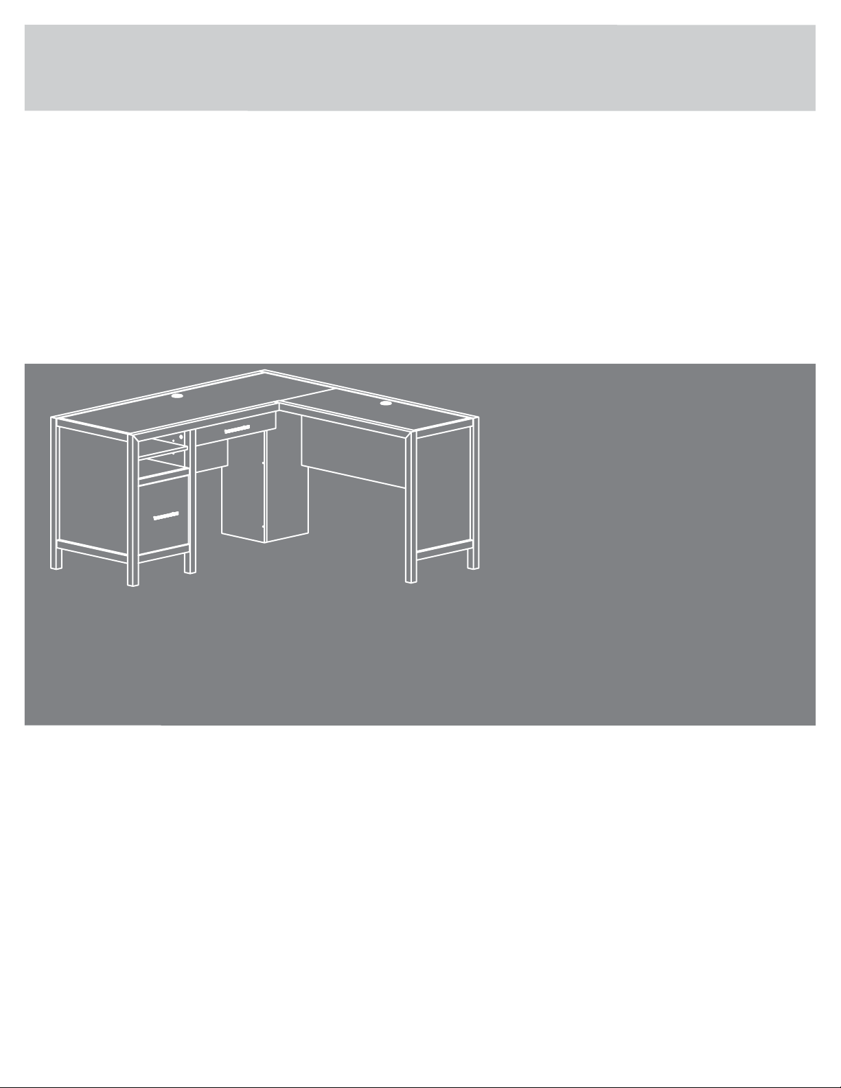
L-Desk
Pacific View Collection |
For all your
newfangled gadgetry.

Table of Contents Assembly Tools Required
Part Identification
Hardware Identification
Assembly Steps
Français
Español
Safety
Warranty
Hammer
Not actual size
No. 2 Phillips Screwdriver
Tip Shown Actual Size
2-3
4-5
6-51
52-57
58-64
65-66
67
Page 2
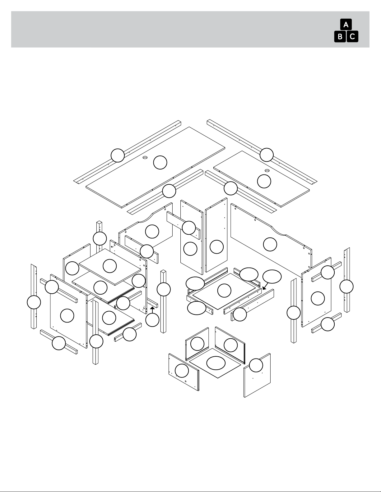
Part Identification
åWhile not all parts are labeled, some of the parts will have a label or an inked letter on the edge
to help distinguish similar parts from each other. Use this part identification to help identify similar parts.
A RIGHT PEDESTAL END (1)
B LEFT PEDESTAL END (1)
B55 PENCIL DRAWER BOTTOM (1)
C DESK TOP (1)
D RETURN TOP (1)
D28 FILE RIGHT DRAWER SIDE (1)
D29 FILE LEFT DRAWER SIDE (1)
D78 FILE DRAWER BACK (1)
D266 PENCIL RIGHT DRAWER SIDE (1)
D267 PENCIL LEFT DRAWER SIDE (1)
D563 PENCIL DRAWER BOX FRONT (1)
D564 PENCIL DRAWER BACK (1)
D707 FILE DRAWER BOTTOM (1)
E RETURN RIGHT END (1)
F RETURN MODESTY PANEL (1)
G DESK MODESTY PANEL (1)
H FILE DRAWER FRONT (1)
J PEDESTAL BOTTOM (1)
K RETURN SIDE MOLDING (2)
L PEDESTAL END MOLDING (3)
M FRONT BOTTOM MOLDING (1)
N FRONT TOP MOLDING (1)
O
FRONT RETURN MOLDING (1)
P DRAWER MOUNT (2)
Q ADJUSTABLE SHELF (1)
R SHELF (1)
S LARGE SUPPORT PANEL (1)
T SMALL SUPPORT PANEL (1)
U RIGHT FRONT/LEFT REAR LEG (2)
V LEFT FRONT/RIGHT REAR LEG (2)
W RIGHT FRONT PEDESTAL LEG (1)
X RIGHT REAR PEDESTAL LEG (1)
Y BACK (1)
Z PENCIL DRAWER FRONT (1)
AA BACK TOP MOLDING (1)
BB BACK RETURN MOLDING (1)
CC SHELF MOLDING (1)
Part Identification Now you know
our ABCs.
Page 3
A
B
C
D
E
F
G
H
JK
L
M
NO
P
Q
R
ST
U
V
W
X
Y
Z
AA BB
CC
B55
D707
D266
D267
D78 D28
D29
D564
U
LV
K
P
D563
L

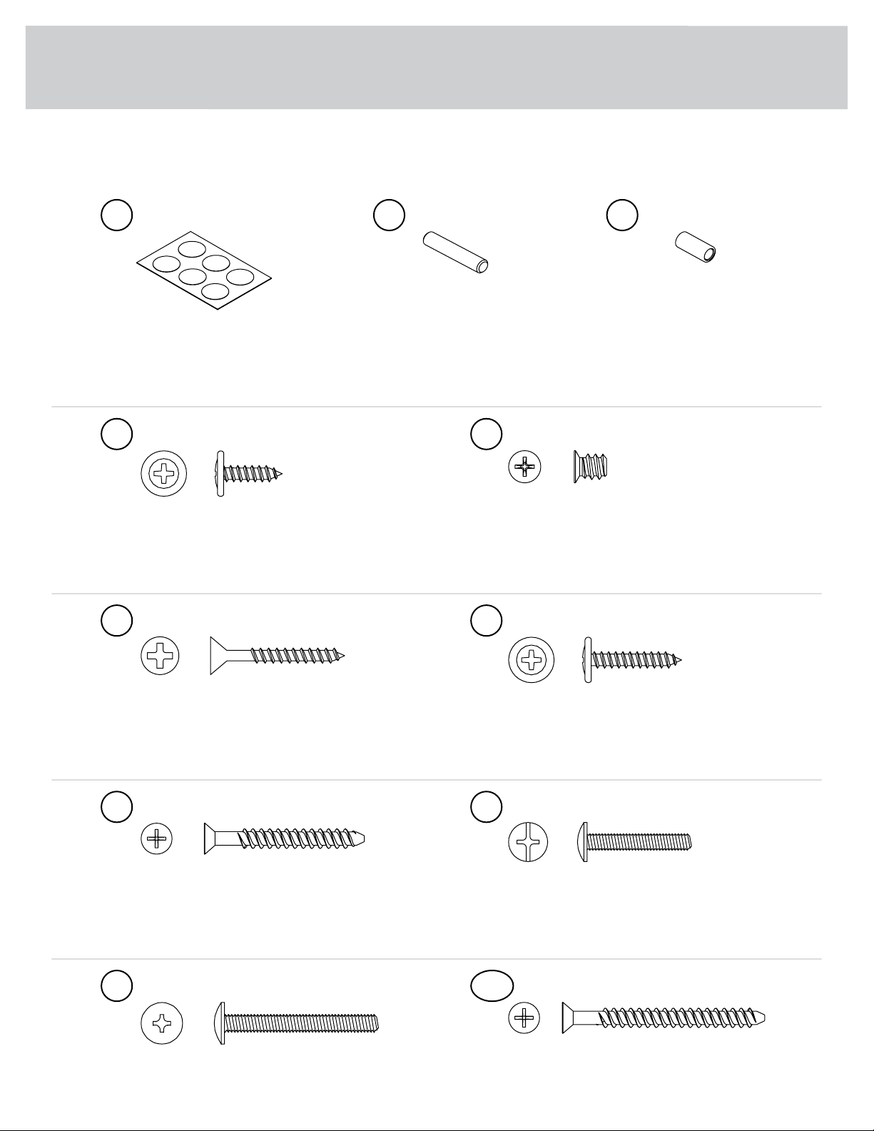
Hardware Identification
åScrews are shown actual size. You may receive extra hardware with your unit.
Page 4
40CA CABINET RIGHT - 1 40CB CABINET LEFT - 1 40CC DRAWER RIGHT - 1 40CD DRAWER LEFT - 1
(EXTENSION SET SHOWN SEPARATED)
EXTENSION SLIDE - 2
40MC
EXTENSION RAIL - 2
40MA 10A SLIDE CAM - 2 FILE ROD - 2
8B
FILE GLIDE - 2
15B HIDDEN CAM - 57
1F CAM DOWEL - 22
2F CAM SCREW - 35
8F
CONNECTOR PLATE - 2
14G10F TWIST-LOCK®
FASTENER - 4 WOOD DOWEL - 17
15F
PULL - 2
190K 29M BUMPER CARD - 1 GROMMET CAP - 2
1P GROMMET - 2
10P
MOLDING
CONNECTOR - 4
16F
Hardware Identification
åScrews are shown actual size. You may receive extra hardware with your unit.
Page 5
BLACK 9/16" LARGE HEAD SCREW - 16
1S 3S GOLD 5/16" FLAT HEAD SCREW - 16
BLACK 1-1/4" FLAT HEAD SCREW - 10
7S BLACK 7/8" LARGE HEAD SCREW - 2
17S
30S BLACK 1-9/16" FLAT HEAD SCREW - 8 GOLD 1" MACHINE SCREW - 2
50S
SILVER 1-1/2" MACHINE SCREW - 2
95S BLACK 1-15/16" FLAT HEAD SCREW - 16
113S
APPLIQUE CARD - 5
93P METAL PIN - 4
1R RUBBER SLEEVE - 4
2R

Hardware Usage Guide
HOW TO USE A HIDDEN CAM & CAM DOWEL
Cam Screw
Hidden Cam
Arrow
Push a HIDDEN CAM into
the part. The arrow in the
HIDDEN CAM must point
toward the hole in the
edge of the board.
Hole
2. 3.
1
2
Insert the CAM SCREW into the HIDDEN CAM.
Tighten the HIDDEN CAM.
HOW TO USE A HIDDEN CAM & CAM SCREW
Turn the CAM SCREW until
the shoulder is against the
surface of the part.
1.
2. Insert the metal end of the CAM
DOWEL into the HIDDEN CAM.
1. Push a HIDDEN CAM into
the part. The arrow in the
HIDDEN CAM must point
toward the hole in the edge
of the board.
Hole
Arrow
Metal end
Hidden Cam
Cam Dowel
Start Tighten
Arrow
Minimum
190 degrees
Caution
Risk of damage or
injury. HIDDEN CAMS
must be completely
tightened. HIDDEN
CAMS that are not
completely tightened
may loosen, and parts
may separate. To
completely tighten:
Arrow
Maximum
210 degrees
3.
Page 6

Step 1
Look for this icon. It means a video assembly tip is
available
å Assemble your unit on a carpeted floor or on the empty
carton to avoid scratching your unit or the floor.
å Push six HIDDEN CAMS (1F) into the long edges of the
RETURN RIGHT END (E).
å Push two HIDDEN CAMS (1F) into the short edge of the
RETURN RIGHT END (E). Then, insert the metal end of a
CAM DOWEL (2F) into each HIDDEN CAM.
Page 7
1
Do not tighten the HIDDEN CAMS in this step.
E
1F
Arrow
1F
Arrow
Arrow
1F
2F
Metal end

å Fasten the RETURN SIDE MOLDINGS (K) to the RETURN RIGHT
END (E). Use four BLACK 1-1/4" FLAT HEAD SCREWS (7S).
å NOTE: Be sure to position each MOLDING exactly as shown.
å NOTE: Do not overtighten the SCREWS into the MOLDING.
Step 2
Page 8
E
K
The MOLDING
will overhang the
edge of the END.
These surfaces
should be even.
K
The hole is closer
to this edge.
The hole is closer
to this edge.
BLACK 1-1/4" FLAT HEAD SCREW
(4 used in this step)
7S
Edge with
CAM DOWELS


å Gently tap two MOLDING CONNECTORS (16F) into the
notches in the LEGS (U and V).
Step 4
Page 10
16F
16F
Flat end
Flat end
Use your hammer to gently tap the MOLDING
CONNECTORS (16F) into the notches in the LEGS.
U
V
Other ABC Design Indoor Furnishing manuals

Popular Indoor Furnishing manuals by other brands


Coaster
Coaster 4799N Assembly instructions

Stor-It-All
Stor-It-All WS39MP Assembly/installation instructions

Lexicon
Lexicon 194840161868 Assembly instruction

Next
Next AMELIA NEW 462947 Assembly instructions

impekk
impekk Manual II Assembly And Instructions

Elements
Elements Ember Nightstand CEB700NSE Assembly instructions


