Abicor Binzel TH6D Manual

T E C H N O L O G Y F O R T H E W E L D E R ´ S W O R L D .
www.binzel-abicor.com
EN Instruction leaflet /DE Beipackzettel
EN Sensor support / DE Sensorhalterung
Sensorhalterung
HINWEIS/NOTICE
• Vor der Installation des Optischen Sensors lesen Sie die zugehörige Betriebsanleitung sorgfältig
durch. Sie vermittelt Ihnen Informationen, die für einen störungsfreien und sicheren Betrieb erforderlich
sind.
• Diese finden Sie im Lieferumfang des Optischen Sensors.
Fig. / Abb. 1 Komponenten Sensorhalterung
-X
+X
Drehachse A
Drehachse B
123456
78
9
Rotation axis B
Rotation axis A

Instruction leaflet
EN DE
1Optical sensor TH6D Optischer Sensor TH6D
2Fork head Gabelkopf
3Supporting arm (isolated version) Haltearm (isolierte Ausführung)
4Support Halterung
5Cable duct Kabelführung
6Robot Roboter
7Sensor support compl Sensorhalterung kpl.
8iCAT iCAT
9Welding torch Schweißbrenner

Instruction leaflet
EN
Sensorhalterung/Sensor support
HINWEIS/NOTICE
• Before installation of the optical sensor read the corresponding operating instructions carefully. They
provide you with all the information you need for trouble-free and safe operation.
• The operating instructions are included in the scope of delivery of the optical sensor.
Fig. / Abb. 2 Components of sensor support
-X
+X
Drehachse A
Drehachse B
123456
78
9
Rotation axis B
Rotation axis A

Instruction leaflet
DE
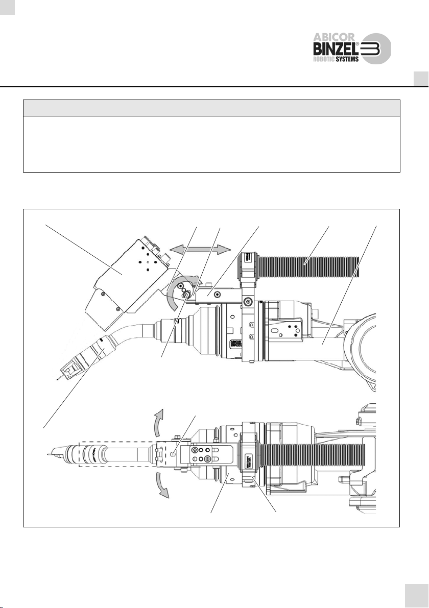
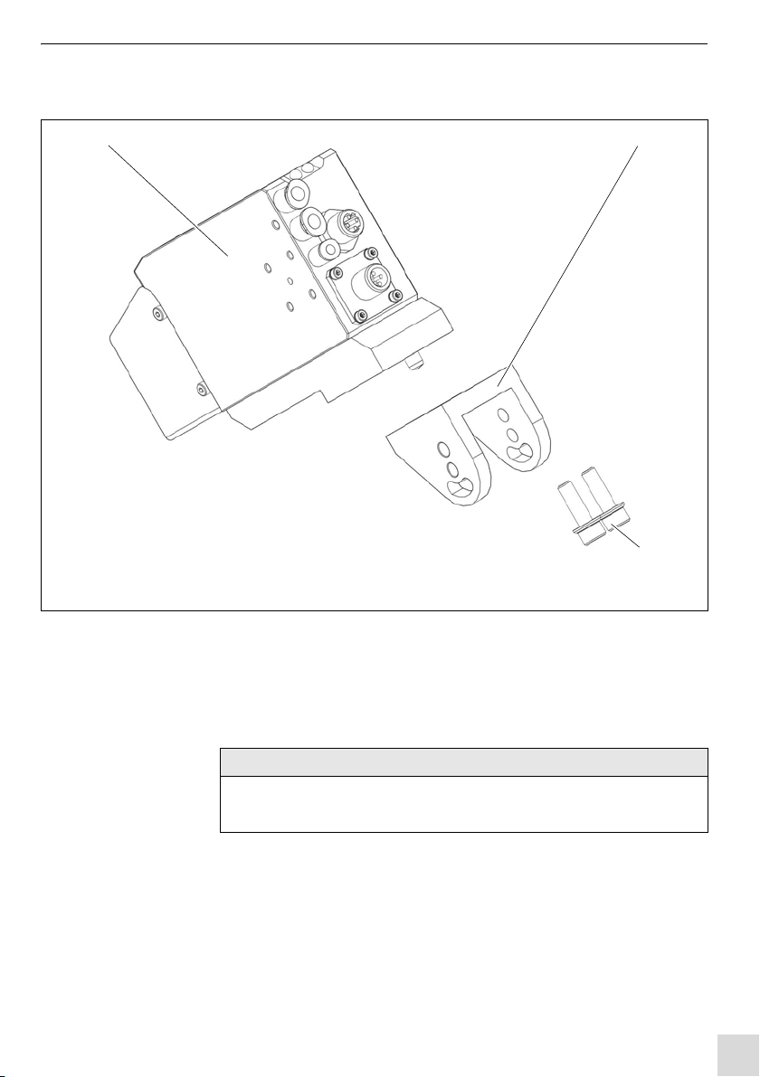
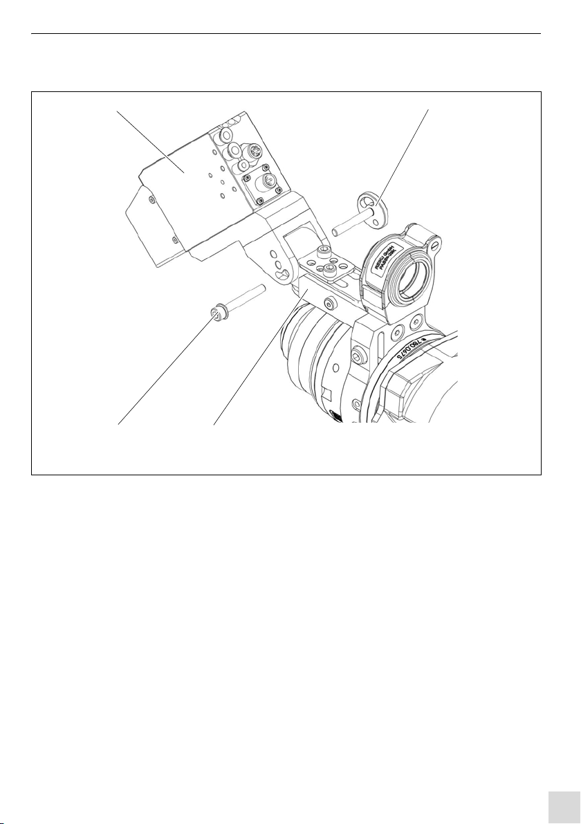
Die Halterung (4) ist in den Achsen A und B sowie in den Richtungen +X und -X verstellbar.
Es können alle Brennerhälse der Serien ABIROB®Aund W(Standard Ausführung, alle Winkel) verwendet
werden. Für die Sonderbrenner-Geometrien sind weitere Halterungen (4) auf Anfrage verfügbar.
Der Sensor (1) dient zur optischen Nahtführung des Schweißbrenners beim Schweißen.
Zur Nahtführung wird mit mehreren Lichtbalken die Nahtform am Fügestoß berührungslos abgetastet. Die
aktuelle Nahtposition, Informationen über Spaltmaß und Kantenversatz am Fügestoß sowie die
Orientierung des Schweißwerkzeugs relativ zur Bauteiloberfläche werden als Messwerte erfasst und an die
Robotersteuerung gesendet. Das Messprinzip mit drei Linien liefert zusätzlich auch die Neigung in
Vorschubrichtung und den Drehwinkel an die jeweilige Maschinen- oder Robotersteuerung.
EN
The support (4) can be adjusted in the axes A and B as well as in the directions +X and -X.
All torch necks of series ABIROB®Aand W(standard version, all angles) can be used. For the geometries
of the special torches there are further supports (4) available on request.
The sensor (1) is designed for the optical seam tracking of the welding torch during welding.
One or more light beams are used during the seam tracking to sense the shape of the seam along the joint
without actually touching it.. Key variables - the current seam position, gap dimensions, joint edge offset as
well as the positioning of the welding tool relative to the workpiece surface - are recorded and transmitted
to the robot controls. The measuring principle with three lines provides additionally the inclination in the feed
direction and the rotation angle at the corresponding machine and robot control system.

DE - 5
Sensorhalterung 1 Übersicht Sensorhalterung
DE Montageanleitung
1 Übersicht Sensorhalterung
1Optischer Sensor TH6D
mit Anbauteilen
2Zylinderkopfschraube
DIN 912 M6x30 (2Stk)
3Druckstück
4Spannschelle NW
23-29 (Kabelführung)
5Halterung
6Zylinderkopfschraube
DIN 912 M8x16
7Halterung kpl. iCAT
8Zylinderkopfschraube
DIN 912 M6x45 mit Scheibe
9Zentrierbolzen
10 Passschraube
M5x40
Abb. 2 Übersicht Sensorhalterung
123
4
5
6
7
89
10
HINWEIS
• Beachten Sie: max. Anzugsmoment von 12 Nm der Zylinderschrauben.

DE - 6
2 Sensorhalterung montieren Sensorhalterung
2 Sensorhalterung montieren
2.1 1. Schritt
1Adapterplatte (2) mit Zylinderschrauben (4) an Sensor (1) befestigen.
1Optischer Sensor TH6D
2Adapterplatte
3Zentierstift 4Zylinderschraube DIN 912 M3x10 (4Stk)
Abb. 3 Schritt 1
1 2
3
4
HINWEIS
• Beachten Sie: max. Anzugsmoment 0,56 Nm der Zylinderschrauben (4).
BAL von Optischer Sensor TH6D, Kap. 4.4.2
• Achten Sie auf eine gerade Ausrichtung von Sensor und Adapterplatte.

DE - 7
Sensorhalterung 2 Sensorhalterung montieren
2.2 2. Schritt
1Gabelkopf (2) und Zylinderschrauben (3) an TH6D (1) befestigen.
Bei Bedarf Sensor mit Hilfe des Langloches noch mittig ausrichten.
BAL von Optischer Sensor TH6D
1Optischer Sensor TH6D mit
Adapterplatte
2Gabelkopf 3Zylinderschraube DIN 912 M4x12 (2 Stk)
Abb. 4 Schritt 2
1 2
3
HINWEIS
• Beachten Sie: max. Anzugsmoment von 5 Nm der
Zylinderschrauben (3).

DE - 8
2 Sensorhalterung montieren Sensorhalterung
2.3 3.Schritt
1Sensorhalterung (1) auf iCAT in Montagerichtung bis Anschlag
aufschieben.
2iCAT (3) mit Zylinderschrauben (4) an Sensorhalterung (1) sichern.
3Zylinderschraube (2) anziehen.
4Zylinderschrauben (4) fest anziehen.
1Sensorhalterung (vormontiert)
2Zylinderschraube DIN 912 M8x12
3iCAT 4Zylinderschraube DIN 912
M4x12 (2Stk)
Abb. 5 Schritt 3
12 3
4
Montagerichtung
Anschlagsfläche
HINWEIS
• Beachten Sie: max. Anzugsmoment von 3 Nm der
Zylinderschrauben (2).
• Beachten Sie: max. Anzugsmoment von 12 Nm der
Zylinderschrauben (4).

DE - 9
Sensorhalterung 2 Sensorhalterung montieren
2.4 4. Schritt
1TH6D (1) mit Anbauteilen mittels Zentrierbolzen (2) und
Zylinderschraube (4) an Sensorhalterung (3) befestigen.
2Mittels der zur Verfügung stehenden Justiermöglichkeiten der
Sensorhalterung können Sie den Sensor auf die optimale Position
ausrichten.
Die Sensorposition ist abhängig von verschiedenen Parametern:
Schweißbrennergeometrie, Bauteil etc.
BAL von Optischer Sensor TH6D beachten
1Optischer Sensor TH6D mit
Anbauteilen
2Zentrierbolzen
3Sensorhalterung
4Zylinderkopfschraube
DIN 912 M6x45 mit Scheibe
Abb. 6 Schritt 4
12
34

DE - 10
2 Sensorhalterung montieren Sensorhalterung
2.5 Positionsbohrungen herstellen
Nach dem Einrichten des Sensors sollte dieser mittels den mitgelieferten
Passchrauben (4), (5) gesichert werden.
1nach der Positionierung des optischen Sensors bohren Sie von Hand zum
fixieren je eine Passbohrung ø5, für die Passschrauben, in die
Sensorhalterung (2).
2Sichern Sie anschließend Sensorhalterung (2) und Gabelkopf (1) mit den
mitgelieferten Passschrauben (4), (5) und Sechskantmuttern (3)
1Gabelkopf
2Sensorhalterung
3Sechskantmutter M5 (2 Stk)
4Passschraube M5x35 D=6
5Passschraube M5x40 D=6
6Zylinderkopfschraube
DIN 912 M6x45 mit Scheibe
Abb. 7 Positionsbohrungen herstellen
12
3
45
6
Bohrungsposition für Sicherung
des Sensorhalters (vorgefertigt)
HINWEIS
• Je nach verwendetem Brennerhals-Typ (22°, 35°, 45° etc.) muss der
Sensor justiert werden. Aus diesen Grund müssen die Bohrungen für die
Passschrauben entsprechend der gewählten Sensorposition gebohrt
werden.

EN - 5
Sensor support 1 Overview Sensor support
EN Assembly instructions
1 Overview Sensor support
1Optical sensor TH6D
with mounting parts
2Cylinder head screw
DIN 912 M6x30 (2 pcs)
3Pressure part
4Clamp NW 23-29
(cable duct)
5Support
6Cylinder head screw
DIN 912 M8x16
7Support compl. iCAT
8Cylinder head screw
DIN 912 M6x45 with washer
9Centring pin
10 Dowel screw
M5x40
Fig. 1 Overview Sensor support
123
4
5
6
7
89
10
NOTICE
• Observe the max. tightening torque of 12 Nm of the cylinder head
screws.

EN - 6
2 Sensor support mounting Sensor support
2 Sensor support mounting
2.1 1 Step
1Fasten the adapter plate (2) with cylinder head screws (4) at the
sensor (1).
1Optical sensor TH6D
2Adapter plate
3Centring pin 4Cylinder head screw DIN 912 M3x10 (4 pcs)
Fig. 2 Step 1
1 2
3
4
NOTICE
• Observe the max. tightening torque of 0.56 Nm of the cylinder head
screws (4).
BAL of the optical sensor TH6D, chap. 4.4.2
• Ensure straight alignment of the sensor and adapter plate

EN - 7
Sensor support 2 Sensor support mounting
2.2 2 Step
1Fasten the fork head (2) and cylinder screws (3) at TH6D (1).
If necessary, align the sensor in the centre using the elongated slot.
BAL of the optical sensor TH6D
1Optical sensor TH6D with
adapter plate
2Fork head 3Cylinder head screw DIN 912 M4x12 (2 pcs)
Fig. 3 Step 2
1 2
3
NOTICE
• Observe the max. tightening torque of 5 Nm of the cylinder
head screws (3).

EN - 8
2 Sensor support mounting Sensor support
2.3 3rd step
1Slide the sensor support (1) onto iCAT in the mounting direction until the
stop.
2Secure iCAT (3) with cylinder head screws (4) at the sensor support (1).
3Tighten the cylinder head screws (2).
4Tighten the cylinder head screws (4) firmly.
1Sensor support (pre-assembled)
2Cylinder head screw DIN 912 M8x12
3iCAT 4Cylinder head screw DIN 912
M4x12 (2 pcs)
Fig. 4 Step 3
12 3
4
Mountingdirection
Contact surface
NOTICE
• Observe the max. tightening torque of 3 Nm of the cylinder
head screws (2).
• Observe the max. tightening torque of 12 Nm of the cylinder head
screws (4).

EN - 9
Sensor support 2 Sensor support mounting
2.4 4 Step
1Fasten TH6D (1) with mounting parts using the centring pin (2) and
cylinder head screw (4) at the sensor support (3).
2Using the available adjustment options of the sensor support the sensor can
be adjusted in the optimum position.
The sensor position depends on different parameters:
welding torch geometry, component etc.
Observe the BAL of the optical sensor TH6D
1Optical sensor TH6D with
mounting parts
2Centring pin
3Sensor support
4Cylinder head screw
DIN 912 M6x45 with washer
Fig. 5 Step 4
12
34

EN - 10
2 Sensor support mounting Sensor support
2.5 Drilling positioning holes
After the set-up, the sensor must be secured by means of the enclosed dowel
screws (4), (5).
1After positioning of the optical sensor drill manually a hole with ø5 for the
dowel screws in the sensor support (2).
2Then secure the sensor support (2) and fork head (1) by means of the
enclosed dowel screws (4), (5) and hexagon nuts (3)
1Fork head
2Sensor support
3Hexagon nut M5 (2 pcs)
4Dowel screw M5x35 D=6
5Dowel screw M5x40 D=6
6Cylinder head screw
DIN 912 M6x45 with washer
Fig. 6 Drilling positioning holes
12
3
45
6
Hole position to secure
the sensor support (pre-fabricated)
NOTICE
• Depending on the torch neck type (22°, 35°, 45° etc.) the sensor must
be adjusted. For this reason the holes for the dowel screws must be
drilled according to the selected sensor position.

EN - 12
2 Sensor support mounting Sensor support
Table of contents
Languages:
Other Abicor Binzel Accessories manuals