2 A-N68SV Series
1.2 Choosing a Computer Chassis
• Choose a chassis big enough to install this motherboard.
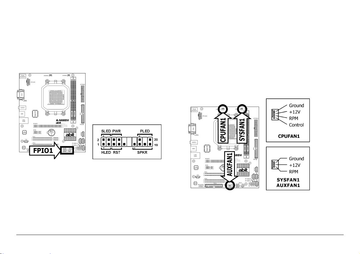
• As some features for this motherboard are implemented by
cabling connectors on the motherboard to indicators and switches
or buttons on the chassis, make sure your chassis supports all the
features required.
• If there is a possibility of adopting some more hard drives, make
sure your chassis has sufficient power and space for them.
• Most chassis have alternatives for I/O shield located at the rear
panel. Make sure the I/O shield of the chassis matches the I/O
port configuration of this motherboard. You can find an I/O shield
specifically designed for this motherboard in its package.
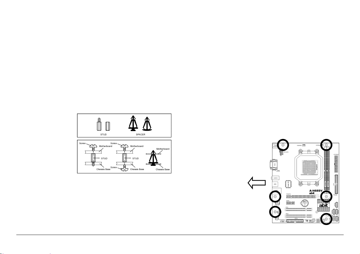
1.3 Installing Motherboard
Most computer chassis
have a base with many
mounting holes to allow
the motherboard to be
securely attached, and at
the same time, prevent
the system from short
circuits. There are two
ways to attach the
motherboard to the
chassis base: (1) with
studs, or (2) with spacers.
Basically, the best way to attach the board is with studs. Only if you are
unable to do this should you attach the board with spacers. Line up the
holes on the board with the mounting holes on the chassis. If the holes
line up and there are screw holes, you can attach the board with studs.
If the holes line up and there are only slots, you can only attach with
spacers. Take the tip of the spacers and insert them into the slots. After
doing this to all the slots, you can slide the board into position aligned
with slots. After the board has been positioned, check to make sure
everything is OK before putting the chassis back on.
※ Always power off the computer and unplug the AC power cord
before adding or removing any peripheral or component. Failing to
so may cause severe damage to your motherboard and/or
peripherals. Plug in the AC power cord only after you have carefully
checked everything.
To install this motherboard:
1. Locate all the screw holes on the motherboard and the chassis
base.
2. Place all the studs or spacers needed on the chassis base and have
them tightened.
3. Face the motherboard’s I/O ports toward the chassis’s rear panel.
4. Line up all the motherboard’s screw holes with those studs or
spacers on the chassis.
5. Install the motherboard with screws and have them tightened.
※ To prevent shorting the PCB circuit, please REMOVE the metal studs
or spacers if they are already fastened on the chassis base and are
without mounting-holes on the motherboard to align with.
This side faces the
chassis’s rear panel.