EG&G 128A Service manual

MODEL
128A
LOCK-IN
AMPLIFIER
SEE SAFETY NOTICE
PRECEDNG SECTION I
;EFORE OPERATING INSTRUMENT
OPERATING
AND
SERVICE
MANUAL

M128A; 9/83·500·MIC
MODEL
128A
LOCK-IN
AMPLIFIER
OPERATING
AND
SERVICE
MANUAL
n
~~
G
BROOKDEAL
ELECTRONICS
~~
.:;;;;;
~
I:..
PRINCETON
APPL/ED
RESEARCH
Copyright
©1983 EG&G PRINCETON APPLIED RESEARCH
Printed
In U.S.A.

SHOULD YOUR EQUIPMENT REQUIRE SERVICE
A. Contact the factory
(6091452-2111)
or
your
local factory
representative to discuss the problem. In many cases it
will be possible to expedite servicing by localizing the
problem to a particular plug-in
circuit
board.
B. If it is necessary to send any equipment back to the fac-
tory, we need the following information.
(1) Model number and serial number.
(2) Your name (instrument user).
(3) Your address.
(4) Address to
which
instrument should be returned.
(5) Your telephone number and extension.
(6) Symptoms (in detail,
including
control
settings).
(7) Your purchase order number for repaircharges (does
not apply to repairs in warranty).
(8) Shipping
instructions
(if you wish to authorize ship-
ment by any method
other
than normal surface
transportation).
C. U.S. CUSTOMERS-·-Ship the equipment being returned
to:
EG&G PRINCETON APPLIED RESEARCH
7 Roszel Road
(Off Alexander Road, East of Route 1)
Princeton, New Jersey
D. CUSTOMERS OUTSIDE OF
U.S.A.-To
avoid delay in
customs clearance of equipment being returned, please
contact the factory or the nearest factory
distributor
for
complete shipping information.
E. Address correspondence to:
EG&G PRINCETON APPLIED RESEARCH
P. O. Box 2565
Princeton, NJ 08540
Phone:
6091452-2111
TELEX: 84 3409
WARRANTY
EG&G PRINCETON APPLIED RESEARCH warrants each in-
strument of
its
manufacture to be free from defects in material
and workmanship. Obligations under
this
Warranty shall be
limited
to replacing, repairing or giving credit for the purchase
price, at our option, of any instrument returned, freight
prepaid, to our factory
within
ONE year of delivery to the
original purchaser, provided
prior
authorization for such return
has been given by our authorized representative.
This Warranty shall not apply to any instrument which our in-
spection shall
disclose
to our satisfaction, has become detec-
tive or unworkable due to abuse, mishandling, misuse, acci-
dent, alteration, negligence, improper installation or
other
causes beyond our control.
Instruments
manufactured by
others, and included in or supplied
with
our equipment, are not
covered by
this
Warranty but carry the original manufacturer's
warranty which is extended to our customers and may be more
restrictive. Certain subassemblies, accessories or corn-
ponents may be specifically excluded from
this
Warranty, in
which case such exclusions are listed in the
Instruction
Manual supplied
with
each instrument.
We reserve the right to make changes in design at any time
without
incurring any obligation to install same on
units
previously purchased.
THERE ARE NO WARRANTIES WHICH EXTEND BEYOND THE
DESCRIPTION HEREIN. THIS WARRANTY IS IN LIEU OF, AND
EXCLUDES ANY AND ALL OTHER WARRANTIES OR REPRE·
SENTATIONS, EXPRESSED, IMPLIED OR STATUTORY, IN·
CLUDING MERCHANTABILITY AND FITNESS, AS WELL AS
ANY AND ALL OTHER OBLIGATIONS OR LIABILITIES OF
EG&G PRINCETON APPLIED RESEARCH, INCLUDING, BUT
NOT LIMITED TO, SPECIAL OR CONSEQUENTIAL DAMAGES.
NO PERSON, FIRM OR CORPORATION IS AUTHORIZED TO
ASSUME FOR EG&G PRINCETON APPLIED RESEARCH ANY
ADDITIONAL OBLIGATION OR LIABILITY NOT EXPRESSLY
PROVIDED FOR HEREIN EXCEPT IN WRITING DULY EXE-
CUTED BY AN OFFICER OF EG&G PRINCETON APPLIED
RESEARCH.

Section
II
III
IV
V
TABLE
OF CONTENTS
CONDENSED
OPERATING
INSTRUCTIONS
CHARACTER
ISTICS
2.1
Introduction
2.2 Specifications
INITIAL
CHECKS
3.1
Introduction
3.2 Equipment Needed
3.3 Procedure
OPERATING
INSTRUCTIONS
4.1
Introduction
4.2 Preliminary Considerations
4.2A
Power Requirements
4.2B Fusing
.....
4.2C Warm-Up Period
4.20
Operating Frequency
4.2E
Grounding...
4.2F Noise
.....
4.3 Operating the Model 128A
4.3A
Introduction..
4.3B Reference Channel
4.3C Signal Channel
4.30
Output
Channel Controls
4.4 Mixer
Function
and Harmonic Sensitivity
4.5 Interface Connector .
4.6 Battery Operation .
4.7 Operation
with
the Internal Reference Oscillator
4.7A
Introduction
4.7B Operation . . . . . . . . . . .
4.7C Installation .
4.8 Operation
with
the Internal Tuned
Amplifier
4.8A
Introduction
4.8B
Operation.........
4.8C Installation .
4.9 More Reference Channel Operating Hints
4.9A
Reference Channel Slewing Rate
4.9B
Phase
Errors
with
Small Reference Signals
ALIGNMENT
.
5.1
Introduction
5.2 Required Equipment
5.3 Preliminary Steps
5.4 Procedure
5.4A
+15 V
Adjust
(R310),
-15
V Check, and +5 V Check
5.4B Reference Board Adjustments
5.4C Signal Board
Adjustment
5.40
Mixer Adjustments
5.4E Other Adjustments
Page
1-1
11-1
11-1
11-1
111-1
111-1
111-1
111-1
IV-l
IV-l
IV-l
IV-l
IV-l
IV-l
IV-l
IV-l
IV-3
IV-5
IV-5
IV-5
IV-6
IV-8
IV-9
IV-10
IV-10
IV-l0
IV-10
IV-10
IV-ll
IV-12
IV-12
IV-13
IV-15
IV-15
IV-15
IV-15
vi
V-l
V-l
V-l
V-l
V-l
V-l
V-3
V-3
V-4
VI
VII
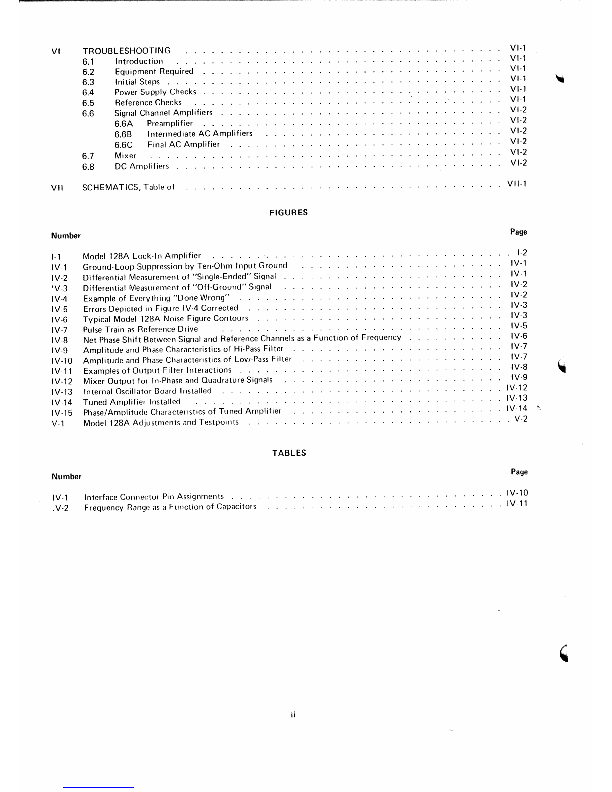
Number
1·1
IV·l
IV-2
'V-3
IV-4
IV-5
IV·6
IV·7
IV-8
IV-9
IV-10
rvu
IV·12
IV-13
IV·14
IV·15
vi
Number
IV-l
.V-2
TROUBLESHOOTING
6.1 Introduction
6.2 Equipment Required
6.3 Initial Steps . . . .
6.4 Power Supply Checks
6.5
Reference Checks
6.6 Signal Channel Amplifiers
6.6A Preamplifier
6.6B Intermediate AC Amplifiers
6.6C Final AC Amplifier
6.7 Mixer
6.8 DC Amplifiers .
SCHEMATICS, Table of
FIGURES
Model 128A Lock-In Amplifier .
Ground-Loop Suppression by Ten-Ohm Input Ground
Differential Measurement of "Single-Ended" Signal
Differential Measurement of
"Off-Ground"
Signal
Example of Everything
"Done
Wrong"
Errors Depicted in Figure IV-4 Corrected
Typical Model
l28A
Noise Figure Contours
Pulse Train as Reference Drive
Net Phase
Shift
Between Signal and Reference Channels as a
Function
of Frequency
Amplitude and Phase Characteristics of Hi-Pass Filter
Amplitude and Phase Characteristics of Low-Pass Filter
Examples of
Output
Filter Interactions . . . . .
Mixer
Output
for In-Phase and Quadrature Signals
Internal Oscillator Board Installed .......
Tuned Amplifier Installed .
Phase/Amplitude Characteristics of Tuned Amplifier
Model 128A Adjustments and
Testpoints
.....
TABLES
Interface Connector Pin Assignments
Frequency Range as a Function of Capacitors
ii
VI-'
VI-'
VI·'
VI-'
VI·'
VI-'
VI·2
VI-2
VI-2
VI-2
VI-2
VI-2
VII·'
Page
.
1-2
IV-l
IV-'
IV-2
IV-2
IV·3
IV·3
IV·5
IV-6
IV-7
IV-7
IV-8
IV-9
IV·12
IV·13
IV·14
. V·2
Page
IV·l0
IV·l1

SAFETY CONSIDERATIONS
A. INTRODUCTION
The apparatus to
which
this
instruction
manual
applies has been supplied in a safe
condition.
This manual
contains
some
information
and warn-
ings that have to be
followed
by the userto ensure
safe operation and to retain the apparatus in a
safe condition. The described apparatus has been
designed
for
indoor
use.
B. INSPECTION
Newly received apparatus should be
inspected
for
shipping damage. If any is noted,
immediately
notify EG&G PARC and file aclaim
with
the car-
rier. The shipping
container
should be saved
for
possible
inspection
by the carrier.
WARNING!
THE PROTECTIVE GROUNDING COULD BE
RENDERED INEFFECTIVE IN DAMAGED AP-
PARATUS.
DAMAGED
APPARATUS
SHOULD NOT BE ·OPERATED UNTIL ITS
SAFETY HAS BEEN VERIFIED BY QUALI-
FIED SERVICE PERSONNEL. DAMAGED AP-
PARATUS WAITING FOR SAFETY VERI-
FICATION SHOULD BE TAGGED TO INDI-
CATED TO A POTENTIAL USER THAT IT
MAY BE UNSAFE AND THAT IT SHOULD
NOT BE OPERATED.
C. SAFETY MECHANISM
As defined in IEC Publication 348 (Safety Require-
ments
for
Electronic
Measuring
Apparatus), the
Model 128A is Class Iapparatus, that is, apparatus
that depends on
connection
to a protective con-
ductor
to earth ground for
equipment
and operator
safety. Before any
other
connection
is made to the
apparatus, the protective earth terminal shall be
connected to a protective conductor. The protec-
tive connection is made via the earth ground
prong of the M128A's power cord plug. This plug
shall only be inserted
into
asocket
outlet
provid-
ed with the required earth ground contact. The
protective action
must
not be negated by the use
of an extension cord
without
aprotective conduc-
tor, or by use of an
"adapter"
that
doesn't
main-
tain earth ground
continuity,
or by any
other
means.
The power cord plug provided is of the type illus-
trated in Figure 1. If
this
plug is
not
compatible
with the available power
SOCkets,
the plug or
power cord should be replaced
with
an approved
type of
compatible
design.
WARNING!
IF IT IS NECESSARY TO REPLACE THE
POWER CORD OR THE POWER CORD
PLUG, THE REPLACEM ENT CORD OR PLUG
MUST HAVE THE SAME POLARITY AS THE
ORIGINAL. OTHERWISE A SAFETY HAZARD
FROM
ELECTRICAL
SHOCK,
WHICH
COULD RESULT IN PERSONAL INJURY OR
DEATH, MIGHT RESULT.
L=
LINE
OR
ACTIVE
CONDUCTOR (ALSO CALLEU
"LlV£"
OR
"HOT")
N=
NEUTRAL
OR
IDENTIFIED
CONDUCTOH
E=EARTH OR SAFETY GROUND
Figure 1. POWER CORD PLUG WITH POl.ARITY INDICATIONS
D. POWER VOLTAGE SELECTION AND
LINE FUSES
Before
plugging
in the
power
cord, make sure that
the
equipment
is set to the voltage of the ac
power
supply.
CAUTION!
THE APPARATUS DESCRIBED IN THIS
MANUAL
MAY BE DAMAGED IF IT IS SET
FOR OPERATION FROM 110 V AC AND
TURNED ON WITH 220 V AC APPLIED TO
THE POWER INPUT CONNECTOR.
Adetailed
discussion
of how to
check
and.tt
nec-
essary, change the power-voltage
setting
follows.
The line voltage is selected by means of a rear-
panel
switch.
FOR SAFETY, UNPLUG THE
POWER CORD WHEN CHECKING THE LINE
VOLTAGE SETTING OR WHEN CHECKING THE
FUSES. FUSES SHOULD ONLY BE CHANGED BY
QUALIFIED SERVICE PERSONNEL WHO ARE
AWARE OF THE HAZARDS INVOLVED. Depend-
ing on the
switch
position,
either
"115"
or
"230"
(both are printed on the
swltchj-wl!l
be
visible
to
the viewer. For operation from a line voltage from
100 V ac to 130 V ac, 50-60 Hz,
"115"
should
show.
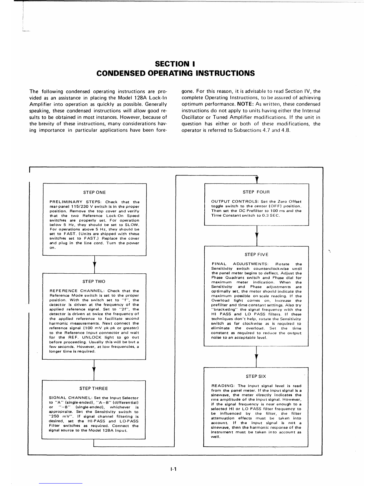
SECTION I
CONDENSED OPERATING INSTRUCTIONS
The
following
condensed
operating
instructions
are pro-
vided as an assistance in placing
the
Model
128A
Lock-In
Amplifier
into
operation
as
quickly
as possible.
Generally
speaking,
these
condensed
instructions
will
allow
good
re-
sults
to be
obtained
in
most
instances.
However,
because
of
the
brevity of
these
instructions,
many
considerations
hav-
ing
importance
in
particular
applications
have
been
fore-
STEP ONE
PRELIMINARY
STEPS;
Check
that
the
rear-panel
115/230
V
switch
is in
the
proper
position.
Remove
the
top
cover
and
verify
that
the
two
Reference
Lock-On
Speed
switches
are
properly
set.
For
operation
below
5
Hz,
they
should
be
set
to
SLOW.
For
operations
above
5
Hz,
they
should
be
set
to
FAST.
(Units
are
shipped
with
these
switches
set
to
FAST.)
Replace
the
cover
and
plug
in
the
line
cord.
Turn
the
power
on.
STEP TWO
REFERENCE
CHANNEL:
Check
that
the
Reference
Mode
switch
is
set
to
the
proper
position.
With
the
switch
set
to
"f",
the
detector
is
driven
at
the
frequency
of
the
applied
reference
signal.
Set
to
"2f",
the
detector
is
driven
at
twice
the
frequency
of
the
applied
reference
to
facilitate
second
harmonic
measurements.
Next
connect
the
reference
signal
(100
m V pk -pk
or
greater)
to
the
Reference
Input
connector
and
wait
for
the
REF.
UNLOCK
light
to
go
out
before
proceeding.
Usually
this
will
be
but
a
few
seconds.
However,
at
low
frequencies,
a
longer
time
is
required.
STEP
THREE
SIGNAL
CHANNE
L:
Set
the
Input
Selector
to
"A"
(single-ended),
"A-B"
(differential)
or
"-B"
(single-ended),
whichever
is
appropraite.
Set
the
Sensitivity
switch
to
"250
mV".
If
signal
channel
filtering
is
desired,
set
the
HI-PASS
and
LO-PASS
Filter
switches
as
required.
Connect
the
signal
source
to
the
Model
128A
Input.
1-1
gone.
For
this
reason,
it is advisable
to
read
Section
IV,
the
complete
Operating
Instructions,
to
be
assured
of achieving
optimum
performance.
NOTE:
As
written,
these
condensed
instructions
do
not
apply
to
units
having
either
the
Internal
Oscillator
or
Tuned
Amplifier
modifications.
If
the
unit
in
question
has
either
or
both
of
these
modifications,
the
operator
is
referred
to
Subsections
4.7
and
4.8.
STEP
FOUR
OUTPUT
CONTROLS;
Set
the
Zero
Offset
toggle
switch
to
the
center
(OFF)
position.
Then
set
the
DC
Prefilter
to
100
ms
and
the
Time
Constant
switch
to
0.3
SEC.
STEP
FIVE
FINAL
ADJUSTMENTS:
Rotate
the
Sensitivity
switch
counterclockwise
until
the
panel
meter
begins
to
deflect.
Adjust
the
Phase
Quadrant
switch
and
Phase
dial
for
maximum
meter
indication.
When
the
Sensitivity
and
Phase
adjustments
are
optimally
set,
the
meter
should
indicate
the
maximum
possible
on-scale
reading.
If
the
Overload
light
comes
on,
increase
the
prefilter
and
time
constant
settings.
Also
try
"bracketing"
the
signal
frequency
with
the
HI
PASS
and
LO
PASS
filters.
If
these
techniques
don't
help,
rotate
the
Sensitivity
switch
as
far
clockwise
as is
required
to
eliminate
the
overload.
Set
the
time
constant
as
required
to
reduce
the
output
noise
to
an
acceptable
level.
STEP SIX
READING:
The
input
signal
level
is
read
from
the
panel
meter.
If
the
input
signal
is a
sinewave,
the
meter
directly
indicates
the
rms
amplitude
of
the
input
signal.
However,
if
the
signal
frequency
is
near
enough
to
a
selected
HI
or
LO
PASS
filter
frequency
to
be
influenced
by
the
filter,
the
filter
attenuation
effects
must
be
taken
into
account.
If
the
input
signal
is
not
a
sinewave,
then
the
harmonic
response
of
the
instrument
must
be
taken
into
account
as
well.

1-2
a:
w
u.
-'
Q.
~
~
~
c
0t
-'
~
co
N
...
-'
W
0
i
...
e
::l
'"
u::

SECTION
II
CHARACTERISTICS
2.1 INTRODUCTION
The
Model
128A
Lock-In
Amplifier
enables
the
accurate
measurement
of
signals
contaminated
by
broad-band
noise,
power
line
pickup,
frequency
drift,
or
other
sources
of
interference. It
does
this
by
means
of an
extremely
narrow
band
detector
which
has
the
center
of
its
passband
locked
to
the
frequency
of
the
signal
to
be
measured.
Because
of
the
frequency
lock
and
narrow
bandwidth,
large
improvements
in signal-to-noise
ratio
can
be achieved,
allowing
the
signal
of
interest
to
be
accurately
measured,
even in
situations
where
it is
completely
masked
by noise.
Signals applied
to
the
input
(single-ended or
differential)
1
routed
through
aseries of amplifiers
which
allow
..rll-scale sensitivity ranges
down
to
one
microvolt.
Switch
selectable low-pass
and
high-pass filters allow
considerable
noise
reduction
ahead
of
the
phase-sensitive
detector.
This
pre-detector
noise
reduction
can
be
further
enhanced
by
making
use of
the
optional
plug-in (internal) selective
amplifier. At
the
phase
sensitive
detector,
the
signal is
compared
with
the
reference
signal derived
from
the
experiment.
Only
those
signal
components
which
are
synchronous
with
the
reference
yield
a
net
dc
detector
output.
Noise
and
other
non-synchronous
signals
do
not
contribute
a
net
dc
output,
but
only
ac
fluctuations
which
can
be
reduced
to
any
arbitrary
value
according
to
the
amount
of filtering
selected
with
the
Time
Constant
switch.
This switch allows
time
constants
as large as
100
seconds
to
be
selected,
with
provision for achieving larger
externally
determined
time
constants
if necessary.
Post-detector
dc
amplifiers drive
the
panel
meter
and
signal
output
connectors.
Other
features
include
provision
for
calibrated
zero
suppression of up to
10
x full scale, a
two-position
dc
prefilter,
and
the
capability
of driving
the
reference
input
the
detector
at
double
the
frequency
of
the
signal
applied to
the
Reference
Input
connector
to
facilitate
second
harmonic
measurements.
An
optional
plug-in
oscillator
(internal)
is available for use in
applications
where
the
experiment
does
not
produce
a
reference
signal itself,
but
is capable
of
being
driven
by a signal
furnished
by
the
Lock-In Amplifier.
With its wide range of capabilities
and
ease
of
operation,
the
Model
128A
Lock-In
Amplifier
should
find
extensive
application
in
situations
where
the
accurate
measurement
of signals is
complicated
by
the
presence
of
noise and
interference.
2.2 SPECIFICATIONS
SIGNAL
CHANNEL
(1) INPUT
TYPE
Single-ended
or
differential
as
selected
by
front-panel
switch.
11-'
(2)
INPUT
IMPEDANCE
100
Mr2
shunted
by
no
more
than
20
pF.
(3)
SENSITIVITY
12 full-scale ranges in
1-2.5-10
sequence
from
1
J.1V
to
250
mV.
(4) FREClUENCY
RANGE
0.5
Hz
to
100
kHz.
(5) COMMON MODE
REJECTION
At least
100
dB
at
1kHz.
(6) MAXIMUM COMMON MODE
VOLTAGE
3 V
pk-pk
to
20
kHz;
then
--6
dB/octave
above
20
kHz.
(7)
DETECTOR
BIAS
Internal
network
allows dc bias
current
of
either
polarity
to
be
provided
at
the
"A"
Input
to
facilitate
operation
with
diode
detectors
which
require
biasing.
(See page VII-3
and
Parts
Location
Diagram
on
page
VII-2.)
(8) NOISE
At 1 kHz
the
signal
channel
noise will
not
exceed
10
nV/H
zY2.
(9) LOW PASS
FILTER
Switch
selectable
6
dB/octave
low-pass filter
which
can be
set
to 3 dB
down
frequencies
of
100
Hz,
10
kHz, or MAX
(greater
than
100
kHz).
(10)
HIGH PASS
FILTER
Switch
selectable
6
dB/octave
high-pass filter
which
can be
set
to
3 dB
down
frequencies
of
50
Hz, 5 Hz,
or MIN
(below
0.5
Hz).
(11)
OVERLOAD
DETECT
Front-panel
indicator
lights if
applied
signal plus noise
is large
enough
to
cause
overload
at
any
of several
critical
overload
monitor
points.
(12)
GAIN
STABILITY

(13) GAIN
LINEARITY
0.05%.
(14)
OVERALL
GAIN ACCURACY
±2%.
REFERENCE
CHANNEL
The
Model
128A
reference channel
automatically
locks
onto
and
tracks
an
applied
reference signal over the
entire
operating
frequency
range of
the
instrument.
As a result,
the
instrument
is
immune
to
frequency
and phase
shifts
as
long as
the
reference and signal to be recovered change
together.
(1)
TRACKING
RANGE
5 Hz to
100
kHz (FAST) or
0.5
Hz to
100
kHz
(SLOW) as
determined
by
the
setting
of
two
internal
switches.
Faster
lock-on
time
and slewing
rate
obtained
with
switches
set
to
FAST
make
this range
preferable
except
when
operating
below 5 Hz.
(2) MODES
Either
of
two
modes, f and 2f, can be selected by
means of a front-panel switch. In
the
"f"
position,
the
phase-sensitive
detector
is driven at
the
same
frequency
as
the
applied reference signal. In
the
"2f"
position,
the
phase-sensitive
detector
is driven at twice
the
frequency
of
the applied reference signal
to
facilitate
second
harmonic
measurements.
(3) INPUT IMPEDANCE
10
Mrl
shunted
by
no
more
than
20
pF.
(4) MINIMUM
REFERENCE
SIGNAL
REQUIREMENT
100
mV pk-pk,
any
waveshape crossing its
mean
only
twice each cycle. Minimum
time
required on
either
side
of
the
mean
is
100
ns.
Amplitude
excursions
must
be at least
50
mV on each side
of
the
mean.
Maximum
input
signal is 5 V (pk-to-rnean}. Best phase
accuracy
is
obtained
with
a 1 V rms sinewave.
(5) LOCK-ON TIME
A
function
of internal
switch
setting
as follows.
Selected
Range Lock-On
Time
SLOW (0.5 Hz to
100
kHz)
20
sec. per
octave
FAST (5 Hz to
100
kHz) 2 sec. per octave
(6) PHASE
Calibrated Phase
controls
allow the phase of
the
reference drive to
the
Phase-Sensitive
Detector
to be
set at any angle relative to
the
input
signal.
The
controls
consist of a Phase Dial with arange of
100°
and a Phase
Quadrant
switch
which
provides
incremental phase shifts of
90°.
The
phase
shift
11-2
accuracy of
the
dial is
better
than
0.2
0over the
entire
frequency
range.
The
resolution
of
the
dial is
better
than
0.10. The
incremental
phase shiffs provided by
the
Quadrant
switch are
accurate
to
0.2°.
The
overall
phase accuracy of
the
instrument,
including
shifts
in
both
the reference and signal channels, is typically
better
than
50.
(7)
DETECTOR
BIAS
Internal
network
allows de bias
current
of
either
polarity
to be provided at
the
REF.
IN
connector
to
facilitate
operation
in
situations
where
the
reference
signal is
taken
from
diodes requiring biasing. (See page
VII-6 and Parts Location Diagram
on
page VII-5.)
PHASE
SENSITIVE
DETECTOR,
DC
AMPLIFIER
(1)
OUTPUT
DRIFT
(2)
OVERLOAD
CAPABILITY
1000
times full scale up to a
maximum
at
the
input
of
650
mV rms. Overload capability is
defined
as
the
ratio, at
the
input
of the Model
128A,
of
the
maximum
pk-pk
non-coherent
signal
which
can be
applied
without
overloading the Model
128A
to
the
pk-pk
coherent
signal required to yield full scale
Model
128A
output.
Note
that,
expressed as
the
ratio
of
the
pk-pk
non-coherent
signal
to
the
rms value of
the
coherent
signal
required
for full-scale
output,
this
number
can be as
great
as
2800.
Maximum
acceptable
signal is a
650
mV rms sinewave.
(3)
NON-COHERENT
REJECTION
50
ppm
maximum.
Non-coherent
rejection is
defined
as
that
offset
which
results
from
applying a
non-coherent
signal having a
pk-pk
amplitude
1000
times
the
pk-pk
amplitude
of
the
coherent
signal
required
to
obtain
full-scale
output.
Example: With a
non-coherent
signal applied having a
pk-pk
amplitude
1000
times
the
pk-pk
coherent
signal
required
to
obtain
full-scale
output,
there
will
occur
an
offset
at
the
output
caused by
the
non-coherent
input
signal.
The
amplitude
of this
offset
will be no
greater
than:
50 X
10-
6X
1000
=50 X
10-
3of f.s.
output
=50 mV (f.s. =1 V)
(4) TIME
CONSTANT
Front-panel switch allows selection of 6
dB/octave
filter
time
constants
of 1 ms, 10 ms, and .1 s
through
100
s in 1-3-10 sequence. Also MIN (time
constant
:::=0.7
ms) and EXT, which allows
time
constants
longer
than
100
s to be achieved by means of
external
capacitors. A
separate
front-panel
toggle switch allows
another
6
dB/octave
filter to be
inserted,
if desired.
This filter has a
time
constant
of
either
100
ms or 1 s,
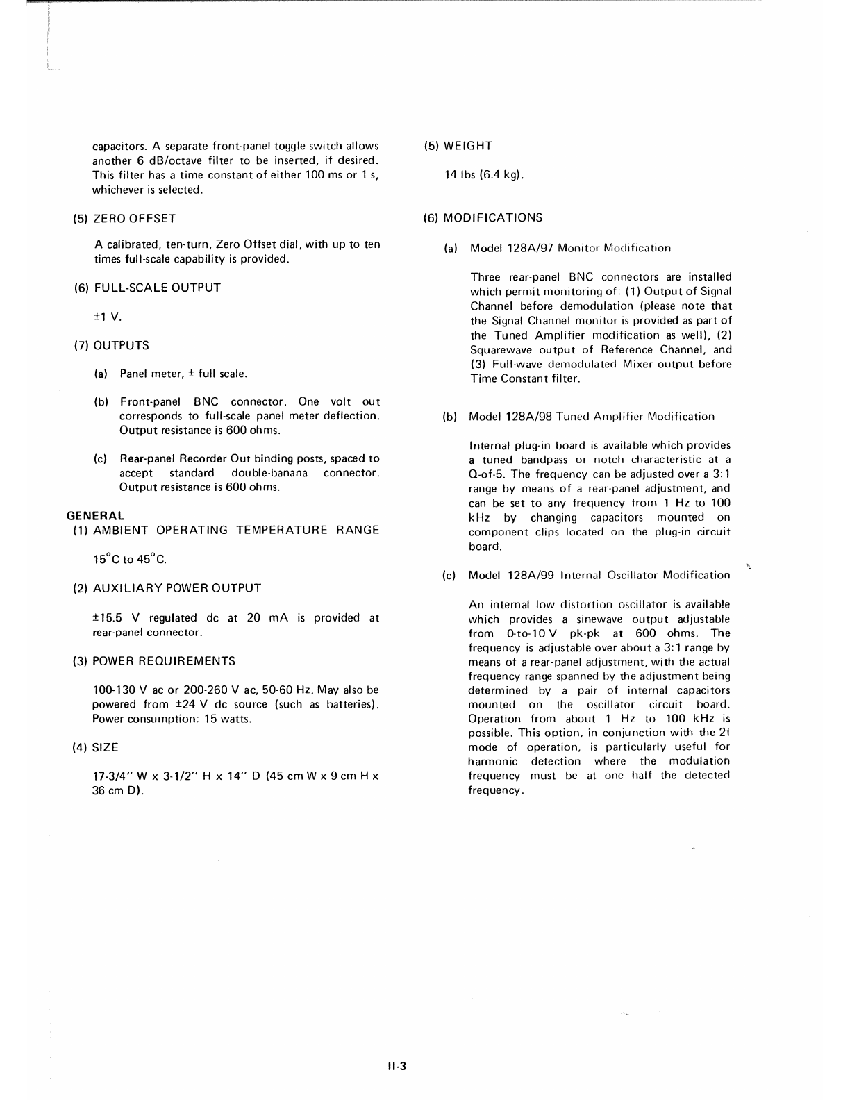
whichever is selected.
(5)
ZERO
OFFSET
A
calibrated,
ten-turn,
Zero
Offset
dial,
with
up to
ten
times full-scale
capability
is provided.
(6) FULL-SCALE
OUTPUT
±1 V.
(7)
OUTPUTS
(a) Panel
meter,
± full scale.
(b)
Front-panel
BNC
connector.
One volt
out
corresponds
to full-scale panel
meter
deflection.
Output
resistance is
600
ohms.
(c) Rear-panel
Recorder
Out
binding posts,
spaced
to
accept
standard
double-banana
connector.
Output
resistance is
600
ohms.
GENERAL
(1) AMBIENT
OPERATING
TEMPERATURE
RANGE
(2)
AUXILIARY
POWER
OUTPUT
±15.5
Vregulated dc
at
20 mA is
provided
at
rear-panel
connector.
(3) POWER
REQUIREMENTS
100-130
Vac
or
200-260
Vac,
50-60
Hz. May also be
powered
from
±24 Vde
source
(such as
batteries).
Power
consumption:
15
watts.
(4) SIZE
17-3/4"
W x
3-1/2"
Hx
14"
D
(45
cm
W x 9 cm H x
36 cm D).
11-3
(5)
WEIGHT
14 Ibs
(6.4
kg).
(6)
MODIFICATIONS
(a) Model
128A/97
Monitor
Modification
Three
rear-panel BNC
connectors
are installed
which
permit
monitoring
of:
(1)
Output
of
Signal
Channel
before
demodulation
(please
note
that
the
Signal Channel
monitor
is provided as
part
of
the
Tuned
Amplifier
modification
as well), (2)
Squarewave
output
of Reference
Channel,
and
(3) Full-wave
demodulated
Mixer
output
before
Time
Constant
filter.
(b) Model
128A/98
Tuned
Amplifier Modification
Internal plug-in
board
is available
which
provides
a
tuned
bandpass
or
notch
characteristic
at a
Q-of-5.
The
frequency
can be
adjusted
over a 3: 1
range by
means
of
arear-panel
adjustment,
and
can be
set
to
any
frequency
from
1 Hz to
100
kHz by changing
capacitors
mounted
on
component
clips
located
on
the plug-in
circuit
board.
(c) Model
128A/99
I
nternal
Oscillator
Modification
An internal low
distortion
oscillator
is available
which
provides asinewave
output
adjustable
from
0-to-l0
V pk-pk
at
600
ohms.
The
frequency
is
adjustable
over
about
a 3: 1 range by
means of a rear-panel
adjustment,
with
the
actual
frequency
range
spanned
by
the
adjustment
being
determined
by a pair of
internal
capacitors
mounted
on
the
oscillator
circuit
board.
Operation
from
about
1 Hz
to
100
kHz is
possible. This
option,
in
conjunction
with
the
2f
mode
of
operation,
is
particularly
useful for
harmonic
detection
where
the
modulation
frequency
must
be at
one
half
the
detected
frequency.

SECTION
III
INITIAL
CHECKS
3.1 INTRODUCTION
The
following
procedure
is
provided
to facilitate initial
performance
checking
of
the
Model 128A. In general, this
procedure
should
be
performed
after
inspecting
the
instrument
for
shipping
damage
(any
noted
to
be
reported
to
the
carrier
and
to
Princeton
Applied
Research
Corporation),
but
before
using
the
instrument
for
experimental
measurements.
Should
any
difficulty
be
encountered
in carrying
out
these checks,
contact
the
factory
or
one
of
its representatives. It
might
be
noted
that
it is
not
the
purpose
of these
checks
to
demonstrate
that
the
instrument
meets
all specifications,
but
rather
simply
to
show
that
it is
functioning
normally.
If normal
indications
e
obtained
for
the
functions
checked,
one
may
reasonably
assume
that
those
functions
which
are
not
checked
are
working
properly
as well.
3.2 EQUIPMENT NEEDED
(1) Sinewave Oscillator
to
provide
a
100
mV rms sinewave
at 1 kHz.
NOTE:
If
the
instrument
to
be
checked
is
equipped
with
the
Tuned
Amplifier
modification,
then
the
oscillator
will have
to
provide a
100
mV rms
sinewave at
the
tuned
frequency.
If
the
instrument
in
question
is
equipped
with
the
Internal Oscillator
modification,
no
external
oscillator will be
required.
Th is applies
whether
or
not
the
unit
is
equipped
with
the
Tuned
Amplifier
modification.
(2) General
purpose
oscilloscope. This
item
is
required
only in
the
case
of
units
having
the
Tuned
Amplifier
modification.
'3) Suitable cables
for
interconnecting
the
above instru-
ments.
3.3 PROCEDURE
(1) Check
the
position
of
the
rear-panel
115/230
switch.
Be sure
the
number
showing
in
the
window
corre-
sponds
to
the
line voltage
to
be used.
(2) With the Power switch
set
to
OFF,
plug in
the
line
cord.
(3)
Set
the
Model
128A
controls
as follows.
Input
Selector: A
Sensitivity:
100
mV
Filters
HI-PASS: MIN.
LO-PASS: MAX.
Phase
Quadrant
switch:
270°
Phase dial:
90°
Mode: f
Zero
Offset
switch:
OFF
(center
position)
111·1
dial:
1.00
(one
turn
from
fully
counterclockwise
position)
Time
Constant:
.3 SEC.
DC Prefilter:
OUT
Reference
Tracking-Rate
switches
(two
internal
switches);
FAST
(unless
unit
is
equipped
with
Tuned
Amplifier'
or Internal Oscillator set for
frequency
below
5 Hz, in
which
case
switches
should
be
set
to SLOW). NOTE:
Instruments
are
normally
shipped
with
these
switches set
to
FAST.
Power.
ON
(4) Applies
only
to
units
not
equipped
with
the
Internal
Oscillator
modification.
If
the
Model
128A
has this
modification,
go
to
step
5.
Connect
the
output
of
the
external
oscillator
(set for
100
mV rms sinewave
out
at 1 kHz)
to
both
the
"A"
and
Reference
Inputs. If
the
unit
in
question
has
the
Tuned
Amplifier
modification,
set
the
oscillator
to
the
tuned
frequency
specified
when
the
unit
was
ordered.
(5) Applies
only
to
units
having
the
Internal Oscillator
modification.
Connect
a
cable
from
the
rear-panel
REF.
OSC.
OUT
connector
to
the
front-panel
"A"
Input.
There
is no
need
to
connect
th is signal to
the
Reference
Input
connector
(labeled MONITOR in
units
equipped
with
the
Oscillator
modification).
The
connection
to
the
Reference
Channel of
the
Model
128A
is
made
internally
at
the
factory.
The
rear-panel
REF.
AM-
PLITUDE
adjustment
should
be
set
so
that
the
amplitude
of
the
signal at
the
REF.
OSC.
OUT
connector
is
100
mV rms. An
accurate
ac
voltmeter
may be useful
for
setting
this
level (units leave the
factory
set
for
a
nominal
100
mV rrns
out).
(6) Applies
only
to
units
having
the
Tuned
Amplifier
modification.
In
the
case
of
units
not
having
this
modification,
go d irectl y
to
step
7.
(a)
Connect
the
oscilloscope to
the
rear-panel SIG.
MON.
connector.
(b)
Vary
the
frequency
of
the
signal applied to
the
"A"
Input
(use
the
rear-panel
REF.
OSC.
FREQ.
ADJ.
control
in
units
equipped
with
an Internal
Oscillator)
for
peak
signal
amplitude
as observed
with
the
oscilloscope.
(7)
Set
the
Phase
Quadrant
switch
to
0°.
Then
adjust
the
Phase dial
for
"0"
panel
meter
indication.
(8)
Set
the
Phase
Quadrant
switch
back
to
270°.
The
panel
meter
should
indicate
full scale to
the
right ±a
few
percent
of full scale.
The
accuracy
of
th is readinq
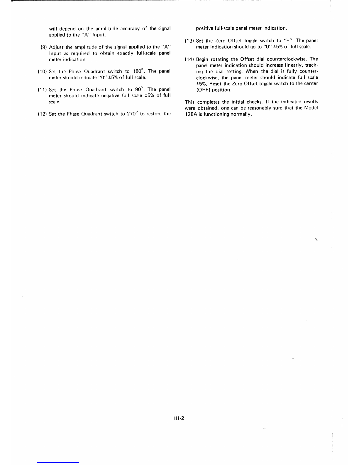
will
depend
on the
amplitude
accuracy of the signal
applied
to
the
"A"
Input.
(9)
Adjust
the
amplitude
of
the
signal applied to
the
"A"
Input
as required to
obtain
exactly
full-scale panel
meter
indication.
(10)
Set
the
Phase
Quadrant
switch to
180°.
The
panel
meter
should
indicate
"0"
±5%
of
full scale.
(11)
Set
the
Phase
Quadrant
switch
to
90°.
The
panel
meter
should
indicate
negative full scale ±5% of full
scale.
(12)
Set
the
Phase
Quadrant
switch to
270°
to restore
the
111-2
positive full-scale panel
meter
indication.
(13)
Set
the
Zero
Offset
toggle switch to "+".
The
panel
meter
indication
should
go to
"0"
±5% of full scale.
(14) Begin
rotating
the
Offset
dial
counterclockwise.
The
panel
meter
indication
should
increase linearly, track-
ing
the
dial setting. When
the
dial is fully
counter-
clockwise,
the
panel
meter
should
indicate full scale
±5%. Reset
the
Zero
Offset toggle switch to
the
center
(OFF)
position.
This
completes
the
initial checks. If
the
indicated results
were
obtained,
one
can be reasonably sure
that
the Model
128A
is
functioning
normally.
SECTION
IV
OPERATING
INSTRUCTIONS
4.1 INTRODUCTION
Even
though
operation
of
the
Model
128A
is
straight-
forward,
there
are a
number
of
factors
of
which
the
operator
should
be aware
to
be assured of achieving
optimum
performance
in all
situations.
This
section
of
the
manual
treats
these
considerations
in
some
detail.
Topics
covered include
grounding,
noise
performance,
harmonic
sensitivity,
operation
in
conjunction
with
the
plug-in
accessories,
and
others.
For
an overall
"quick
look"
at
how
the
instrument
is
operated,
the
operator
is
referred
to
Section
I,
the
condensed
operating
instructions.
4.2
PRELIMINARY
CONSIDERATIONS
4.2A
POWER
REQUIREMENTS
The
Model
128A
requires
100-130
V ac
or
200-260
V ac,
50-60
Hz.
The
power
consumption
is
15
watts.
The
unit
may also be
powered
by
batteries
by
applying
±24 V
to
the
appropriate
pins
of
the
rear-panel octal-
connector
(see
BATTERY
OPERATION,
page
IV-l0).
Arear-panel slide
switch
determines
whether
the
ac
power
circuits
are
connected
for
operation
from
100-130
V or
from
200·260
V.
For
operation
from
100-130
V,
"115"
should
show
in
the
window.
For
operation
from
200-260
V,
"230"
should
show.
4.28
FUSING
The
Model
128A
is
protected
by a single fuse
mounted
on
its rear panel. A
slow-blow
1/4
A fuse is used for
operation
from
115
V. A slow-blow
1/10
A fuse is used for
operation
from
230
V.
It
occasionally
happens
that
a
slow-blow
fuse
fails in
shipment
as a
result
of
shock
and
vibration.
Hence,
if
the
fuse is
found
to be bad
when
the
instrument
is
operated
for
the
first
time
it is advisable to
try
and
change
the
fuse. If
normal
operation
follows,
chances
are
there
are
no
other
problems.
However, if
the
replacement
fuse fails,
there
is
something
wrong
which
will have to be
corrected
before
proceeding.
4.2C
WARM-UP
PERIOD
For
most
applications,
five
minutes.
Where it is
desired
to
achieve
the
best
possible gain
and
output
stability,
allow an
hour.
4.20
OPERATING
FREQUENCY
Although
one
can,
in principle,
make
equally
accurate
measurements
at any
frequency
within
the
operating
range
of
the
instrument,
operation
is
simplest
and
least
subject
to
error
over arange having as its
lower
limit,
perhaps
a few
hundred
Hz,
and
as its
upper,
perhaps
10k
Hz.
At
very low
frequencies,
phase
offsets
occur
which
could
matter
if
one
is
interested
in
the
absolute
phase of
the
input
signal.
Another
problem
of
low
frequency
operation
is
that
of
l/f
noise, including
both
that
which
develops
in
the
Model
128A
and
that
which
originates
in
the
experiment
itself
to
degrade
the
signal-to-noise
ratio
ahead
of
the
lock-in
amplifier. Increased
response
and
settling
time
could
be a
IV-1
significant
problem
if
one
were
operating
in
conjunction
with
the
optional
plug-in
tuned
amplifier.
At high fre-
quencies,
radiation
and
associated
pick-up
tend
to
be
bothersome.
Another
high
frequency
problem
is
that
of
signal
attenuation
as a result
of
the
input
cable
capacitance.
Th is is especially a
problem
when
working
from
a high
source
resistance.
Other
frequencies
to avoid are
60
Hz
and
its
lower
order
harmonics.
By avoiding
these
frequencies,
the
operator
assures
that
he will be
measuring
the
signal
of
interest
only,
uninfluenced
by
power
frequency
pick-up,
either
internal
or
external.
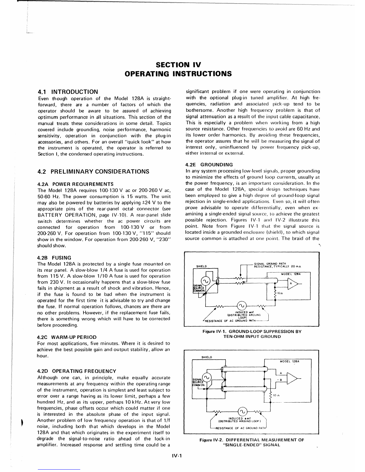
4.2E
GROUNDING
In
any
system
processing low-level signals,
proper
grounding
to
minimize
the
effects
of
ground
loop
currents,
usually
at
the
power
frequency,
is an
important
consideration.
In
the
case of
the
Model
128A,
special design
techniques
have
been
employed
to
give a high
degree
of
ground-loop
signal
rejection
in
single-ended
applications.
Even so, it will
often
prove advisable to
operate
differentiallv.
even
when
ex-
amining
asingle-ended signal
source,
10 achieve
the
greatest
possible
rejection.
Figures IV-l
and
IV-2
illustrate
this
point.
Note
from
Figure IV-l
that
the
signal
source
is
located
inside a
grounded
enclosure
(shield), to
which
signal
source
common
is
attached
at
one
point.
The
braid of
the
/
'U
,
INDUCED emf
(DISTRIBUTED AROUND
LOOP)
RESISTANCE OF AC GROUND
PATH--J
Figure
IV·l.
GROUND·LOOP
SUPPRESSION
BY
TEN-OHM
INPUT
GROUND
SHIELD
l_
10"
L
INDUCE~.mf
'"
(CJSTRIBUTED AROUND LOOP) J
RESISTANCE OF AC GROUND PATH
Figure
IV-2.
DIFFERENTIAL
MEASUREMENT
OF
"SINGLE-ENDED"
SIGNAL

Figure
IV-4.
EXAMPLE
OF
EVERYTHING
"DONE
WRONG"
The
reduction
of
power
frequency
interference
is
not
the
only
benefit
to be
derived
from
proper
grounding
and
differential
operation.
A
much
more
serious
source
of
interference
is
coherent
interference
at
the
signal
frequency
which
results
when
drive signal
current
is
allowed
to
flow
through
the
braid
of
the
signal
cable.
Figures IV-4
and
IV-5
are
provided
to
illustrate
this
problem
and
the
steps
which
can
be
taken
to
prevent
it.
To
begin
with,
Figure
IVA
shows
the
experiment
with
just
about
everything
possible
"done
wrong".
The
lock-in
amplifier
is
operated
single-
ended.
The
ground
connections
at
the
experiment
are
made
to
the
enclosure,
allowing
currents
to
flow
through
it,
and,
in
particular,
the
drive signal
currents
have
the
opportunity
to
flow th rough
the
braid
of
the
signal cable.
The
drive
signal, in
addition
to
providing
the
reference
input
signal
to
the
Model
l28A,
can be
presumed
to
be driving
other
components
of
the
system
as well.
Depending
on
the
nature
of
the
experiment,
these
currents
could
range
from
very
small to
quite
large,
perhaps
even
amperes
if
the
experiment
involves driving a
low
impedance
coil.
Note
that
the
various
loads
for
the
drive
are
represented
by a single
resistor
returned
to
ground
somewhere
on
the
enclosure.
Most-of
this
drive
signal
current
can
be
presumed
to
flow
through
the
shield
back
to
the
drive
signal
source.
However,
asmall
but
significant
part
of it will
flow
through
the
parallel
path
consisting
of
the
braid
of
the
signal cable,
the ten
ohm
resistor,
and
the
braid
of
the
reference
signal
cable.
The
voltage
drop
of
this
current
across
the
resistance
of
the
signal
cable
brai-J,
even
though
attenuated
by
the
ratio
of
the
ten
ohm
resistor
to
the
braid
resistance, can
constitute
a
serious
source
of
interference
at low signal levels,
particular-
ly in
that
this
interference
is
coherent,
in
phase,
and
directly
adds
to
the
signal of
interest.
It is
not
hard
to
envision
situations
where
this
interference
signal
could
well
be larger at
the
Input
of
the
lock-in
amplifier
than
the
signal
of
interest
itself.
signal
cable
is
grounded
directly
to signal
source
common
as
well,
thereby
assuring
that
no signal
currents
or
ground-
loop
currents
will
flow
through
the
shield,
'a
desirable
condition
for
the
best
possible
shielding.
The
Model
l28A
is
operated
single-ended,
using
the
"A"
input.
Note
that
the
"low"
side of
the
amplifier
input
is
not
grounded
to
the
chassis
directly
but
by
way
of
a
ten
ohm
resistor.
Further
note
that
the
braid
of
the
signal
cable
is
returned
to
this
resistor,
and
not
to
the chassis. A
ground
loop
generator
is
indicated
as
being
connected
between
the
chassis of
the
Model
l28A
and
siqnal
source
common.
This
path
would
ordinarily
consist
of
the
ac
ground
"third
wire",
paralleled
by
the
braids
of
other
cables
connecting
the
system
components.
The
ground
loop
generator
will
cause
currents
at
the
power
frequency
to
flow
through
the
braid of
the
signal cable,
through
the
ten
ohm
resistor,
and
back
through
the
ac
wound
path
to
complete
the
loop.
Because
of
the
ten
ohm
ground
employed
in
the
Model
l28A,
these
currents
are
attenuated
over
what
they
would
be if
the
Model
128A
input
were
returned
directly
to
the
chassis.
More
importantly,
most
of
the
ground
loop
signal is
dropped
across
the
ten
ohm
resistor
and
little
across
the
braid of
the
signal
cable,
the
ratio
being
the
ten
ohms
of
the
resistor to
the
10 to
20
milliohms
(typical)
of
the
braid
resistance, As far as
the
input
of
the
Model
l28A
is
concerned,
the
ground
loop
signal is
reduced
by this
ratio,
and
the
ground
loop
interference
is
thus
perhaps
a
factor
of
five
hundred
or
one
thousand
less
than
would
be
the
case
without
the
ten
ohm
qr
ound.
However, in
some
appl
ications, th is
would
not
be
enough.
Figure IV-2
shows
how
this
same
signal
could
be
measured
operating
the
Model
128A
differentially.
In
this
instance,
the
Model
l28A
Input
Selector
is
set
to
"A-B"
and
two
input
cables
are used,
one
connected
to
the
signal
source
and
the
other
to siqnal
source
common.
At
the
source
end,
the
braid
of
both
cables is
returned
to
signal
source
common.
At
the
lock-in
amplifier
end,
the
ten
ohm
ground
serves to
attenuate
the
wound
loop
currents
and
maintain
a
small
ground
loop
signa!
drop
across
the
braids
the
same
as
in Figure
IV-l.
However,
in
the
first
instance,
the
amplifier
"looked"
at
the
potential
difference
between
the
center
conductor
of
the
cable
and
the
braid.
In
the
second,
it sees
the
potential
difference
between
the
"A"
Input
and
"8"
Input.
The
ground
loop
siqnal
current
flowing
in
the
signal
cable
braid is of no
consequence.
The
very high
common
mode
rejection
of
the
amplifier
assures
that
common
mode
power
frequency
pickup
will
not
be a
problem
either.
However,
when
operating
differentially,
it is
important
to
take
a
little
trouble
to assure
that
common
mode
inter-
ference arising in
ground
loops
is
just
that,
that
is,
without
a
significant
differential
component.
This
should
not
prove
a
problem
as
lonq
as
both
signal
cables
follow
the
same
path,
Figure IV-3
shows
the Model
128A
operated
differentially
to
measure
an
"off
~JI
ound
" siqn al.
The
most
important
consideration
in an
application
of this
type
is to be sure
that
the
common
mode
siqnal
component
is
not
so large as
to
exceed
the
common
mode
input
limit
of
the Model
128A.
(See Specs.)
IV-2
DRIVE
~
~:£"
0'"''''''
,.0'"
-1
AS
FUNCTION
OF
EXPERIMENTAL
PARAMETEI
L..-
...I
Figure
IV-3.
DIFFERENTIAL
MEASUREMENT
OF
"0
FF-GROUND"
SIGNAL
DRIVE
LOAD
k=
Boltzmann's
constant
=
1.38
x
10-
2 3 joules/kelvin
T =
absolute
temperature
in kelvins
Rs=Resistance in
ohms
of
the
resistive
component
of
the
impedance
across
which
the
voltage
iii
mea-
sured
B =
Bandwidth
over
which
the
measurement
is
made
Mathematically
expressed,
noise figure
can
be
stated
as:
NF(dB)
=
2010
9 10 Noise
V.olta~_~~g~!':l_~t
of
Amplifier
That
Portion
of
Numerator
Attributable
IV-2
to
Source
Thermal
Noise
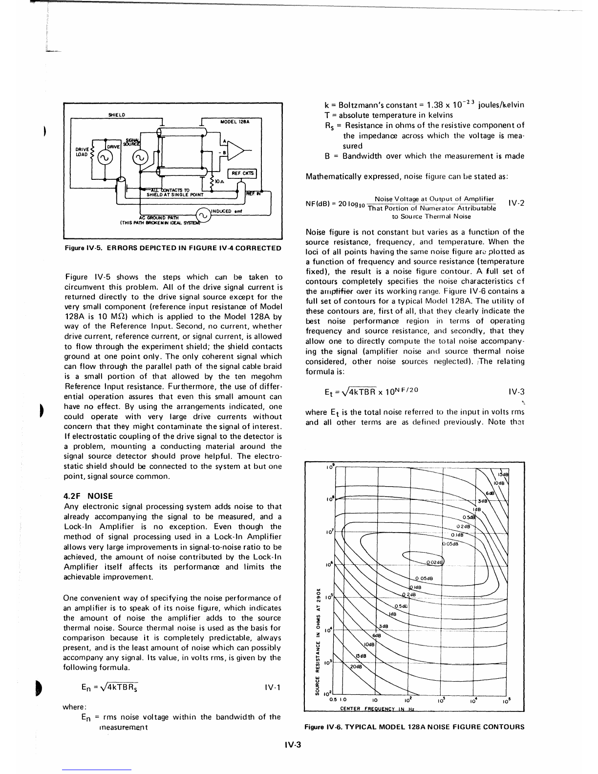
Figure IV-6.
TYPICAL
MODEL
128A
NOISE
FIGURE
CONTOURS
~~
where
Etis
the
total
noise
referred
to
the
input
in volts rrns
and
all
other
terms
are as
defined
previously.
Note
thar
IV-3
10~
Et
=V4kTBR
X
10NF/20
o
11>
N
~
Ul
2
:r
o
~
""
o
z
c(
Ii;
~
0:
""
U
~
~
102::-:~
__
~~---9:::'-'-_--.-l.-
__
.L,
__
--.J
0.5
10
CENTER fR
Noise figure is
not
constant
but
varies as a
function
of
the
source
resistance,
frequency,
and
temperature.
When
the
loci
of
all
points
having
the
same
noise figure are
plotted
as
a
function
of
frequency
and
source
resistance
(temperature
fixed),
the
result
is a noise figure
contour.
A full
set
of
contours
completely
specifies
the
noise
characteristics
cf
the
antpti#er
ruler its
working
range. Figure IV-6
contains
a
full
set
of
contours
for a
typical
Model
128A.
The
utility
of
these
contours
are, first of all,
that
they
clearly
indicate
the
best
noise
performance
region in
terms
of
operating
frequency
and
source
resistance,
and
secondly,
that
they
allow
one
to
directly
compute
the
total
noise
accompany-
ing
the
signal
(amplifier
noise
and
source
thermal
noise
considered,
other
noise
sources
neglected).
.The
relating
formula
is:
IV-l
4.2F NOISE
Any
electronic
signal processing
system
adds
noise to
that
already
accompanying
the
signal to be
measured,
and
a
Lock-In
Amplifier
is no
exception.
Even
though
the
method
of signal processing
used
in a Lock-In
Amplifier
allows very large
improvements
in signal-to-noise
ratio
to be
achieved,
the
amount
of noise
contributed
by
the
Lock-In
Amplifier itself
affects
its
performance
and
limits
the
achievable
improvement.
Figure IV-5
shows
the
steps
which
can be
taken
to
circumvent
this
problem.
All
of
the
drive signal
current
is
returned
directly
to
the
drive signal
source
except
for
the
very small
component
(reference
input
resistance of Model
128A
is 10
MS1)
which
is
applied
to
the
Model
128A
by
way of
the
Reference
Input.
Second,
no
current,
whether
drive
current,
reference
current,
or signal
current,
is
allowed
to
flow
through
the
experiment
shield;
the
shield
contacts
ground
at
one
point
only.
The
only
coherent
signal
which
can
flow
through
the
parallel
path
of
the
signal cable braid
is a small
portion
of
that
allowed by
the
ten
megohm
Reference
Input
resistance.
Furthermore,
the
use of
differ-
ential
operati
on assures
that
even th is small
amou
nt
can
have no
effect.
By using
the
arrangements
indicated,
one
could
operate
with
very large drive
currents
without
concern
that
they
might
contaminate
the
signal
of
interest.
If
electrostatic
coupling
of
the
drive signal
to
the
detector
is
a
problem,
mounting
a
conducting
material
around
the
signal
source
detector
should
prove
helpful.
The
electro-
static
shield
should
be
connected
to
the
system
at
but
one
point,
signal
source
common.
Figure IV-5.
ERRORS
DEPICTED
IN
FIGURE
IV-4
CORRECTED
One
convenient
way
of
specifying
the
noise
performance
of
an
amplifier
is
to
speak
of
its
noise
figure,
which
indicates
the
amount
of noise
the
amplifier
adds
to
the
source
thermal
noise.
Source
thermal
noise is used as
the
basis for
comparison
because
it is
completely
predictable,
always
present,
and
is
the
least
amount
of noise
which
can
possibly
accompany
any
signal. Its value, in volts rms, is given by
the
following
formula.
where:
En =rms noise voltage
within
the
bandwidth
of
the
measurement
IV·3

with
anoise figure of 3 dB,
the
amount
of
noise
contributed
by
the
amplifier
is 1.4
times
the
source
thermal
noise.
At
1.4
times
the
thermal
noise,
the
amplifier
noise
just
begins
to
be
noticeable.
At
lower
noise
figures,
the
amplifier
for
all
practical
purposes
may
be
regarded
as
noiseless.
Generally
speaking,
if
one
can
operate
anywhere
inside
the
3 dB
contour,
amplifier
noise
considerations
may
be
neglected.
As critical as
amplifier
noise is in
certain
applications,
it is
nevertheless
possible
to
overemphasize
its general
impor-
tance.
For
example,
if
the
signal
amplitude
is
significantly
higher
than
the
amplifier
noise,
the
subject
becomes
purely
academic.
Similarly,
if
preamplification
is
provided
ahead
of
the
Model
128A,
with
the
result
that
the
amplified
source
noise at
the
input
to
the
Model
128A
is far
greater
than
the
amplifier
noise,
there
is
little
point
in striving to
operate
inside
the
3 dB
contour
of
the
Model
128A.
However,
where
a
preamplifier
is
used,
it is
important
that
these
same
considerations
be
carefully
evaluated
for
the
preamplifier.
In
other
words,
when
using a
preamplifier,
try
to
operate
inside
the
3 dB
contour
of
the
preamplifier.
A
quick
check
of
Fiqure iV-G
followed
by a
computation
of
the
total
noise
(Equation
IV-3)
should
give
one
arealistic
idea of the
importance
of
amplifier
noise
considerations
to
the
measurement
at
hand.
Where
amplifier
noise is a
consideration,
one
should
try
to
operate
inside
the
3 dB
contour
by
appropriately
adjusting
the
operating
frequency
or
source
resistance.
The
choice
of
operating
frequency
is
usually
determined
by
the
type
of
sensor
used
and
by
the
capabilities
of
the
chopper,
where
one
is
used.
Often,
the ex
perimenter
has
some
control
over
his
choice
of
frequency
and
so can
adjust
things
so
that
he
is
operating
at
the
low
noise
end
of
the
frequency
range
available to
him.
The
situation
with regard to
source
resistance
may
be less
flexible
because
the
source
resistance
is
usually
determined
solely by
the
type
of
sensor
used.
Once
the
commitment
to
a
particular
sensor
has
been
made,
it can be
difficult
to
adapt
the
system
to
another
one.
Hence, in
applications
where
noise is a
uotcntial
problem,
the
choice
of
sensor
should
be
made
carefully
and
with
full regard for
the
noise
characteristics
of the amnlifier.
Two
situations
deserve special
attention,
the
first being
operation
from
a
source
resistance very
much
lower
than
optimum,
and the
second
being
operation
from
a
source
resistance very
much
higher
than
optimum.
In
either
case,
there
may be a
temptation
to
"improve"
the
source
resistance
situation
by
the
use of resistors. In
the
case
of
the low
source
resistance,
one
may
be
tempted
to
connect
a
resistor in series
with
the
source.
In
the
case
of
the
high
source
resistance,
one
may be
tempted
to
connect
a
resistor
in parallel
with
the
source.
Unfortunately,
neither
approach
to
the
problem
does
any
good
and,
in
fact,
both
will
result
in
further
degradation
of
the
signal-to-noise
ratio
ahead
of
the
lock-in
amplifier.
The
series
resistor
adds
its
thermal
noise
to
that
already
accompanying
the
signal.
Although
the
amplifier
shows
a
"better"
noise figure
than
before,
it is
only
because
the
ampl ifier
noise
is
now
less relative to
the
thermal
noise
of
the
combined
resistances (source
plus
IV-4
series
resistor).
The
signal is no larger (in
fact,
it
may
well
be
attenuated),
the
noise is
greater,
and
the
improved
noise
performance
is illusory. Recall
that
noise
figure
only
relates
amplifier
noise
to
thermal
noise, and
does
not
denote
the
absolute
value
of
amplifier
noise.
Connecting
aparallel
resistor
to
lower
a high
source
resistance has a similar
effect.
Even
though
the
thermal
noise
does
go
down,
the
signal
amplitude
goes
down
even
more.
For
example,
if a
source
of
resistance
R
were
paralleled
by
another
resistor
of
the
same
value,
the
signal
ampl
itude
would
go
down
by a
factor
of
two.
However,
the
thermal
noise
would
only
be
reduced
to
.707
of
its initial
value
(thermal
noise
varies
directly
with
the
square
root
of
the
resistance),
with
a
net
degradation
in signal-to-noise
ratio.
In
operating
from
low
source
resistances,
however,
one
can
usually
improve
the
situation
dramatically
by using a
transformer
to
raise
the
source
resistance
seen
by
the
amplifier.
The
improvement
one
obtains
with
a
transformer
is real
because
the
amplitude
of
both
the
signal and
the
noise is
increased
by
the
turns
ratio.
The
source
resistance is
increased by
the
square
of
the
turns
ratio.
For
example,
if
one
had
a
ten
ohm
source,
one
could
use a 1:
100
step-up
transformer,
in
which
case
the
amplifier
would
see a
source
resistance of
100
kn.
At
100
kS1
the
amplifier
adds
little
additional
noise. Even
though
the
thermal
noise
of
the
transformer
adds
to
th at of
the
source,
a very
considerable
improvement
is usually
achieved.
P.A.R.C.
manufactures
a
line of
suitable
signal
transformers,
each
designed
for
optimum
operation
over
agiven
frequency
range. Perfor-
mance
information
can be
obtained
from
the
factory
or
one
of its
representatives.
In using an
external
transformer
in
conjunction
with
'the
Model
128A,
single-ended
operation
of
the
lock-in
amplifier
is advised.
The
extremely
high
inherent
common
mode
rejection
of
the
transformer
makes
differential
operation
of
the
lock-in
amplifier
unnecessary.
When
working
from
a high
source
resistance,
one
could,
in
principle,
use a
transformer
in
the
same
manner
to
improve
noise
performance.
Unfortunately,
practical
transformer
design
considerations
usually
prevent
one
from
doing
so. As
a
result,
the
options
available
to
an
experimenter
working
with
a high
source
resistance device,
such
as a
photo-
multiplier,
are
limited.
Practically
speaking,
the
best
one
can
do
is
to
make
the
load
resistor
as large as possible.
The
larger
the
source
resistor,
the
less
the
shunting
effect
it will
have,
and
the
better
the
signal-to-noise
ratio
at
the
input
of
the
amplifier
will be.
That
this
is so
becomes
clear
when
one
recalls
that
the
signal
amplitude
varies
directly
with
the
load
resistance, while
the
thermal
noise varies
with
the
square
root
of
the
resistance.
Note
that
the
entire
preceding
discussion
of
noise
is based
on
comparing
the
noise
generated
by
the
amplifier
with
the
source
thermal
noise. In
many
situations,
other
types
of
noise
of
interference
may
accompany
the
signal as well and
could
even
dominate
it.
Where
this is
the
case,
the
amplifier
can
only
perform
"better"
than
the
noise figure
contours
indicate
because
the
noise
figures are based
on
acornpari-
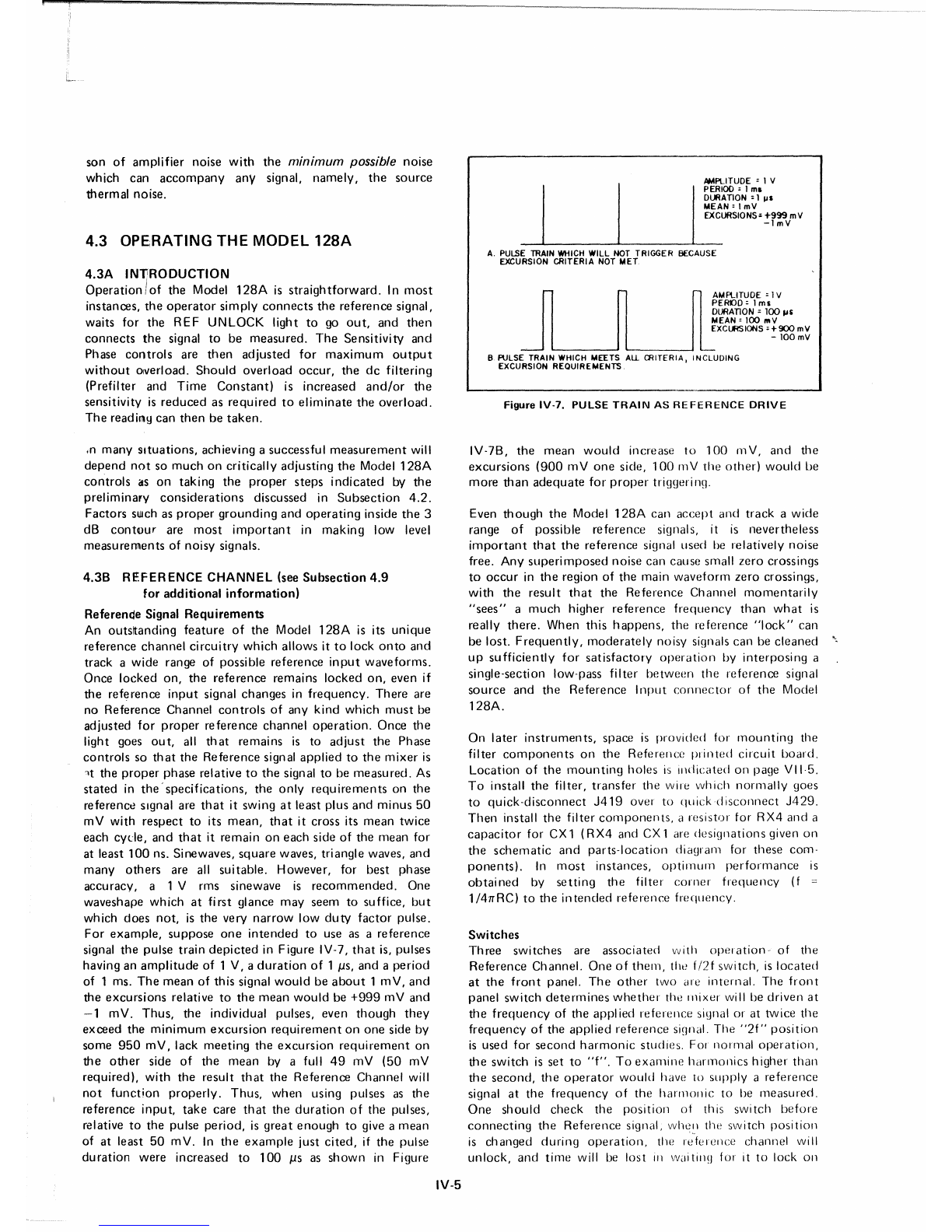
son of
amplifier
noise
with
the
minimum possible noise
which can
accompany
any
signal,
namely,
the
source
thermal
noise.
4.3 OPE;RATING THE MODEL
128A
4.3A
INliRODUCTION
Operation/of
the
Model
128A
is
straightforward.
In
most
instances,
the
operator
simply
connects
the
reference
signal,
waits
for
the
REF
UNLOCK
light to go
out,
and
then
connects
the
signal to be
measured.
The
Sensitivity
and
Phase
controls
are
then
adjusted
for
maximum
output
without
overload.
Should
overload
occur,
the
dc
filtering
(Prefilter and
Time
Constant)
is
increased
and/or
the
sensitivity is
reduced
as
required
to
eliminate
the
overload.
The
readinq can
then
be
taken
.
•n
many
Situations,
achieving asuccessful
measurement
will
depend
not
so
much
on
critically
adjusting
the
Model
128A
controls
as
on
taking
the
proper
steps
indicated
by
the
preliminary
considerations
discussed in
Subsection
4.2.
Factors
such as
proper
grounding
and
operating
inside
the
3
dB
contour
are
most
important
in
making
low level
measurements
of
noisy
signals.
4.38
REFERENCE
CHANNEL
(see
Subsection
4.9
for
additional
information)
Referende
Signal
Requirements
An outsltanding
feature
of
the
Model
128A
is its
unique
reference
channel
circuitry
which
allows it
to
lock
onto
and
track
a
wide
range of possible
reference
input
waveforms.
Once
locked
on,
the
reference
remains
locked
on,
even if
the
reference
input
signal
changes
in
frequency.
There
are
no
Reference
Channel
controls
of
any
kind
which
must
be
adjusted
for
proper
reference
channel
operation.
Once
the
light goes
out,
all
that
remains
is to
adjust
the
Phase
controls
so
that
the
Reference
signal
applied
to
the
mixer
is
-t
the
proper
phase
relative
to
the
signal to be
measu
red. As
stated
in
the'
specifications,
the
only
requirements
on the
reference signal are
that
it swing at least plus
and
minus
50
mV
with
respect
to its
mean,
that
it
cross
its
mean
twice
each cycle,
and
that
it
remain
on
each
side
of
the
mean for
at least
100
ns. Sinewaves,
square
waves, triangle waves,
and
many
others
are all
suitable.
However,
for
best
phase
accuracy,
a 1 V rms sinewave is
recommended.
One
waveshape
which
at
first
glance
may
seem
to suffice,
but
which
does
not,
is
the
very
narrow
low
duty
factor
pulse.
For
example,
suppose
one
intended
to use as a
reference
signal
the
pulse
train
depicted
in Figure IV-7,
that
is, pulses
having an
amplitude
of 1 V, a
duration
of
1
JiS,
and
a
period
of 1 ms.
The
mean
of this signal
would
be
about
1
mV,
and
the
excursions
relative
to
the
mean
would
be
+999
mV
and
-1
mV.
Thus,
the
individual pulses, even
though
they
exceed
the
minimum
excursion
requirement
on
one
side by
some
950
mV,
lack
meeting
the
excursion
requirement
on
the
other
side
of
the
mean
by a full
49
mV
(50
mV
required),
with
the
result
that
the
Reference
Channel
will
not
function
properly.
Thus,
when
using pulses as
the
reference
input,
take
care
that
the
duration
of
the pulses,
relative
to
the
pulse
period,
is
great
enough
to give a
mean
of at least
50
mV.
In
the
example
just
cited,
if the pulse
duration
were
increased to
100
JiS
as
shown
in Figure
IV-5
AMPLITUDE : 1 V
J
~
ER
I
OO
: 1
ml
DURATION:
1
III
MEAN:
ImV
'-
-'-_____
EXCURSIONS:
.!"f~vmv
A. PULSE TRAIN WHICH WILL NOT TRIGGER BECAUSE
EXCURSION CRITERIA NOT MET
J
~
~
A
M
PL
I
TU
D
E
:1V
PEROO:
1ms
~tti~~~~
~~
liS
EXCURSIONS
:+900
mV
- 100 mV
-~
B PULSE TRAIN WHICH MEETS
All.
CRITERIA, INCLUDING
EXCURSION REQUIREMENTS
Figure
IV-7.
PULSE
TRAIN
AS
REFERENCE
DRIVE
IV-7B,
the
mean
would
increase to 100 mV,
and
the
excursions
(900
mV
one
side, 100 mV
the
other)
would
be
more
than
adequate
for
proper
triggerinq.
Even
though
the
Model
128A
can
accept
and
track
a
wide
range
of
possible
reference
siqnals, it is
nevertheless
important
that
the
reference
signal used be relatively
noise
free. Any
superimposed
noise
can
cause small
zero
crossings
to
occur
in
the
region of
the
main
waveform
zero
crossings,
with
the
result
that
the
Reference
Channel
momentarily
"sees"
a
much
higher
reference
frequency
than
what
is
really
there.
When
this
happens,
the
reference
"lock"
can
be lost.
Frequently,
moderately
noisy siqnals
can
be
cleaned
up
sufficiently
for
satisfactory
operation
by
interposing
a
single-section low-pass
filter
between
the
reference
siqnal
source
and
the
Reference
I
nput
connector
of
the
Model
128A.
On
later
instruments,
space
is
provided
for
mounting
the
filter
components
on
the
Reference
printed
circuit
board.
Location
of
the
mounting
holes
is
indicated
on page
VII·5.
To
install
the
filter,
transfer
the wire
which
norrnally
goes
to
quick-disconnect
J419
over
to
quickd
isconnect
J429.
Then
install
the
filter
components,
a
resistor
for
RX4
and
a
capacitor
for CX 1
(RX4
and CX 1 are de
siqnations
given
on
the
schematic
and
parts-location
diagram
for
these
corn-
ponents).
In
most
instances,
optimum
performance
is
obtained
by
setting
the
filter
corner
frequency
(f
::::
1/4rrRC)
to
the
intended
reference
frequency.
Switches
Three
switches
are
associated
with
operation
of the
Reference
Channel.
One
of
them,
the
f/2f
SWitch, is
located
at
the
front
panel.
The
other
two are
internal.
The
front
panel
switch
determines
whether
the
mixer
will be
driven
at
the
frequency
of the
applied
reference
signal or at twice
the
frequency
of
the
applied
reference
signal.
The
"2f"
position
is
used
for
second
harmonic
studies.
For
normal
operation,
the
switch
is
set
to
"f".
To
examine
harmonics
higher
than
the
second,
the
operator
would
have
to
supply
a
reference
signal at
the
frequency
of
the
harmonic
to be
measured.
One
should
check
the
position
of this
switch
before
connecting
the
Reference
signal,
when
the
switch
posi
tion
is
changed
during
operation,
the re"ference
channel
will
unlock,
and
time
will be
lost
III
waitill~]
for it to lock on

5 101
5 10 2
510 2510 2
25°2
FREOUENC.,.
---.
0
0
""-
'SLOW' REF.
r<.:0OE
'FAST' REF
"....,....",
,MODE
-1\
~
I---
\
0
/'
IREF SIG IN IV rml SINE WAVE
SIGNAL IN' 100 mV
,ml
SINEWAVE
IIIII
,
111
,I
,I
'"
-2
0
+2"
°
+1
-1
+3
again. In
most
situations,
the
lost
time
would
be
but
a few
seconds
and
of little
consequence.
However, if
one
were
operating
at
a low
frequency,
it
could
be
lengthy.
The
internal
switches
determ
ine
the
lock-on range,
either
.5
Hz -
100
kHz or 5 Hz
100
kHz. With
these
switches
set
to
either
FAST
or
SLOW,
the
unit
will
lock
onto
reference
signals in
the
frequency
range
of
5 Hz
to
100
kHz
without
difficulty.
However,
only
when
the
switches
are set
to
SLOW will it lock
onto
reference
signals
which
are
below
5
Hz.
The
switches
should
be
set
to
SLOW
only
for
operation
below 5 Hz,
because
the
time
required to achieve
frequency
lock
is longer
with
the
switch
set
to
this
position
than
when
it is
set
to
FAST.
Detector
Biasing
There is no
provision
for
detector
biasing at
the
Reference
Input
by
means
of an
internal
network.
The
network
is
not
provided
but
must
be
furnished
by
the
operator
accord
ing
to
the
impedance
and
voltage
requirements
of his
detector.
The
parts
location
diagram
on page VII-5
shows
where
to
install
the
resistors.
Fi~re
IV-B.
NET
PHASE
SHIFT
BETWEEN
SIGNAL
AND
REFERENCE
CHANNELS
AS A
FUNCTION
OF
FREQUENCY
Phase
Controls
A high
resolution
potentiometer
covering
a range
of
0-to-l00
degrees
works
in
conjunction
with
a
Quadrant
switch
to
determine
the
phase
of
the
synchronous
detection
process
with
respect
to
the
phase of
the
applied
reference
signal.
The Phase Sensitive
Detector
provides
a dc
output
propor-
tional to
the
amplitude
of
the
input
signal. This
output
varies
with
the
cosine
of
the
angle
between
the
reference
and
input
signals. When
the
Phase
controls
are
adjusted
for
maximum
output,
the signal
amplitude
can be read
from
the panel
meter
and
the
phase of
the
signal can be read
from
the
Phase dial.
It may
happen
that
meter
fluctuations
due
to noise will
make
it
difficult
to find the
setting
which
gives
maximum
output.
Where this is the case, it will usually
prove
more
accurate
and
expedient
to
adjust
for
the
null
obtained
when
the
reference
phase is set at 90° relative to
the
signal phase.
Once
the
null is achieved,
the
Phase
Quadrant
switch
can
then
be
rotated
the
one
position
necessary
to
achieve
maximum
output
so
that
the
amplitude
can
be read
from
the
meter.
The
absolute
accuracy
and
resolution
of the Phase
controls
are
stated
in
the
specifications. Figure IV-8
shows
the
typical
net
phase
shift
through
the
unit.
Additional
phase
shifts are
introduced
in
the
Signal Channel at
the
frequency
extremes. Even at middle frequencies,
the
HI-PASS
and
LO-PASS filters can have an
effect
on
the signal phase. A
phase
calibration
can
easily be
made
at any
frequency
by
connecting
the
input
signal (noiseless)
to
both
the Signal
and Reference
Inputs,
followed
by
adjusting
the Phase
controls
for
maximum
output.
The Phase
controls
then
indicate
the
net
phase shitt in
both
the
Signal and
Reference Channels. This
shift
can
then
be
subtracted
from
any
phase
readings
taken
while
operating
at
the
calibration
frequency.
Reference
Monitor
Connector
An
optional
Reference
Monitor
output
can
be
provided
at a
rear-panel
connector.
The
Reference
Channel
output
is
available at this
connector.
This signal is a
square
wave
taken
from
ahead
of
the
Mixer
but
after
the
Phase
Control
circuitry,
and
so is at
the
frequency
of
the
applied
reference
signal
(twice
the
frequency
in
the
case of
"2f"
operation)
and
at
the
phase set
with
the Phase
controls.
Standard
TTL
logic levels are
employed.
Logic
"0"
=
0.2
V
±0.2
V
and
Logic"1"=+3.5V±1
V.
4.3C
SIGNAL
CHANNEL
Introduction
Operation
of
the
Signal
Channel
controls
is
straightforward.
The
Input
Selector
is set to
"A",
"A-B",
or
"-B"
as
appropriate,
the
Sensitivity
switch
is
set
for as
near
full-scale
output
as possible,
and
the
filters are used
to
narrow
the
bandwidth
ahead
of
the
Mixer. In
some
applications,
it
may
be desirable to
incorporate
the
optional
tuned
amplifier
into
the
Signal Channel as well. A
further
discussion of
these
topics
follows.
Input
Selector
Switch
With
this
switch
set to
"A",
the
signal
applied
to
the
"A"
Input
is
processed
by
the
instrument.
Signal
applied
to
the
"B"
Input
is
dead-ended.
Similarly,
when
the
switch
is
set
to
"-B",
the
situation
is the same
except
that
the
roles
of
the
"A"
and
"B"
inputs
are reversed.
Another
difference
is
that
the
"B"
Input
is
180
0
out-of-phase
with
respect
to
the
"A"
Input.
In
other
words,
if a signal
which
yields
positive
output
meter
deflection
when
applied
to
the
-"A"
Input
is
applied
to
the
"B"
Input,
an equal
but
negative reading will
be
obtained.
In
the
"A-B"
position,
the
instrument
operates
differentially,
that
is,
only
the
difference
between
the
signals
applied
to
the
two
inputs
is processed
and
read
out.
As discussed in
Subsection
4.2E,
it is generally
advantageous
to
operate
differentially,
even
when
process-
ing signals
from
asingle-ended
source.
IV-6
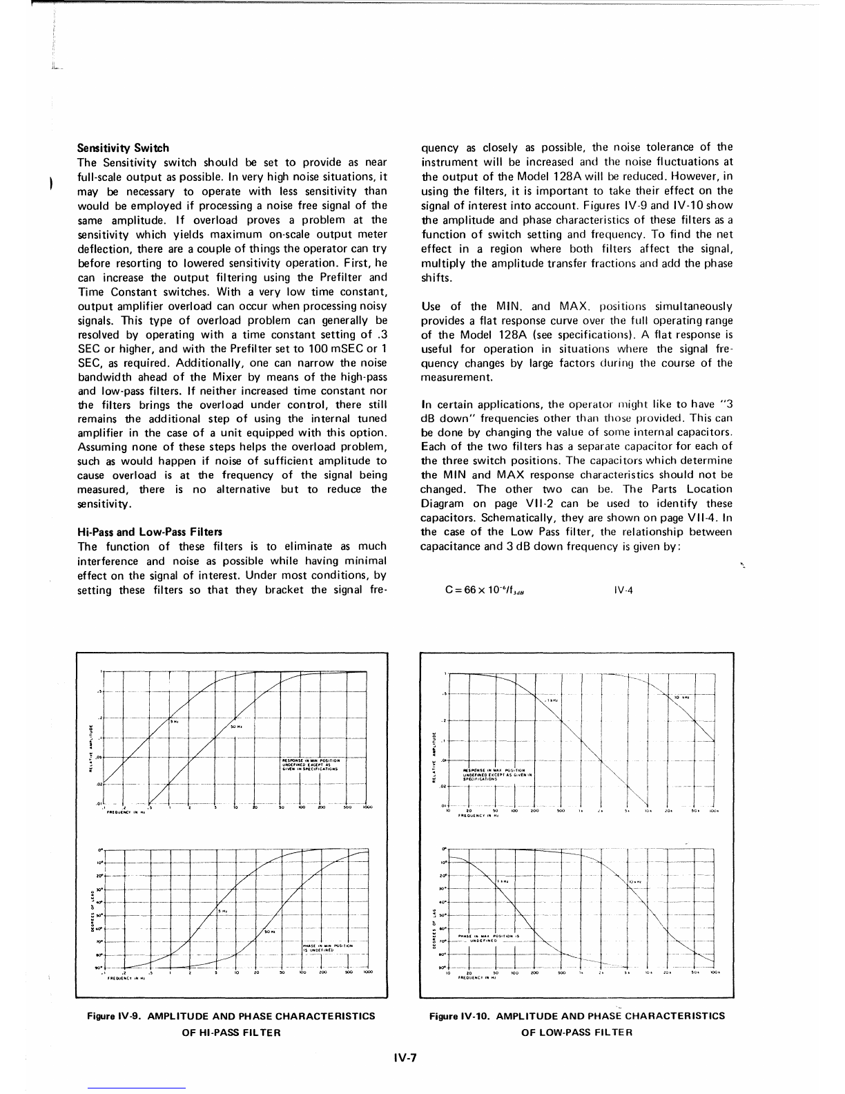
Sensitivity Switch
The
Sensitivity switch
should
be set
to
provide as near
full-scale
output
as possible. In very high noise
situations,
it
may be necessary to
operate
with less sensitivity
than
would be
employed
if processing a noise free signal of
the
same
amplitude.
If
overload proves a
problem
at
the
sensitivity which yields
maximum
on-scale
output
meter
deflection,
there
are a cou pie of th ings
the
operator
can
try
before resorting to lowered sensitivity
operation.
First, he
can increase the
output
filtering using
the
Prefilter and
Time
Constant
switches. With a very low
time
constant,
output
amplifier overload can
occur
when
processing noisy
signals. This
type
of overload
problem
can generally be
resolved by
operating
with
a
time
constant
setting
of
.3
SEC or higher,
and
with
the
Prefilter set to
100
mSEC
or 1
SEC, as required. Additionally,
one
can
narrow
the
noise
bandwidth ahead
of
the
Mixer by means of
the
high-pass
and low-pass filters. If
neither
increased
time
constant
nor
the filters brings
the
overload
under
control,
there
still
remains
the
additional
step
of
using the internal
tuned
amplifier in
the
case
of
a
unit
equipped
with
this
option.
Assuming
none
of
these
steps
helps
the
overload
problem,
such as
would
happen
if noise of
sufficient
amplitude
to
cause overload is at
the
frequency
of
the
signal being
measured,
there
is no alternative
but
to reduce
the
sensitivity.
Hi-Pass and Low-Pass Filters
The
function
of these filters is to eliminate as
much
interference and noise as possible while having minimal
effect
on
the
signal of interest. Under
most
conditions,
by
setting these filters so
that
they
bracket
the
signal fre-
I
v---
~
,._._.
-:
-:
/V
l/
,/
-
V'H'
~H'
,---
--7
f.- /
,~---
V
~~~::;;:~~~~::I~~OSN
.t=t-_=;
.... -. V.-
._-.-
.' ,"'0
quency
as closely as possible,
the
noise
tolerance
of
the
instrument
will be increased and
the
noise fl
uctuations
at
the
output
of the Model
128A
will be
reduced.
However, in
using
the
filters, it is
important
to
take
their
effect
on
the
signal of
interest
into
account.
Figures IV-9 and IV-10
show
the
amplitude
and phase characteristics of these filters as a
function
of
switch
setting
and frequency. To find
the
net
effect
in a region
where
both
filters
affect
the
signal,
multiply
the
amplitude
transfer fractions and add the phase
shifts.
Use of
the
MIN.
and
MAX. POSitions simultaneously
provides aflat response curve over
the
full
operating
range
of
the
Model
128A
(see specifications). Aflat response is
useful for
operation
in
situations
where the signal fre-
quency
changes by large factors during
the
course
of the
measurement.
In
certain
applications,
the
operator
rnight like
to
have
"3
dB
down"
frequencies
other
than
those
provided. This can
be
done
by changing
the
value of some internal capacitors.
Each of
the
two
filters has a
separate
capacitor
for each of
the
three
switch positions.
The
capacitors
which
determine
the
MIN
and
MAX response characteristics
should
not
be
changed.
The
other
two
can be.
The
Parts
Location
Diagram on page VII-2 can be used to
identify
these
capacitors.
Schematically,
they
are
shown
on page VII-4. In
the
case of
the
Low Pass filter,
the
relationship
between
capacitance
and
3 dB
down
frequency
is given by:
IV-4
!:[---~.~
""
--+----'-\---cA"--
to-
----
.1 .2
'R(OO(NC,.frtHI
Ptl,lS(IH"IHPQS,11OJ\l
ISUHO(fIH[O
Figure
rv-s,
AMPLITUDE AND PHASE
CHARACTERISTICS
OF HI-PASS FIL
TER
IV·7
Figure
IV·l0.
AMPLITUDE
AND
PHASE
CHARACTERISTICS
OF LOW-PASS
FILTER
Table of contents
Other EG&G Amplifier manuals

EG&G
EG&G ORTEC 414A Service manual

EG&G
EG&G ORTEC 113 Service manual

EG&G
EG&G ORTEC 427 User manual

EG&G
EG&G ORTEC 855 Service manual

EG&G
EG&G ORTEC 575A Service manual

EG&G
EG&G ORTEC 474 Service manual

EG&G
EG&G 113 Service manual

EG&G
EG&G ORTEC 118A User manual

EG&G
EG&G ORTEC 444 User manual

EG&G
EG&G ORTEC 572 Service manual


