manuals.online logo
Brands
  1. Home
  2. •
  3. Brands
  4. •
  5. Abitana
  6. •
  7. Cables And Connectors
  8. •
  9. Abitana ABI-CP1001S06 User manual

Abitana ABI-CP1001S06 User manual

121204_ABI-CP1001S06&ABI-DC1001S06_QSG_ML
Page 1 N.V. abitana S.A.
ABI-CP1001S06
ABI-DC1001S06
Connectoren voor UTP kabel
Installatiegids
Connecteurs pour câbles UTP
Guide d’installation
Connectivity for UTP cables
Quick Start Guide
1 Benodigd gereedschap / Outillage recommandé / Tools
required
ABI-TA1002 ABI-TA100
1
2 Aansluiting van connectoren / Terminaison du câble / Cable
termination : ABI-CP1001 (*)
1 Verwijder de buitenmantel zoals afgebeeld. Zorg dat de paren
zo goed mogelijk getwist blijven en dat bij het verwijderen van
de buitenmantel de isolatie van de paren niet beschadigd
wordt.
Enlevez la gaine extérieure du câble comme indiqué sur le
dessin ci-dessous. Il faut garder la torsade des paires le
plus loin possible. Il est important de ne pas abîmer
l’isolation des paires lors qu’on enlève la gaine extérieure.
Remove the outer jacket as shown. Keep the pairs twisted
as much as possible. Do not damage the insulation of the
pairs while removing the outer jacket.
2 Druk de draden in de contacten van de connector door middel
van het punchdown gereedschap (ABI-TA1001). Respecteer
nauwkeurig de kleurcodes volgens T568B, zoals aangegeven
op de tekening. De aanbevolen volgorde staat hier eveneens
vermeld.
Insérez les fils dans les contacts du connecteur avec
l’outil ABI-TA1001). Respectez les couleurs selon le code
T568B comme indiqué sur le dessin. La séquence de
terminaison y-est également indiquée.
Push the wires into the corresponding slots, using the
punch down tool (ABI-TA1001). Respect the colour coding
according to T568B and the termination sequence
indicated below.
A
7
8
5
4
1
2
3
6
B
Termination order:
- Slot 7
- Slot 8
- Slot 5
- Slot 4
- Slot 6
- Slot 3
- Slot 2
- Slot 1
Wht/Org
Org
Wht/Grn
Grn
Wht/Brn
Brn
Wht/Blu
Blu
T568B
3 Knip de draden met een scherpe kniptang zo kort mogelijk
tegen de contacten, en plaats het deksel over de contacten.
Plooi indien nodig de kabel naar achter.
Coupez les fils à ras des contacts avec une petite pince
coupante et placez le couvercle. Pliez le câble vers
l’arrière si c’est nécessaire.
Cut the wires with a flush cutter as close as possible to
the IDC slots and click on the wire cap. Afterwards bend
the wire to the back if needed.
Clic
k
3 Voor DC1001 / Pour DC1001 / For DC1001
Klik de connector in de DIN-rail adapter en bevestig de kabel
met de klip en een kabelbindertje.
Insérez le connecteur dans l’adaptateur rail-DIN et fixez le
câble avec le clips et la bride.
Click the terminated connector in the DIN-Rail adaptor and
fix the cable with the clips and a tie-wrap.
Click
Click
Klik de DIN-rail adapter op de DIN-rail door deze te roteren [1].
Voeg de DIN-rail adapter toe aan de rij reeds gemonteerde
adapters door hem bij de laatste bij te klikken [2].
Cliquez l’adaptateur rail-DIN sur le rail en le tournant [1].
Ajoutez l’adaptateur a la rangée en le cliquant sur le
précedent [2].
Click the Comm Center Connector on the DIN-rail by
rotating it [1]. Click the Comm Center Connector into the
previous terminated one by sliding it to the left [2].
Click[1]
Click[2]
60 mm
121204_ABI-CP1001S06&ABI-DC1001S06_QSG_ML
Page 2 N.V. abitana S.A.
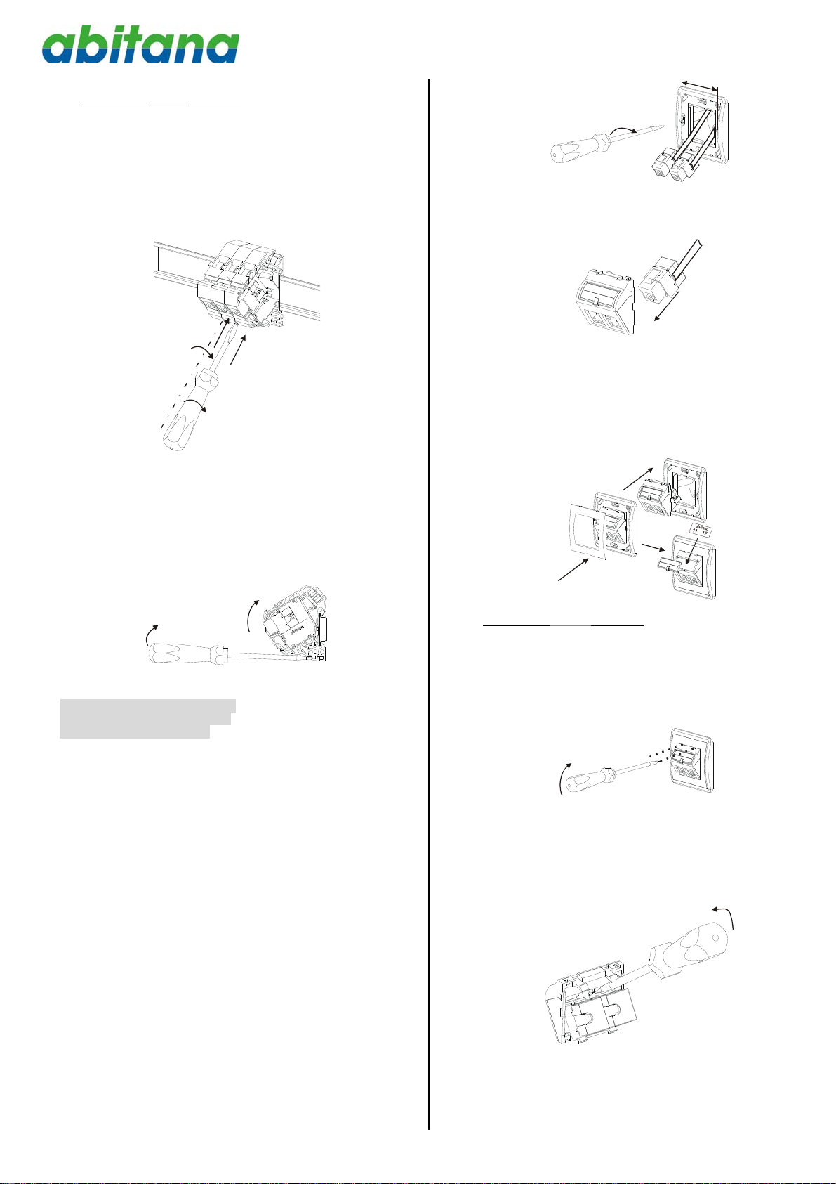
Verwijderen /Enlever / Remove
Duw een smalle schroevendraaier in de opening vooraan
tussen DIN-rail adapters en draai tot deze losklikken. Herhaal
voor beide zijden.
Glissez un tournevis fin dans l’ouverture entre les
adaptateurs rail-DIN, et tournez jusqu'à ce qu’ils se
séparent. Répétez ceci de l’autre côté.
Slide a small screwdriver in the opening between the 2
DIN-rail adapters and turn until the adapters snap out of
each other. Repeat for the other side.
Plaats de schroevendraaier in de opening onderaan de
adapter en gebruik deze als een hefboom om de adapter van
de DIN-rail te klikken.
Mettez le tournevis dans l’ouverture en bas de l’adaptateur
et utilisez le comme levier pour détacher l’adaptateur du
rail-DIN.
Slide the screwdriver in the opening at the bottom of the
Comm Center Connector and use it as a lever to pull out
the connector.
4 Plaatsing in de wandcontactdoor
Installation dans la prise murale
Installation in the wall outlet
De keystone houder laat snelle montage in afdekplaatjes van
verschillende merken toe (lijst op aanvraag beschikbaar) of in
een patchpaneel zoals ABI-HE3002S24. Afhankelijk van het
merk van afdekplaatje kan de montage in de muurdoos lichtjes
afwijken.
Le verrou keystone permet le montage rapide dans les
prises murales d'une multitude de fournisseurs (liste sur
demande) ou dans un panneau de brassage de type
keystone tel que le modèle ABI-HE3002S24. Selon la
marque, le montage dans l’enjoliveur peut être légèrement
différent.
Standard keystone latch makes it compatible with a wide
variety of faceplate brands and finishes (lists available on
demand) or a keystone patch panel like ABI-HE3002S24.
According to the brand, the mounting in the wall outlet
might be slightly different
Schroef de montage ring (ABI-WA1010) op de muurdoos door
middel van de schroeven.
Fixez le cadre de montage (ABI-WA1010) au moyen des vis
de la boite murale.
Fix the mounting ring (ABI-WA1010) by means of the
screw of the wall box.
61mm
Klik de afgemonteerde connector in de adapter.
Insérez le connecteur câblé dans l’enjoliveur.
Click the terminated connector in the wall adapter.
Click
Klik de adapter in de montage ring en klik nadien de afdekplaat
op de montagering. Plaats het identificatie label
Cliquez l’enjoliveur dans l’anneau de montage et puis
cliquez le couvercle sur l’anneau de montage. Insérez
l’étiquette d’identification en dessous la fenêtre.
Click the Wall-adaptor into Mounting-ring. Then click the
cover on the Mounting-ring. Label your Wall-adaptor by
sliding the correct label under the window.
Clic
k
Click
Click
Verwijderen / Enlever / Remove
Schuif de schroevendraaier in de openingen vooraan de
adapter en gebruik deze om de clipsen los te maken.
Mettez le tournevis dans les ouvertures en face avant de
l’enjoliveur et utilisez le pour libérer les clips.
Slide a screwdriver in the small openings at the front of
the wall adapter, and use it to release the clips.
Schuif de schroevendraaier tussen de clips van de connector
en de adapter. Gebruik deze als een hefboom om de clips los
te maken
Mettez le tournevis entre le clips du connecteur et
l’enjoliveur et utilisez le pour libérer les clips.
Slide a screwdriver between clips of the connector and the
adapter and use it to release the clips.
Click

This manual suits for next models

1

Popular Cables And Connectors manuals by other brands

Stelpro SCRG1W0150L0030 owner's manual

Stelpro

Stelpro SCRG1W0150L0030 owner's manual

Grip SWS Assembly and operating manual

Grip

Grip SWS Assembly and operating manual

PCB Piezotronics 023B10 Installation and operating manual

PCB Piezotronics

PCB Piezotronics 023B10 Installation and operating manual

FSR INC. DV-HAS user manual

FSR INC.

FSR INC. DV-HAS user manual

Viessmann 5056 Operation manual

Viessmann

Viessmann 5056 Operation manual

GoMax Electronics SP-5008IZ user manual

GoMax Electronics

GoMax Electronics SP-5008IZ user manual

Cablesson HDelity user manual

Cablesson

Cablesson HDelity user manual

Enerpac VEP-1 instruction sheet

Enerpac

Enerpac VEP-1 instruction sheet

GORE Aerospace Termination instructions

GORE

GORE Aerospace Termination instructions

PCB Piezotronics 010D30 Installation and operating manual

PCB Piezotronics

PCB Piezotronics 010D30 Installation and operating manual

PXM PX725 user manual

PXM

PXM PX725 user manual

ICP DAS USA iWSN-203 quick start

ICP DAS USA

ICP DAS USA iWSN-203 quick start

Volkswagen VAS 5581A/11 operating manual

Volkswagen

Volkswagen VAS 5581A/11 operating manual

Redback A 4498 operating manual

Redback

Redback A 4498 operating manual

Sony CLIE PEGA-HS10 operating instructions

Sony

Sony CLIE PEGA-HS10 operating instructions

Avenview FO-HDM-XX-MM user guide

Avenview

Avenview FO-HDM-XX-MM user guide

LINK-MI LM-SPE108 operating instructions

LINK-MI

LINK-MI LM-SPE108 operating instructions

M-Audio Sound Card MIDI Cable user guide

M-Audio

M-Audio Sound Card MIDI Cable user guide

manuals.online logo
manuals.online logoBrands
  • About & Mission
  • Contact us
  • Privacy Policy
  • Terms and Conditions

Copyright 2025 Manuals.Online. All Rights Reserved.