Absen KL II Series User manual

KL II Series User Manual
Absen Optoelectronic Co.
Ltd.
KL1.2 II / KL1.5 II / KL1.8 II / KL2.5 II

KL II Series User Manual 2
CONTENT
1 PRODUCT INTRODUCTION ...................................................................................................................................................... 6
1.1 Main features ........................................................................................................................................................................... 6
1.2 Product specification ............................................................................................................................................................. 7
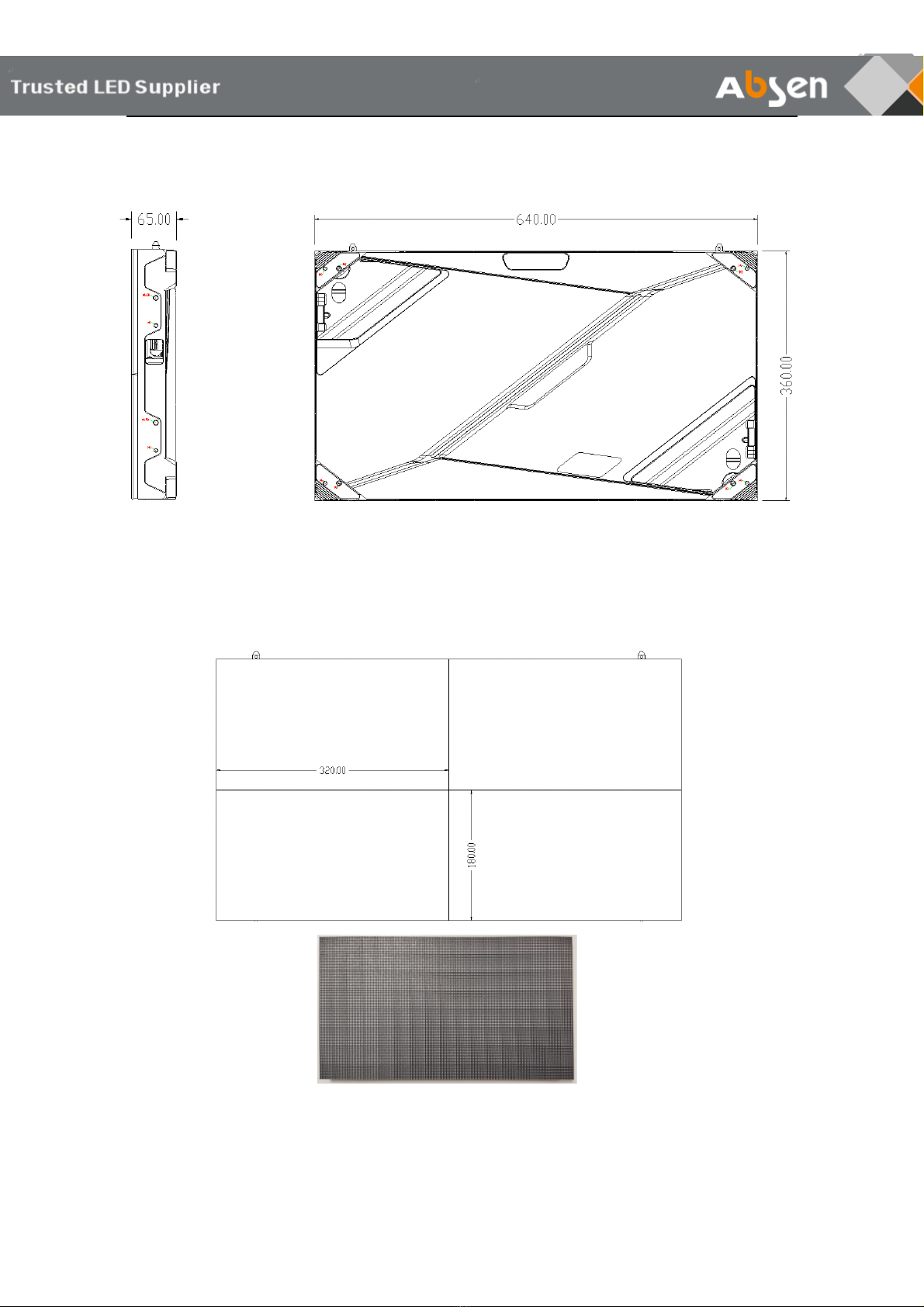
1.3 Panel size .................................................................................................................................................................................. 8
1.4 Module size .............................................................................................................................................................................. 8
2 PRODUCT COMPONENTS ........................................................................................................................................................ 9
2.1 Panel Introduction ................................................................................................................................................................. 9
2.2 Product Accessories ............................................................................................................................................................ 10
3 PREPARATION BEFORE INSTALLATION ............................................................................................................................. 14
3.1 Installation tools ................................................................................................................................................................... 14
3.2 Installation site environmental requirements .............................................................................................................. 15
3.3 Precautions for product installation ............................................................................................................................... 15
4 PRODUCT INSTALLATION ...................................................................................................................................................... 16
4.1 Ground stack installation ................................................................................................................................................... 16
4.2 Wall-mounted installation ................................................................................................................................................ 18
4.3 Rigging installation .............................................................................................................................................................. 20
4.4 Trim pieces installation ....................................................................................................................................................... 21
5 CABLE CONNECTION ............................................................................................................................................................... 23
5.1 LED Panel connection .......................................................................................................................................................... 23
5.2 Power cable connection ..................................................................................................................................................... 24
5.2 Signal cables connection .................................................................................................................................................... 25
5.3 Power cord and signal test ................................................................................................................................................ 26
6 PRODUCT MAINTENANCE ..................................................................................................................................................... 27
6.1 Service tools ........................................................................................................................................................................... 27
6.2 Module maintenance .......................................................................................................................................................... 27
6.3 Receiving card/Hub board/PSU maintenance ............................................................................................................ 28
6.4 Product maintenance precautions .................................................................................................................................. 29
6.5 Troubleshooting ................................................................................................................................................................... 31

3 KL II Series User Manual
Safety information
The following marks on the product and in this manual indicate important safety
measures.
WARNING: Be sure to understand and follow all safety guidelines, safety instructions, warnings and precautions listed in
this manual.
This product is for professionals use only!
This product may result in serious injury or death due to fire hazard, electric shock or on dropping.
Please read this manual carefully before installing, powering up, operating and maintenance of thisproduct.
Follow safety instructions in this manual and on the product. If you have any questions, please seek
help from Absen.
Beware of electric shock!
• To prevent electric shock the device must be properly grounded during installation. Do not ignore
using the grounding plug, or else there is a risk of electric shock.
• During a lightning storm, please disconnect the device’s power supply, or provide other suitable
lightning protection. If the equipment is not in use for a long time, please unplug the power cord.
• When performing any installation or maintenance work (e.g. removing the fuses, etc.,) make sure to
turn off the master switch.
• Disconnect AC power when the product is not in use, or before disassembling, or installing the
product.
• The AC power used in this product must comply with local building and electrical codes, and should
be equipped with overload and ground fault protection.
• The main power switch should be installed at a location near the product and should be clearly
visible and easily reached. This way in case of any failure the power can be promptly disconnected.
• Before using this product check all electrical distribution equipment, cables and all connected

KL II Series User Manual 4
devices, and make sure all meet current requirements.
• Use appropriate power cords. Please select the appropriate power cord according to the required
power and current capacity, and ensure the power cord is not damaged, aged or wet. If any
overheating occurs, replace power cord immediately.
• For any other questions, please consult a professional.
Beware of fire!
• Use a circuit breaker or fuse protection to avoid fire caused by power supply cables overloading.
• To avoid fire caused by power supply cables overloading.
• Do not stick or hang anything on the screen.
• Do not modify the product, do not add or remove parts.
• Do not use the product in case ambient temperature is over 40℃.
Beware of injury!
• Warning: Wear a helmet to avoid injury.
• Ensure any structures used to support, fix and connect the equipment can withstand at least 10
times the weight of all the equipment.
• When stacking products, please hold products firmly to prevent tipping or falling.
• Ensure all components and steel frames are securely installed.
• When installing, repairing, or moving the product, ensure the working area is free of obstacles, and
ensure the working platform is securely and stably fixed.
• In the absence of proper eye protection, please do not look directly at the lit screen from within a 1
meter distance.
• Do not use any optical devices that have converging functions to look at the screen to avoid burning
the eyes.
WARNING: Beware of suspended loads.

5 KL II Series User Manual
LED lamps used in the module are sensitive and can be damaged by ESD (electrostatic discharge).
To prevent damage to LED lamps, do not touch when the device is running or switched off.
WARNING: The manufacturer shall not bear any responsibility for any incorrect, inappropriate,
irresponsible or unsafe system installation.
Product disposal
• Any component that has a recycling bin label can be recycled.
• For more information on collecting, reusing and recycling, please contact the local or regional waste
management unit.
• Please contact us directly for detailed environmental performance information.
Warning: Changes or modifications to this unit not expressly approved by the party
responsible for compliance could void the user's authority to operate the equipment.
NOTE: This equipment has been tested and found to comply with the limits for a Class A digital
device, pursuant to part 15 of the FCC Rules. These limits are designed to provide reasonable
protection against harmful interference when the equipment is operated in a commercial
environment. This equipment generates, uses, and can radiate radio frequency energy and, if not
installed and used in accordance with the instruction manual, may cause harmful interference to
radio communications. Operation of this equipment in a residential area is likely to cause harmful
interference in which case the user will be required to correct the interference at his own expense.

KL II Series User Manual 6
1 PRODUCT INTRODUCTION
The KL II Series led video wall products are specifically designed for the indoor commercial display
applications, the cabinet is designed with a size of 640x360mm and a golden aspect ratio of 16:9, which better
fits the mainstream video display, and it’s super easy to build a 2K/4K/8K led video wall with a N x N cabinet
matrix, at the same time, the product combines many features in one, such as grayscale improvement, color
management, high brightness and high refresh rate, which makes it capable of any complex and variable
commercial display environment.
The product is mainly used in: Brand Chain, Shopping Plaza, Hotel Ballroom, TV Station, Bank, Church,
Theater, Enterprise Lobby, Senior Club, Museum, Transportation Hub, Airport, Station, Meeting Room, etc.
1.1 Main features
l Ready-to-use panel with superior quality
l Fine Adjustment grayscale improvement technology
l Color Precision management technology
l Support HFR+ mode (120Hz high frame rate)
l Ultra-low latency enables real-time image display
l Up to 800nits high brightness and 3840 high refresh rate
l Supports dual receiving cards and dual power supply unit
l Multiple ways of installation, hidden wiring design
l Full front service

7 KL II Series User Manual
1.2 Product specification
Parameters
KL1.2 II
KL1.5 II
KL1.8 II
KL2.5 II
Physical
Parameter
Diode Type
SMD1010
SMD1212
SMD1515
SMD1515
Pixel Pitch (mm)
1.25
1.53
1.86
2.5
Panel Dimensions
(WxHxD)/(mm)
640×360×
65
640×360×65
640×360×
65
640×360×
65
Pixel Per Panel
512×288
416×234
344×192
256×144
Panel Weight (kg)
6
6
6
6
Panel Material
Die-cast
aluminum
Die-cast
aluminum
Die-cast
aluminum
Die-cast
aluminum
Module Dimensions
(WxH)/(mm)
320×180
320×180
320×180
320×180
Optical
Parameter
Brightness (nit)
800
800
800
600
Refresh Rate (Hz)
≥3840
≥3840
≥3840
≥3840
Gray scale (bit)
14
14
14
14
Contrast Ratio
4000:1
4000:1
4000:1
3000:1
Color Temperature
(K)
2500-9500 adjustable
Viewing Angle (H/V)
(°)
140/120
160/140
160/140
160/140
Driving Type
1/32
1/52
1/43
1/32
AC Operating Voltage
(V)
100~240
100~240
100~240
100~240
Power Consumption
(Max./Avg.)(W/m²)
615/205
560/187
520/173
410/137
Application
Parameter
Storage Temperature
﹣40~﹢60 (℃)
Operating
Temperature
﹣10~﹢40 (℃)
Storage Humidity
10﹪~85﹪(RH)
Operating Humidity
10﹪~80﹪(RH)
IP Rating (Front/Rear)
IP40/IP21
LED Lifetime
100000 hours
Maintenance
Full front
Installation
Front / Rear installation. Stack / Wall Mount / Rigging(6m)
Certificate
FCC+ETL+CE+RoHS
Note: Power consumption tolerance: ±15%, according to the actual situation

KL II Series User Manual 8
1.3 Panel size
(Side view and Rear view, Unit: mm)
1.4 Module size
320*180
(front view, Unit: mm)

9 KL II Series User Manual
2 PRODUCT COMPONENTS
2.1 Panel Introduction
NOTE:
ü The upper & lower/side screw holes are used to connect panels, and can also be used to adjust the gap in
between.
ü Please use different screw holes base on the way of installation(front/rear)
integrated floating type socket
上下过线孔
Handle
Installation
screw hole
Side splicing screw hole
Side cable through hole
Z-axis adjusting screw hole
Upper & lower splicing
screw hole
Data cable through hole for
Rear installation
Power cable through hole
for Rear installation
Upper & lower cable
through hole
Built-in power cable for vertical
AC power cascade
Power supply unit
Receiving card
Wall mounting
through hole

KL II Series User Manual 10
S
2.2 Product Accessories
Back Strip (Optional):Wall mounting installation accessories, including double and triple back strip.
Hanging bar (Optional):Rigging installation accessories, including single and double hanging bar.
Double back strip
Triple back strip
Double hanging bar
Single hanging bar

11 KL II Series User Manual
Connecting plate (Default) : Ground stacking installation accessories.
Trim pieces: Video wall edge decoration accessories.
Upper trim
pieces
Left side trim pieces
(from front)
Lower trim pieces
Right side trim pieces
(from front)
Connecting plate
M8*60 screws

KL II Series User Manual 12
*Note:Absen will provide the automatic trim pieces calculator base on your screen panel matrix.
Cables:
Data cables for vertical cascade:
Data cables for horizontal cascade:
Power cables for horizontal cascade:
Power cables for vertical cascade:There’s a built-in vertical power cable inside the panel
Power-In Cable: 10 meters long power cable(The official standard); Others specification(Optional)
Location
Trim pieces specs(9 types)
Left & Right
Double height
Top-left&Bottom-right, Bottom-left&Top-right,
Left&right middle
Triple height
Top-left&Bottom-right, Bottom-left&Top-right,
Left&right middle,left&right full height
Upper & Lower
Single width
Universal single trim piece
Double width
Universal double trim piece

13 KL II Series User Manual
Package:Modules and Cabinets are packaged separately:
Modules(40 modules in 1 carton,4 cartons in 1 pallet)
Cabinet(5 cabinets in 1 carton,4 cartons in 1 pallet)

KL II Series User Manual 14
3 PREPARATION BEFORE INSTALLATION
3.1 Installation tools
Installation
tool list
Tool type
function
picture
knife
Open the box
Front
maintenance
tool
Install& maintain the
LED module
Socket
hexagon
wrench
Install the screws
between the LED
cabinets
spanner
Install bolts
PH2
screwdriver
Maintenance and
disassembly
Module & power
supply &
receiving card
screws
multimeter
Measuring power
cord and
distribution box
Laser level
Measuring
installation position
Spirit level
Check the flatness of
the cabinet
installation
tape measure
Measure the
distance
Hexagon
screwdriver
Install and remove
the hexagon socket
screws

15 KL II Series User Manual
3.2 Installation site environmental requirements
1. Before installing the fine pitch series products, test the on-site temperature and humidity to ensure that
the temperature is within 35°C and the humidity is within 70%RH before installation;
2. When the environment exceeds (35
℃
, 70%RH), the screen body is in high temperature and high
humidity, which will cause the LED lamp beads to be damp, and cause a large number of LED lamp beads
on the screen to be damaged;
3.3 Precautions for product installation
3.3.1 Before installation
1. Determine the power distribution plan: Give a specific power distribution plan based on the actual display
size and arrangement sequence, and determine the specifications and quantity of the power distribution
box, main power cords, and the number of power cords connected to the box. Determine the specifications
of the sending box, video processor, and the number of network cables according to the total pixel points
and arrangement sequence.
2. Precautions for power distribution
①
The wiring is neat, horizontal and vertical, and non-cable wires must be laid with ducts or ducts;
②
Lay the signal wires separately from the power wires to avoid interference;
③
The wiring considers three-phase power balance, and try to have the same number of display boxes for
each phase of electrical load;
④
The wire end of the cable needs to press the wire terminal,
⑤
Encode the thread head, and the overall power distribution diagram should be consistent with the actual
wiring to facilitate subsequent troubleshooting;
⑥
Under the premise of considering the safe current carrying capacity, lay the cables from the distribution
box to the display box according to the actual box arrangement;
⑦
For long-distance wiring, consider line loss voltage to ensure that the voltage at the display screen is
within the allowable range;
3. Steel structure construction: construction in accordance with the requirements of the drawings. The
construction must be coordinated with the pipeline construction, and the person in charge of installation
shall supervise it.
4. Tool preparation: match and prepare the types of tools commonly used for display installation, including
screwdrivers, wrenches, multimeters and other tools.
3.3.2 During installation
1. Installation of distribution box: The installation of distribution box must be firm and reliable. The protective
grounding is reliable.
2. Cabinet installation: equipment handling. Sufficient manpower must be equipped to ensure safety. Pay
attention to handle with care, do not knock and damage the appearance and function of the cabinet. When
installing the display screen, check whether the magnet feet are tightened. The power cord and network
cable must be connected in place and correct, whether the network cable is inserted in place and the
screen connection sequence is correct.
3. Wiring sequence: first connect the box with a box-connecting power cord in series, and then use 3 main
power cord to connect from the distribution box or socket to the bottom box.
4. Power connection: First confirm that the power supply terminal is in the "disconnected" state, and the
self-consumption terminal must be connected (equipment switch or distribution box, etc.). Connect the
power supply terminal only after checking that the connection of the power supply terminal is correct.
Connect the protective ground first, then connect the neutral line, and finally connect the phase line. After
the power supply is connected: Check the power supply terminal switch or the equipment power distribution
voltage, and "cut off" the power supply after confirming that it is correct. The power cord must be
distinguished by color, ground wire, neutral wire and A, B, C and other phase wires.
5. Cabinet adjustment: Check whether the display screen is flat and clean. Fine-tune the gap between the
module and the module, and between the box body and the box body. When installing, make sure that the
box body and the box body must be locked with screws to ensure the left and right/up and down flatness
between the boxes.
6. Power test: Before supplying power to the entire screen and providing control signals, please carefully
check whether the power and signal lines are connected correctly; please carefully check the "L" and "N"
lines on the AC power input port of each cabinet. "PE" line, confirm that there is no short circuit between the
three (measured with a multimeter).
7. Power-on detection: fault judgment, check the appearance. Power-on detection whether there is a bad
screen and whether the text output is correct; if a fault occurs, judge and eliminate the fault based on the

KL II Series User Manual 16
fault phenomenon.
8. Module protection: During the installation of the LED module, the corners of the module should be
protected to avoid collisions causing the lights to fall off. Wear dust-free gloves during installation to avoid
staining the surface of the module with sweat or dust on your hands.
9. Display protection: In the process of installation and construction, a dust collector must be used to reduce
the concentration of dust. After construction, a clean canvas must be used to cover the lamp surface of the
large screen to prevent dust and corrosive gas from attacking the lamp beads.
4 PRODUCT INSTALLATION
Product installation type:
NO.
Installation type
remark
1
Ground stack installation
Install the LED cabinets on the steel structure with the
connecting plate
2
Wall-mounted installation
Use sub frames to install on the wall
3
Rigging installation
Use hanging beams to install on the air frame or truss
4.1 Ground stack installation
KL II series ground stack installation accessories are as follows:
No.
Name
Picture
Function
1
connecting plate
Used to fix the LED cabinet to the
steel structure
2
M8x10mm bolt
Used to fix the LED cabinet to the
steel structure
3
M6x30mm bolt
Connect and fix the cabinets
between top and bottom and left
and right
Front installation:
Step 1:
Take out the KL II cabinet frame from the package
and install the first layer at the bottom
Note: install from the middle to both sides

17 KL II Series User Manual
Step 2:
Install the adjacent cabinets on the left and right
one by one, and fix them with M6x30m bolts
between the left and right sides, and then tighten
them with a socket hexagon wrench;
Note: During the installation process, ensure the
flatness of the splicing of the cabinet structure.
Step 3:
Place the connecting plate behind the square
tube, insert the M8*10mm bolt from the
connecting plate hole and lock it to the installation
hole of the cabinet, and then use a spanner to fix
the bolt tightly.
Note: In the process of tightening the bolts,
confirm the flatness of the structure splicing from
the front.
Step 4:
Install the second layer, fix LED cabinets with
M6x30mm bolts between top and bottom, and
then tighten them with a socket hexagon wrench;
Note: During the installation process, ensure the
flatness of the splicing of the cabinet frames
Step 5:
Follow the above steps to complete the
installation of all cabinet frames
Step 6: Install the cabinet power cord and network
cable and ensure that they are correct, then install
the LED modules
Rear installation:
step 1:
Take out the KL II cabinet frames from
the package and install the first layer at
the bottom.
Install the adjacent frames on the left and
right one by one, and fix them with
M6x30m bolts between the left and right
sides, and then tighten them with a
socket hexagon wrench;

KL II Series User Manual 18
Note: Start the installation from the
middle to the two sides. During the
installation process, ensure the flatness
of the splicing of the cabinet frames.
Step 2:
Place the connecting plate behind the
square tube, insert the M8*10mm bolt
from the connecting plate hole and lock it
to the cabinet installation hole, and then
use a spanner to tighten the bolt.
Note: In the process of tightening the
bolts, make sure that the joints of the
structure are flat.
Step 3:
Install the second layer, fix LED cabinets
with M6x30mm bolts between top and
bottom, and then tighten them with a
socket hexagon wrench;
Note: During the installation process,
ensure the flatness of the splicing of the
cabinet frames
Step 4:
Follow the above steps to complete the
installation of all cabinet frames
Step 5:
Install the cabinet power cord and
network cable and ensure that they are
correct, then install the LED modules
4.2 Wall-mounted installation
The accessories required for the wall-mounted installation of KL II series are as follows:
No.
Name
specification
Picture
function
remark
1
Sub
frames
Length:720mm
(2 in1)
Length:1080mm
(3in1)
Used to
connect fixed
cabinet
combination
Provided

19 KL II Series User Manual
2
bolt
M8x30mm
Used to fix
the cabinet to
the sub frame
Provided
3
Tapping
screws
M10 x 60mm
Fix the
cabinets
combination
to the
wooden wall
Not
Provided
4
Expansio
n screws
M10x60
Fix the
cabinets
combination
to the
concrete wall
Not
Provided
Cabinet installation operation
step 1:
Take out the KL II cabinet frame from the package,
and install the 2 or 3pcs cabinet frames on the sub
frames . Each cabinet frame needs to install 4 M8
bolts on the sub frame.
Note: the M6x10mm bolts and nuts should be used to
connect and fix the upper and lower cabinets to
ensure that the cabinet combination unit is spliced to
the flat screen without dislocation.
Step 2:
Confirm the installation position of the screen on the
wall and make a mark on the wall, take a cabinet
assembly installation unit to the wall and mark the
fixing position of the drilling hole with a marker. Install
self-tapping screws on wooden walls or use
percussion drills to drill holes on cement concrete
walls to install expansion screws.
Note: During the installation process, use a level to
ensure the flatness of the cabinet assembly unit
installation.
Step 3:
Install the adjacent cabinet combination units one by
one, fix them to the wall according to the method in
step two, and tighten the screws between the left and
right cabinets.
Note: When installing between the left and right boxes,
make sure that they are flat before locking and fixing.
Step 4:
Follow the steps above to install the second layer. Use
M6x60m bolts and M6 nuts to fix the cabinets between
the top and bottom.
Note: During the installation process, ensure the
flatness of the splicing of the cabinet structure.

KL II Series User Manual 20
Step Five:
Complete the installation of all cabinet combination
units, and install cables according to the power supply
and signal routing design plan, and install the LED
module after power-on inspection and confirmation.
4.3 Rigging installation
This product can be hoisted by hanging beams
Lifting installation steps:
1.First, use airplane belts or wire ropes to fix the hanging beams on the truss or steel structure,
and use connecting blocks to connect the left and right hanging beams, and keep them on the
same horizontal line.
(Note: When installing the hanging beam, the arrow direction on the top of the hanging beam is
the same as the front of the LED display)
2.Align the positioning pin of the cabinet with the positioning hole of the hanging beam, and use
M6 bolts to lock the cabinet and the hanging beam.
(Note: Two M6 bolts are installed between the hanging beam and the cabinet, one is installed
from the left side of the front, and the other is installed from the left side of the back)
3.According to the above operation method, install the adjacent cabinets of the first layer in turn,
and use M6x30mm bolts to lock.
This manual suits for next models
6
Table of contents
Other Absen Digital Signage manuals