ABW-INNOVATIONS LLC LAHAINA, HI 96761 (256) 648-5172
www.cone-genie.com www.abw-innovations.com
TIMER / SENSOR ADJUSTMENT
Set the Cutoff Distance
The cutoff distance for Q60AF sensors can be adjusted between 200 mm to 2000 millimeters (8 in to 80 in).
To maximize contrast, position the lightest possible background to be used, at the closest position it will come to the sensor during use.
Using a small screwdriver in the adjustment screw, adjust the cutoff distance until the threshold is reached and the green Light Sensed
indicator changes state. If the indicator never turns ON, the background is beyond the maximum sensing cutoff and will be ignored.
Note the position of the rotating cutoff position indicator at this position. Then repeat the procedure, using the darkest target, placed in
its most distant position for sensing. Adjust the cutoff so that the indicator is midway between the two positions.
Target Background
Cutoff
Distance
E
R2
R1
Figure 3. Set the cutoff distance approximately midway between the
farthest target and the closest background
ON
OFF
DELAY
DELAY
DO
SIG
LO
RANGE
I
n
c
r
e
a
s
i
n
g
D
i
s
t
a
n
c
e
Set Cutoff Midway
Between
Farthest Target Object
Closest Background
Figure 4. Setting the cutoff distance
Features and Indicators
Note: Outputs are active during on/off timing selection mode.
ON Delay
Steady Green: Run mode, ON delay is active
Flashing Green: ON Delay Selection mode is active
OFF Delay
Steady Green: Run mode, OFF delay is active
Flashing Green: OFF Delay Selection mode is active
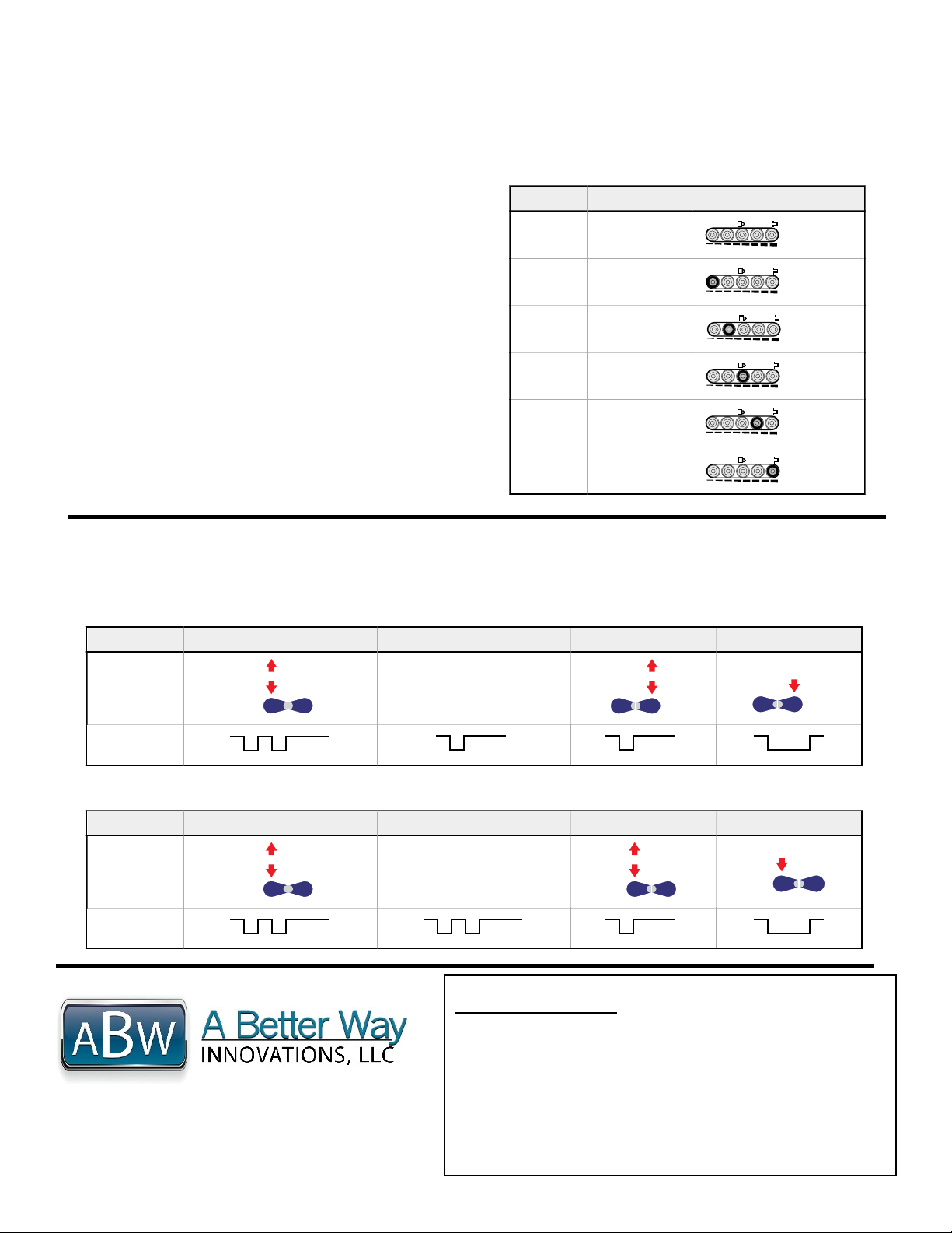
5-Segment Light Bar2
Indicates relative delay time during ON or OFF Delay
Selection modes
Output Indicator
Steady Amber: Outputs are conducting
Steady Green: During ON/OFF Delay Selection modes
Dark Operate Indicator
Steady Green: Dark Operate is selected
Lockout Indicator
Steady Green: Buttons are locked out
Light Operate Indicator
Steady Green: Light Operate is selected
Signal Indicator
Steady Green: Sensor is receiving signal
Flashing Green: Marginal signal (1.0 to 2.25 excess
gain)
ON/OFF Delay Push
Buttons and Indicators
Light Sensed Indicator
Light Operate Selected
Push Button
Lockout Indicator
Dark Operate Selected
Output Conducting
(Bi-color Amber/Green)
The indicators, above right, also function as a 5-
segment light gar during delay selection modes
Cutoff Adjustment Screw