Academy of Model Aeronautics Fokker Eindecker E.III ARF User manual

1
For more cool Wattage products visit our website at http://watt-age.globalhobby.com
The Wattage Fokker Eindecker E.III ARF is distributed exclusively by Global Hobby Distributors 18480 Bandilier Circle, Fountain Valley, CA 92728
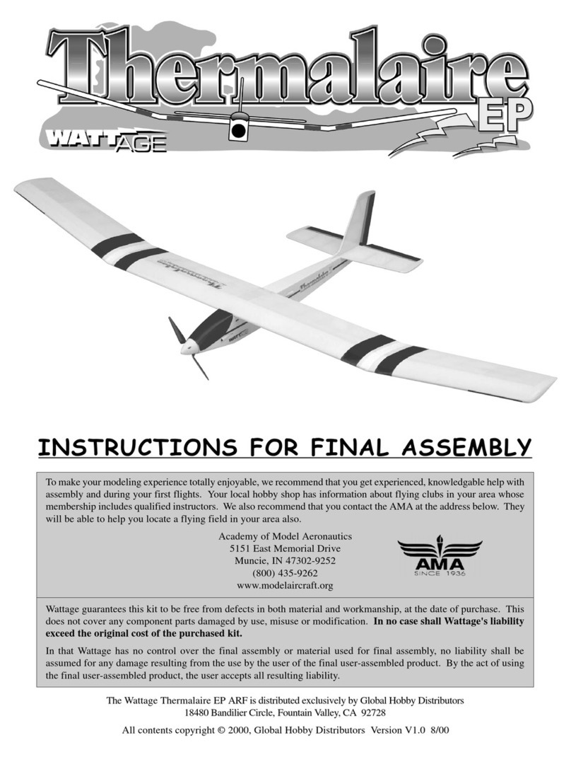
INSTRUCTIONS FOR FINAL ASSEMBLY
FOR YOUR INFORMATION
To make your modeling experience totally enjoyable, we recommend that you get experienced, knowledgeable help with
assembly and during your first flights. Your local hobby shop has information about flying clubs in your area whose
membership includes qualified instructors. If there is no hobby shop in your area, we recommend that you contact the
AMAat the address below. They will be able to help you locate a flying field near you.
Academy of Model Aeronautics
5151 East Memorial Drive
Muncie IN 47302-9252
(800) 435-9262
www.modelaircraft.org
Specifications:
●Wing Area: 340 square inches
●Wing Span: 42.25 inches
●Length: 31.5 inches
●Functions: Rudder, Elevator, Throttle
●Power: 380 Motor w/Gear Box (included)
●Radio: 3 Channel Micro System
All contents copyright © 2001, Global Hobby Distributors Version V1.0 September 2001
Product Part Number 128411

2Need help or have any questions? Call us at 1-714-963-0329 or send us an Email at service@globalhobby.net
ThisR/Cairplaneisnotatoy!Ifmisusedorabused,itcancauseseriousbodilyinjuryand/ordamagetoproperty. Flyonly
inopenareasandpreferablyatadedicatedR/C flying site. Wesuggesthavingaqualifiedinstructorcarefully inspect your
airplane before its first flight. Please carefully read and follow all instructions included with this airplane, your radio
control system and any other components purchased separately.
TABLE OF CONTENTS
SAFETY WARNING
OUR GUARANTEE:
Wattageguarantees this kit tobe freefrom defectsinbothmaterial and workmanship, atthe dateofpurchase. Thisdoes
not cover any component parts damaged by use, misuse or modification. In no case shall Wattage's liability exceed
the original cost of the purchased kit.
In thatWattage has no control over the final assembly or material used for final assembly, no liability shall be assumed
foranydamageresultingfromtheuseby the user of the final user-assembled product. By theact of using the final user-
assembled product, the user accepts all resulting liability.
Safety Warning..........................................................................................................2
Introduction ...............................................................................................................3
Our Recommendations..............................................................................................4
Tools and Supplies Required ....................................................................................4
Kit Contents...............................................................................................................5
Metric Conversion Chart...........................................................................................5
Replacement Parts.....................................................................................................6
A Note About Covering ............................................................................................6
Section 1: Motor Break-In (optional) ...............................................................7
Section 2: Assembling the Wing.......................................................................9
Section 3: Mounting the Wing ........................................................................11
Section 4: Mounting the Horizontal Stabilizer ...............................................12
Section 5: Mounting the Vertical Stabilizer....................................................14
Section 6: Installing the Landing Gear ...........................................................15
Section 7: Hinging the Control Surfaces ........................................................17
Section 8: Installing the Servos ......................................................................19
Section 9: Installing the Pushrods...................................................................20
Section 10: Installing the Propeller & Cowl ..................................................24
Section 11: Installing the Cockpit Deck ........................................................25
Section 12: Final Assembly............................................................................27
Section 13: Balancing.....................................................................................29
Section 14: Control Throws ...........................................................................30
Section 15: Preflight Check & Safety ............................................................30
Section 16: Flying the Fokker Eindecker 400 EP 31
Section 17: Glossary of Terms .......................................................................32
Section 18: Motor Maintenance .....................................................................34
Product Evaluation Sheet........................................................................................35

3
For more cool Wattage products visit our website at http://watt-age.globalhobby.com
Thisinstructionmanualisdesigned to guide you through theentire final assemblyprocess of your newairplane in the
least amount of time possible. Along the way you'll learn how to properly assemble your new airplane and also learn
tips that will help you in the future. We have listed some of our recommendations below. Please read through them
before beginning assembly.
●Please read through each step before beginning as-
sembly. Youshould find thelayoutvery complete and
straight forward. Our goal is to guide you through
assembly without any of the headaches and hassles
that you might expect.
●Thereare check boxes nexttoeach step. After you
completea step, checkoffthe box. Thiswill help pre-
vent you from losing your place.
●Cover your work table with brown paper or a soft
cloth, both to protect the table and to protect the parts.
●Keep a couple of small bowls or jars handy to put
the small parts in after you open the accessory bags.
●We're all excited to get a new airplane in the air, but
take your time. This will ensure you build a straight,
strong and great flying airplane.
●If you come across this symbol ☛, it means that
this is an important point or an assembly hint.
●A glossary of Terms begins on page # 32. Refer to
it if you come across any unfamiliar terms.
If you should find a part missing or damaged, or have any questions about assembly, please
contact us at the address below:
Wattage Customer Service
18480 Bandilier Circle
Fountain Valley CA 92728
Phone: (714) 963-0329 Fax: (714) 964-6236 E-mail: service@globalhobby.net
INTRODUCTION
Thank you for purchasing the new Wattage Fokker Eindecker E.III ARF. Before
completing the final assembly of your new airplane, please carefully read through
this instruction manual in its entirety. Doing so will ensure success the first time
around!
The original Fokker Eindecker was the first monoplane of WWI. It was considered the technological wonder of its day.
Itslight wing loadingand stall resistantwing meant itcould turn insideevery opponent outthere. Not only wasit the first
monoplaneofthewar, it was also thefirst tofeature a synchronizedforward firingmachine gun thatcould fire throughthe
arc of the propeller. With this technology, better aim and precision was possible, giving it an even greater advantage.
Max Immelmann scored his first victory flying the Eindecker. Soon after its debut in 1915, it proved its advantage. The
Eindecker E.I was so potent that Allied opponents called themselves Fokker Fodder. Germans were so protective of its
technology that the airplane was never allowed to fly across into enemy territory to prevent giving the Allied forces this
advanced technology, should the airplane be shot down.
Now you can rule the skies with your Fokker Eindecker 400. Wattage's Eindecker handles well at all throttle settings and
performs tight turns with ease. The low wing loading and lifting airfoil give the Eindecker long flights and great perfor-
mance. The Eindecker is expertly built and covered using standard construction techniques. Only high quality balsa,
plywood and real iron-on covering material is used. Assembly is very quick and easy, owing the prefabricated and
painted parts. Experienced modelers will appreciate the craftsmanship of this fun-flying Fokker.

4Need help or have any questions? Call us at 1-714-963-0329 or send us an Email at service@globalhobby.net
❑Kwik Bond Thin C/A # 887500
❑Kwik Bond Thick C/A # 887510
❑Kwik Bond 5 Minute Epoxy # 887560
❑Kwik Bond C/A Debonder # 887545
❑# 1 Phillips Head Screwdriver
❑7/64" Hex Wrench
❑Magnum Z-Bend Pliers # 237473
❑Wire Cutters
❑Needle Nose Pliers
❑Excel Modeling Knife # 692801
❑Scissors
❑Electric Drill
❑Assorted Drill Bits
❑Ernst Airplane Stand # 223977
❑Ruler
❑Pencil
❑Builder's Triangle
❑220 Grit Sandpaper w/Sanding Block
❑Dubro T-Pins # 567677
❑Masking Tape
❑Scotch®Tape
❑Paper Towels
❑Rubbing Alcohol
❑NHP Epoxy Mixing Sticks # 864204
❑NHP Epoxy Mixing Cups # 864205
❑Emerald Motor Spray # 340186 (optional)
❑Trinity Break-In Drops # 840768 (optional)
❑Rubber Bands (optional)
This section lists the items you will need to purchase for your new Fokker Eindecker. These suggestions are not set in
stone, but they should provide you with a good starting point.
OUR RECOMMENDATIONS
TOOLS AND SUPPLIES REQUIRED
If you already have a radio system:
Hitec 555 Micro Receiver
Hitec RX Crystal
P/N 444227 Cirrus CS-21 Micro Servos (2)
P/N 128484 Wattage IC-15A ESC
P/N 128522 Wattage 8C 600Mah NiCD Flight Battery
P/N 130103 Wattage 1 amp AC/DC Peak Charger
P/N 869020 Dubro Double-Sided Tape
optional P/N 128524 Wattage 8C 800Mah NiMH Flight Battery
If you don't have a radio system:
Hitec Focus 3 AM Radio Control System
P/N 444227 Cirrus CS-21 Micro Servos (2)
P/N 128484 Wattage IC-15A ESC
P/N 128522 Wattage 8C 600Mah NiCD Flight Battery
P/N 130103 Wattage 1amp AC/DC Peak Charger
P/N 869020 Dubro Double-Sided Tape
optional P/N 128524 Wattage 8C 800Mah NiMH Flight Battery
IMPORTANT
When purchasing the Hitec 555 Micro receiver, be sure it is compatible with your transmitter. When purchasing the
crystal, make sure that it is on the same frequency as your transmitter.

5
For more cool Wattage products visit our website at http://watt-age.globalhobby.com
To convert inches into millimeters: Inches x 25.4 = mm
1/64" = .4mm
1/32" = .8mm
1/16" = 1.6mm
3/32" = 2.4mm
1/8" = 3.2mm
5/32" = 4.0mm
3/16" = 4.8mm
1/4" = 6.4mm
3/8" = 9.5mm
1/2" = 12.7mm
5/8" = 15.9mm
3/4" = 19.0mm
1" = 25.4mm
2" = 50.8mm
3" = 76.2mm
6" = 152.4mm
12" = 304.8mm
18" = 457.2mm
21" = 533.4mm
24" = 609.6mm
30" = 762.0mm
36" = 914.4mm
METRIC CONVERSION CHART
We have organized the parts as they come out of the box for easier identification during assembly. Before you begin
assembly, group the parts like we list them below. This will ensure that you have all of the parts before you begin
assembly and it will also help you become familiar with each part. If you find any parts missing or damaged, please
contact us below:
AIRFRAME ASSEMBLIES
❑{1} Fuselage w/Motor & Gear Box
❑{1} Cockpit Deck
❑{1} Right Wing Half
❑{1} Left Wing Half
❑{1} Horizontal Stabilizer w/Elevator
❑{1} Vertical Stabilizer w/Rudder
❑{1} Molded Cowl
PUSHROD ASSEMBLIES
❑{2} 1mm x 445mm Pushrod Wires
❑{2} Plywood Control Horns
KIT CONTENTS
Wattage Customer Service
18480 Bandilier Circle
Fountain Valley CA 92728
Phone: (714) 963-0329 Fax: (714) 964-6236 E-mail: service@globalhobby.net
LANDING GEAR ASSEMBLY
❑{2} Prebent Main Gear Wires
❑{2} Main Gear Wheels
❑{2} Nylon Landing Gear Straps
❑{4} 3mm x 10mm Wood Screws
❑{2} 3mm Nylon Spacers
❑{2} 3mm Wheel Collars w/Set Screws
WING ASSEMBLY
❑{1} 5mm x 55mm Hardwood Dowel
❑{1} Plywood Cockpit Mounting Block
❑{1} 4mm x 20mm Flange-Head Machine Screw
SPINNER ASSEMBLY
❑{1} Molded Spinner
❑{1} Molded Propeller Shaft Adaptor Set
❑{2} 3mm x 10mm Wood Screws
MISCELLANEOUS ITEMS
❑{1} 3mm x 16mm Flange-Head Wood Screw
❑{1} Pilot Figure
❑{1} Machine Gun
❑{1} Propeller
❑{3} Velcro®Squares
❑{1} Decal Set

6Need help or have any questions? Call us at 1-714-963-0329 or send us an Email at service@globalhobby.net
The covering material used on your airplane is real iron-on heat shrink covering material, not cheap "shelf paper."
Because of this, it is possible with heat and humidity changes that the covering on your airplane may wrinkle or sag.
This trait is inherent in all types of heat shrink material. To remove any wrinkles that might be visible you will need to
purchase, or borrow from a fellow modeler, a heat iron. If you need to purchase one, the Global Heat Sealing
Iron # 360900 is recommended.
Follow this simple procedure to remove the wrinkles:
❑Plug in and turn on the sealing iron to the medium-high temperature setting. Allow the iron to heat up for
approximately 5 - 7 minutes.
❑After the iron has reached temperature, lightly apply the iron to the wrinkled section of the covering. Move the iron
slowly over the wrinkled section until the covering tightens and the wrinkles disappear. You will notice that the color of
the covering will darken when it is heated. When the covering cools back down, it will return to its normal color.
☛Ifthe color layer smears fromanyoftheseamsthetemperature of the iron istoohot. Turnthetemperaturedialdown
and wait about 5 minutes for the iron to adjust to the lower temperature. You can remove any excess color streaks using
a paper towel soaked with a small quantity of Acetone.
A NOTE ABOUT COVERING
Wattage stocks a complete line of replacement parts for your Fokker EindeckerARF. Listed below are the replacement
parts that are available along with their respective part numbers for easy ordering convenience. These replacement
parts can be ordered through your local hobby dealer or directly from Wattage by calling 1-714-963-0329.
REPLACEMENT PARTS
WARNING
We do not suggest storing your airplane in an extremely hot environment (like the back of your car in
direct sunlight) for any length of time. The extreme heat could cause the covering material to wrinkle
and possibly damage the fragile components of the radio system, ESC or batteries.
Wing Set - 145200
Gear Box Assembly - No Motor - 145201
Fuselage w/Cockpit Deck - 145202
Cockpit Deck Only - 145203
Stabilizer Set w/Control Horns - 145204
Cowling - 145205
Pilot & Gun - 145206
1-1/2" Plastic Spinner - 145207
Landing Gear Assembly - 145208
Main Gear Wheels - 145209
Hardware Set - 145210
Instruction Manual - 145211
Decal Set - 145212
380 Size Motor - 131340
8 x 6.25 Propeller - 131342

7
For more cool Wattage products visit our website at http://watt-age.globalhobby.com
❑# 1 Phillips Head Screwdriver
❑Needle Nose Pliers
❑Paper Towels
SECTION 1: MOTOR BREAK-IN (OPTIONAL)
YOU'LL NEED THE FOLLOWING SUPPLIES:
❑Trinity Break-In Drops
❑Emerald Motor Spray
❑Rubber Bands
Step 1: Removing the Motor Assembly
❑Using a # 1 phillips screwdriver, remove the two screws
holding the motor assembly in place.
❑Carefully pull the motor assembly from the fuselage.
❑Set the motor assembly, flight battery, charger, radio system and ESC onto your workbench.
❑Charge the flight battery using your peak charger, following the instructions that were provided with the charger.
Also, make sure that the batteries in your transmitter are fully charged.
Step 2: Breaking In the Motor
❑Set the motor assembly between the handles of a pair of
needle nose pliers and secure the motor to the handles using
three rubber bands. This will keep the motor secure enough
for the break-in procedure.
A NOTE TO THE MODELER:
Motor break-in is not absolutely necessary, but taking some time to break in the motor will result in increased motor
performance and longevity. Motor break-in also gives you a chance to test your radio system, ESC and flight battery
before installing them into the airplane.

8Need help or have any questions? Call us at 1-714-963-0329 or send us an Email at service@globalhobby.net
❑Plugtheservo leads and the ESC lead into their proper slots in the receiver. Plugtheredmotorleadintothered motor
lead on the ESC and plug the black motor lead into the black motor lead on the ESC.
IMPORTANT
The leads that are soldered onto the motor are Bullet Connectors. If your ESC does not use Bullet Connectors, you will
need to change the connectors on the motor at this time.
Remember though that you may experience current loss through any style of connector. If you would like to minimize
current loss, we suggest removing the Bullet Connectors and soldering the leads together without the connectors. If you
decide to do this, make sure to cover the exposed solder joints with heat shrink tubing or electrical tape.
❑Turn on the transmitter and plug the flight battery into the ESC. If the motor turns on immediately, use the throttle
stick to turn off the motor.
❑With the motor turned off, test the operation of the servos. Each should move when you move the control stick.
❑Carefully spray a couple of light sprays of Performance
PlusMotorSprayinsidethemotoropeningsandapplyasmall
drop of Trinity Break-In Drops onto each of the two motor
bushings and onto the two gear box bushings.
❑Using a couple of paper towels, wipe off the excess motor spray.
❑Slowlyturn on themotorusing the transmitterthrottlecontrol stick. Position thestickto about 1/3throttleand let the
motor run. While the motor is running, apply a light spray of motor spray inside the motor openings once every minute,
followed by a small drop of Break-In Drops on each of the motor and gear box bushings. Continue to do this until the
battery is fully discharged (i.e., the motor stops).
❑After the battery has discharged and the motor has stopped, spray motor spray through the motor openings until the
fluid runs clear. Apply a couple of drops of Break-In Drops to the motor and gear box bushings and wipe away all of the
excess using paper towels.
❑Reinstall the motor assembly. Reverse the removal procedure for installation.

9
For more cool Wattage products visit our website at http://watt-age.globalhobby.com
❑Kwik Bond 5 Minute Epoxy
❑Excel Modeling Knife
❑Masking Tape
❑Paper Towels
YOU'LL NEED THE FOLLOWING PARTS:
❑{1} Right Wing Half
❑{1} Left Wing Half
SECTION 2: ASSEMBLING THE WING
❑{1} 5mm x 55mm Hardwood Dowel
YOU'LL NEED THE FOLLOWING SUPPLIES:
❑Rubbing Alcohol
❑NHP Epoxy Mixing Sticks
❑NHP Epoxy Mixing Cups
Step 1: Installing the Hardwood Dowel
❑Using a modeling knife, cut away and remove the
excess covering material that overlaps onto the root ribs
of each wing panel.
❑After removing the covering, the root ribs should look
like this.
IMPORTANT
Glue does not stick well to covering material. For the stron-
gest joint, it's important to remove as much covering from
the gluing surfaces as possible.

10 Need help or have any questions? Call us at 1-714-963-0329 or send us an Email at service@globalhobby.net
❑Mix a small quantity of 5 minute epoxy and apply a thin
layer to only one half of the hardwood dowel.
❑Slide the dowel into the hole in one wing half until it
bottoms-out. Removeany excessepoxy before itdries using
apapertowel and rubbing alcohol, and allow the epoxy to set
up before proceeding.
❑After the epoxy has set up, apply strips of masking tape
to the edges of the root ribs. Apply the tape to the top and
bottom of each wing half.
☛The masking tape will prevent excess epoxy from getting
onto the wing when you join the two halves.
Step 2: Joining the Wing Halves
❑Carefully slide the two wing halves together to check
the fit. When pushed firmly together, there should be few or
no gaps between the two.
☛Sothewinghalvesare nottwisted,it'simportanttomake
surethe leadingandtrailingedgesof bothhalveslineupwith
each other.
❑Mix a generous amount of 5 minute epoxy. Apply a thin layer of epoxy to the exposed half of the hardwood dowel
and to the entire surface of both root ribs.Make sure to use enough epoxy to fill any gaps.
☛Be careful not to get any epoxy into the wing-bolt hole in the trailing edge of the wing.
❑Slide the two wing halves together and realign them. Wipe away any excess epoxy using a paper towel and rubbing
alcohol, and hold the wing halves in place until the epoxy sets up.
❑After the epoxy has fully cured, remove the masking tape and double-check the center section joint. If any gaps are
present, mix a small amount of 5 minute epoxy and carefully fill any remaining gaps. Remove any excess epoxy using a
paper towel and rubbing alcohol, and allow the epoxy to thoroughly cure.

11
For more cool Wattage products visit our website at http://watt-age.globalhobby.com
❑Kwik Bond Thin C/A
YOU'LL NEED THE FOLLOWING PARTS:
❑{1} Fuselage w/Motor & Gear Box
SECTION 3: MOUNTING THE WING
❑{1} 4mm x 20mm Flange-Head Machine Screw
YOU'LL NEED THE FOLLOWING SUPPLIES:
❑# 1 Phillips Head Screwdriver
Step 1: Mounting the Wing
❑Carefully apply a couple of drops of thin C/A into the
threaded wing hold-down hole in the fuselage.
☛The C/A will strengthen the threads.
WARNING
Allow the C/A to thoroughly cure before mounting the wing.
❑Secure the wing into place using one 4mm x 20mm
flange-head machine screw.
☛Don't overtighten the screw. You don't want to crush the
wing.
❑Set the wing into the wing saddle and align it. The plywood tab in the leading edge of the wing should fully engage
the forward bulkhead and the predrilled hole in the back of the wing should line up with the hole in the wing hold-down
block.
IMPORTANT
Leave the wing installed for now. You'll use the wing to help you align the horizontal stabilizer in the next section.

12 Need help or have any questions? Call us at 1-714-963-0329 or send us an Email at service@globalhobby.net
❑Kwik Bond 5 Minute Epoxy
❑Ruler
❑Pencil
❑220 Grit Sandpaper w/Sanding Block
❑Masking Tape
YOU'LL NEED THE FOLLOWING PARTS:
❑{1} Horizontal Stabilizer w/Elevator
SECTION 4: MOUNTING THE HORIZONTAL STABILIZER
YOU'LL NEED THE FOLLOWING SUPPLIES:
❑Dubro T-Pins
❑Paper Towels
❑Rubbing Alcohol
❑NHP Epoxy Mixing Sticks
❑NHP Epoxy Mixing Cups
Step 1: Aligning the Horizontal Stabilizer
❑Remove the elevator and hinges from the stabilizer and
set them aside.
❑Using a pencil, draw two centerline marks on top of the
stabilizer,one attheleadingedgeandoneatthetrailing edge.
☛Thebottomofthestabilizerhasthecovering removed to
match the mounting platform on the fuselage.
❑Set the stabilizer onto the fuselage.
❑Line up the two centerline marks on the stabilizer with
the center of the fuselage.
❑Hold the stabilizer temporarily in place using a couple
of pins.
IMPORTANT
The stabilizer should be pushed forward completely. The back of the fuselage will overhang the stabilizer about 1/16".
This is to give relief to the elevator joiner wire.

13
For more cool Wattage products visit our website at http://watt-age.globalhobby.com
❑Using a ruler, measure the distance between the tips of
the stabilizer and the tips of the wing.
☛If the measurements aren't equal, remove the forward
pin (leave the rear pin in place) and pivot the front of the
stabilizer until both measurements are equal.
❑When you are satisfied that the stabilizer is aligned, use a pencil to draw a couple of marks on each side of the
stabilizer where it and the fuselage sides meet, then use a couple of pins to hold the stabilizer firmly in place.
B=B-1
❑With the stabilizer held firmly in place, look from the
frontoftheairplaneat boththewing andthestabilizer. When
aligned properly, the stabilizer should be parallel with the
wing.
IMPORTANT
If the stabilizer is out of alignment, remove it and use 220 grit sandpaper with a sanding block to sand down the higher side
of the stabilizer mounting platform, then reinstall the stabilizer and check the alignment once more. Repeat this procedure
until you are satisfied with the alignment.
C=C-1
Step 2: Mounting the Horizontal Stabilizer
❑Apply a generous amount of 5 minute epoxy to only the top of the stabilizer mounting platform.
❑Set the stabilizer into place and realign it, double
checking all of your measurements once more before the
epoxy sets up. Remove any excess epoxy before it cures
and hold the stabilizer in place until the epoxy sets up.

14 Need help or have any questions? Call us at 1-714-963-0329 or send us an Email at service@globalhobby.net
❑Kwik Bond 5 Minute Epoxy
❑Excel Modeling Knife
❑Ruler
❑Pencil
❑220 Grit Sandpaper w/Sanding Block
❑Builder's Triangle
YOU'LL NEED THE FOLLOWING PARTS:
❑{1} Vertical Stabilizer w/Rudder
SECTION 5: MOUNTING THE VERTICAL STABILIZER
YOU'LL NEED THE FOLLOWING SUPPLIES:
❑Masking Tape
❑Paper Towels
❑Rubbing Alcohol
❑NHP Epoxy Mixing Sticks
❑NHP Epoxy Mixing Cups
Step 1: Aligning the Vertical Stabilizer
❑Remove the rudder and hinges from the stabilizer and
set them aside.
❑Setthevertical stabilizer into place. To alignitproperly,
the rear edge of the stabilizer should be even with the rear
edgeofthefuselage andthestabilizershouldbepusheddown
firmly.
☛Lining up the trailing edge of the vertical stabilizer
with the back of the fuselage will prevent the rudder from
interfering with the elevator joiner wire.
❑While holding the stabilizer in place, use a pencil to
outline the stabilizer onto the top of the fuselage.
❑Using a builder's triangle, check to make sure that the
vertical stabilizer is aligned 90º to the horizontal stabilizer.

15
For more cool Wattage products visit our website at http://watt-age.globalhobby.com
❑Using a modeling knife, cut away the covering material
from within the outline. Remove the covering from the bot-
tom, front portion of the vertical stabilizer, too.
IMPORTANT
Removing the covering will result in a stronger bond for the
glue.
Step 2: Mounting the Vertical Stabilizer
❑Apply a generous amount of 5 minute epoxy to the gluing surfaces of the stabilizer and to the inside of the stabilizer
mounting slot.
❑Setthe stabilizerinto place andrealign it, doublechecking all of your measurementsonce more beforethe epoxy sets
up. Quickly remove the excess epoxy and hold the stabilizer in place until the epoxy has set up.
❑# 1 Phillips Head Screwdriver
❑Excel Modeling Knife
❑Electric Drill
❑1/16" Drill Bit
YOU'LL NEED THE FOLLOWING PARTS:
❑{2} Prebent Main Gear Wires
❑{2} Main Gear Wheels
❑{2} Nylon Landing Gear Straps
SECTION 6: INSTALLING THE LANDING GEAR
❑{4} 3mm x 10mm Wood Screws
❑{2} 3mm Nylon Spacers
❑{2} 3mm Wheel Collars w/Set Screws
YOU'LL NEED THE FOLLOWING SUPPLIES:
❑Ernst Airplane Stand
❑Ruler
❑Pencil
❑Using a modeling knife, cut away the covering material
from over the landing gear slot in the bottom of the fuselage.
The slot is 3/16" wide, 2-3/4" long and 3/8" behind the hatch
cover.
Step 1: Installing the Landing Gear Wires

16 Need help or have any questions? Call us at 1-714-963-0329 or send us an Email at service@globalhobby.net
❑Line up the 90º bend in each landing gear wire with the
predrilled holes in the landing gear block.
❑Firmly push the landing gear into the holes. When
alignedproperlythe wires should be flushwiththebottom of
the fuselage.
❑Thewiresare held in place usingtwo nylonlanding gear
straps. Position the straps equal distances from the end of
each wire.
❑Useapenciltomarkthelocationsofthemountingscrews.
☛Make sure the straps do not hang over the edge of the
hatch cover.
❑Remove the straps and drill 1/16" pilot holes into the fuselage at the locations you marked.
❑Install the straps using four 3mm x 10mm wood screws.
Tightenthescrewscompletelytosecurethelandinggearwires
into place.
Step 2: Installing the Wheels
❑Slide one 3mm nylon spacer onto each axle.
❑Slide one wheel onto each axle.
❑Secure each wheel in place using one 3mm wheel collar
and set screw. Tighten the screws firmly.

17
For more cool Wattage products visit our website at http://watt-age.globalhobby.com
❑Kwik Bond Thin C/A
❑Kwik Bond Thick C/A
❑Kwik Bond C/A Debonder
YOU'LL NEED THE FOLLOWING PARTS:
❑{2} Plywood Control Horns
SECTION 7: HINGING THE CONTROL SURFACES
YOU'LL NEED THE FOLLOWING SUPPLIES:
❑Excel Modeling Knife
❑Ernst Airplane Stand
❑Paper Towels
Step 1: Installing the Control Horns
❑Using a modeling knife, carefully remove the covering
from over the control horn mounting slot in the elevator.
☛Thecovering hasbeen"slit"at thefactory. Youjustneed
to remove the excess.
WARNING
Be careful not to cut through the covering on the opposite
side.
IMPORTANT
Before gluing the control horn into place, you will need to
cut a notch in the front of the control horn to clear the
elevator joiner wire.
❑Apply a bead of thick C/A into the mounting slot.
❑Push the control horn down into the slot and hold it in
place until the glue dries.
❑Repeat the previous procedures to install the rudder control horn.

18 Need help or have any questions? Call us at 1-714-963-0329 or send us an Email at service@globalhobby.net
Step 2: Hinging the Elevator
❑Slide one hinge into each hinge slot in the elevator.
❑Center each hinge within its slot and double check to
make sure the centerline of the hinges is flush with the
leading edge of the elevator.
❑Glueeachhingeintoplaceusing5-6dropsofKwikBond
Thin C/A. Allow a few seconds between drops for the C/A
to "wick" into the hinges, then turn the elevator over and
apply 5-6 drops on the other side of each hinge. Let the
C/A dry for about 10 minutes before proceeding.
☛If any C/Agets on the elevator, it can be removed promptly using a paper towel soaked with a small quantity of Kwik
Bond C/A Debonder.
❑Slidethe elevator anditshinges into thehinge slots inthetrailing edge ofthestabilizer. Adjustthe elevator sothat its
tips are even with the tips of the stabilizer.
❑While holding the elevator tight against the stabilizer,
pivot the elevator down about 45º and apply 5-6 drops of
thin C/A to the exposed area of each hinge. Turn the fuse-
lage over and repeat for the other side of the hinges.
☛Removeany C/A that mayrundownthehingelineusing
C/A Debonder.
❑After the C/A has dried completely - about 15 minutes -
pivot the elevator up and down to free up the hinges.
IMPORTANT
Afterthe C/A hasfully cured, gently graspthe elevator andpullon it likeyou are trying topull out thehinges. Thehinges
should hold securely. If one or more hinges feels loose, apply more C/A to the hinge(s) and allow it to completely cure.
Step 3: Hinging the Rudder
❑Hinge the rudder using the same methods as for the elevator.
IMPORTANT
Make sure that the counter-balance on top of the rudder does not interfere with the leading edge of the vertical stabilizer.

19
For more cool Wattage products visit our website at http://watt-age.globalhobby.com
❑# 1 Phillips Head Screwdriver
❑Electric Drill
SECTION 8: INSTALLING THE SERVOS
YOU'LL NEED THE FOLLOWING SUPPLIES:
❑1/16" Drill Bit
❑Ernst Airplane Stand
Step 1: Installing the Servos
❑Install the rubber grommets and brass collets onto your
elevator and rudder servos. Make sure to install the collets
with the flanges toward the bottom of the servos.
❑Set the servos into the servo tray taking note of their
locations and the positions of the servo output shafts.
☛Thesidesoftheservosshouldbepushedagainsttheedges
of the tray.
IMPORTANT
Run the servo leads out toward the front of the airplane.
❑While holding the servos in place, drill 1/16" pilot holes
through the servo tray for the mounting screws.
❑Install the servos using the wood screws provided with
your radio system.

20 Need help or have any questions? Call us at 1-714-963-0329 or send us an Email at service@globalhobby.net
Step 1: Installing the Elevator Pushrod
❑# 1 Phillips Head Screwdriver
❑Magnum Z-Bend Pliers
❑Wire Cutters
❑Needle Nose Pliers
❑Excel Modeling Knife
YOU'LL NEED THE FOLLOWING PARTS:
❑{2} 1mm x 445mm Pushrod Wires
SECTION 9: INSTALLING THE PUSHRODS
YOU'LL NEED THE FOLLOWING SUPPLIES:
❑Ernst Airplane Stand
❑Ruler
❑Pencil
❑Masking Tape
❑UsingapairofZ-Bendpliers,makeaZ-Bendin one end
of one pushrod wire.
❑Using a modeling knife, remove all but one arm from a small "4-point" servo horn. The remaining arm should
have at least four holes in it.
❑Using a modeling knife, remove the covering material from over the elevator pushrod exit hole. The hole is on the
right side of the fuselage, 2" in front of the rudder hinge line and 1/2" below the stabilizer.
❑Insert the Z-Bend into the third hole out from the center
of the arm.
☛Make sure the longer portion of the pushrod wire is
toward the top of the servo arm.
Table of contents
Other Academy of Model Aeronautics Toy manuals
Popular Toy manuals by other brands

ZONE KIZ
ZONE KIZ 331-040V00 Assembly instruction

The Land of Nod
The Land of Nod Street Vendor Cart Assembly instructions

Art-Tech
Art-Tech F-14 "TOMCAT" JET instruction manual

LEGO
LEGO Ninjago 9440 instructions

Fisher-Price
Fisher-Price Learning Piggy Bank J2462 quick start guide

Faller
Faller 131357 manual

Fisher-Price
Fisher-Price K8845 instruction sheet

Dynacraft
Dynacraft BMW S1000 RR E-TRIKE 6V owner's manual

Hacker
Hacker Calidus 50E user manual

Vex Robotics
Vex Robotics IQ Standard Drive Base Build instructions

XJ-HOME
XJ-HOME XJ-HOME-04 user guide

badger toys
badger toys Badger Basket 15301 Assembly and use instructions