Academy of Model Aeronautics Wattage Thermalaire EP User manual

1
INSTRUCTIONS FOR FINAL ASSEMBLY
The Wattage Thermalaire EP ARF is distributed exclusively by Global Hobby Distributors
18480 Bandilier Circle, Fountain Valley, CA 92728
All contents copyright © 2000, Global Hobby Distributors Version V1.0 8/00
Wattage guarantees this kit to be free from defects in both material and workmanship, at the date of purchase. This
does not cover any component parts damaged by use, misuse or modification. In no case shall Wattage's liability
exceed the original cost of the purchased kit.
In that Wattage has no control over the final assembly or material used for final assembly, no liability shall be
assumed for any damage resulting from the use by the user of the final user-assembled product. By the act of using
the final user-assembled product, the user accepts all resulting liability.
To make your modeling experience totally enjoyable, we recommend that you get experienced, knowledgable help with
assembly and during your first flights. Your local hobby shop has information about flying clubs in your area whose
membership includes qualified instructors. We also recommend that you contact the AMA at the address below. They
will be able to help you locate a flying field in your area also.
Academy of Model Aeronautics
5151 East Memorial Drive
Muncie, IN 47302-9252
(800) 435-9262
www.modelaircraft.org

2
TABLE OF CONTENTS
SAFETY WARNING
This R/C airplane is not a toy! If misused, it can cause serious bodily injury and/or damage to property. Fly only
in open areas and preferably at a dedicated R/C flying site. We suggest having a qualified instructor carefully
inspect your airplane before its first flight. Please carefully read and follow all instructions included with this
airplane, your radio control system and electronic speed control.
Balancing ..............................................................18
Balancing the Thermalaire EP .......................18
Control Throws.....................................................18
Preflight Check.....................................................19
Safety ....................................................................19
ABC's of Flying....................................................20
Basics of Flight.....................................................20
Flying the Thermalaire EP.............................21
Things to Avoid..............................................22
Planning the first Flight .................................22
Basics of Thermal Flying .....................................22
Glossary of Terms.................................................23
Motor Maintenance ..............................................25
Notes.....................................................................25
Product Evaluation Sheet .....................................27
Safety Warning .......................................................2
Introduction ............................................................3
Our Recommendations ...........................................4
Additional Items Required .....................................5
Tools and Supplies Required ..................................5
Kit Contents............................................................6
Full Size Hardware Drawings ................................7
Motor Break-In.......................................................7
Breaking In the Motor......................................7
A Note About Covering .........................................8
Wing Assembly ......................................................9
Joining the Wing Panels...................................9
Wing Installation ..................................................10
Installing the Wing Bolts ...............................10
Tail Group Installation..........................................11
Aligning the Horizontal Stabilizer.................11
Mounting the Stabilizers................................11
Installing the Rudder Pushrod .......................12
Servo Installation..................................................13
Aligning the Servos .......................................13
Mounting the Servos ......................................13
Servo Horn Installation ........................................13
Installing the Elevator Servo Connector........13
Installing the Servo Horn...............................14
Adjusting the Elevator Pushrod .....................14
Installing the Rudder Servo Connector..........15
Installing the Servo Horn...............................15
Adjusting the Rudder Pushrod.......................15
Final Assembly.....................................................16
Installing the Receiver ...................................16
Installing the ESC ..........................................17
Installing the Flight Battery ...........................17
Installing the Hatch Cover .............................18

3
INTRODUCTION
Thank you for choosing the Wattage Thermalaire EP ARF and welcome to the exciting world of electric
powered gliders! Whether you have built and flown other electric airplanes in the past, or if this is your first, you
will appreciate the high quality, ease of assembly and excellent flight characteristics of the Thermalaire EP ARF.
The Thermalaire EP ARF is a 1.8 meter electric powered glider utilizing all balsa and light-ply built up
construction techniques. The polyhedral wing design is uses a flat bottom that stays incredibly stable through-
out the entire flight envelope and also produces good lift. The center wing panel is built using true D-Tube
construction with balsa sheeting and shear webbing for great strength. The outer tip panels are built light to
keep the overall weight to a minimum. The fuselage is built using balsa and light-ply and the empennage is built
using lightweight balsa. This adds up to an airplane that is light, climbs out with authority and also thermals
very well.
When you open the box, you will notice that you won't have much left to do or to purchase to finish your
new airplane. Included is a direct drive motor with the folding propeller assembly and motor wiring preinstalled.
The airframe is completely built and covered by master craftsmen, who take their time to ensure that every part
is straight and properly glued. But what really sets the Wattage Thermalaire EP apart from other electric gliders
in its price range is the amount of assembly that has been done for you. The Thermalaire EP does not require
any glue to assemble. The wing is held together using steel pins, then is bolted to the fuselage. The horizontal
and vertical stabilizers bolt in place and the control horns are already installed for you. Even the motor, folding
propeller assembly and canopy have been preinstalled for you.
We hope you enjoy your new Wattage Thermalaire EP ARF as much as we have enjoyed designing and
building it for you. If you have any questions or comments, please feel free to contact us. We have also
included a product survey in the back of this manual. Please take the time to fill it out and send it to us. We
would enjoy hearing any comments or suggestions you may have.
This instruction manual is designed to guide you through the entire final assembly process of your new
Wattage Thermalaire EP ARF in the least amount of time possible. Along the way you'll learn how to
properly assemble your new airplane and also learn many tips that will help you in the future. We have
listed some of our recommendations below. Please read through them before going any further.
✔Please read through each step before starting
assembly. You should find the layout very com-
plete and simple. Our goal is to guide you through
assembly without any of the headaches and hassles
you might expect.
✔There are check boxes next to each step. After
you complete a step, check off the box. This will
help you keep from losing your place.
✔Cover your work table with brown paper or a
soft cloth, both to protect the table and to protect
the individual parts.
✔Keep a couple of small bowls or jars handy to
put the small parts in after you open the accessory
bags.
✔We have included a glossary of terms begin-
ning on page # 23 . Check it out if you come across
a term that is unfamiliar to you.
✔We're all excited to get a new airplane in the
air, but take your time. This will ensure you build
a straight, strong and great flying airplane.
✔If you come across this symbol ☛, it means
that this is an important point or an assembly hint.
If you should find a part missing or damaged, or have any questions about assembly, please contact us at the
address below:
Wattage Customer Care
18480 Bandilier Circle
Fountain Valley, CA 92728
Phone: (714) 963-0329 Fax: (714) 964-6236 E-mail: service@globalhobby.net

4
The following section describes our recommendations to help you in deciding which types of accessories to
purchase for your new Wattage Thermalaire EP ARF. We have tested all of these items with the airplane and
found that these products will offer the best in performance, reliability and economy.
RADIO SYSTEM
MOTOR CONTROLLER
OUR RECOMMENDATIONS
Focus 3 AM
P/N 128471
To operate the motor, we highly suggest using a propor-
tional electronic speed control (ESC) that features
battery eliminator circuitry (BEC) and auto-cutoff. BEC
allows you to eliminate the receiver battery and uses the
flight battery to control both the motor and the radio
system. Eliminating the receiver battery provides a great
weight savings which effectively increases performance.
Theauto-cutoff feature turnsoffthe motorwhen thevolt-
age in the battery drops too low to operate the radio
system safely. This guarantees safe operation throughout the entire flight. To obtain these features, we suggest
using the Wattage IC-380 30A ESC. If you decide not to use a proportional electronic speed control, an elec-
tronic switch like the Hitec Motor Controller SP-1003 (part # 759850) is an economical way to turn the motor
on and off. This switch does not offer any proportional speed, only off or full power.
The Thermalaire EP ARF will require a minimum 3
channel radio control system that includes two stan-
dard servos. The radio system we recommend is the
Hitec Focus 3 AM radio. This radio system includes
two standard servos, receiver, servo mounting hardware
and a setup guide. If you already own a radio system,
or want to purchase a radio system that will be more
upgradeable in the future, a four or more channel radio
with two standard servos will work fine. If you decide
to go this way, our recommendation would be to use
the Hitec Flash 4X FM Computer radio. This is a very good radio system that offers the capability to grow as
your experience grows. A standard size receiver will fit in the Thermalaire EP, so the purchase of an after-
market micro or mini receiver is not necessary.
FLIGHT BATTERY
Thebattery youchoose shouldbe a7 cell(8.4Volt) Nickel
Cadmium battery pack. Choose a battery pack between
1100Mah and2000Mah. A premadeR/C carbattery such
as the Trinity 1400Mah flat pack works very well. A 6
cell battery pack will fly the Thermalaire EP; however,
climb out will be slower than if you use a 7 cell pack.
Today's new generation of Sub-C 3000Mah Nickel Metal
Hydride batteries also performs well, but requires a linear charger featuring adjustable peak cutoff voltage.
P/N 842010

5
P/N 350360
Because the flight battery powers both the motor and
the radio system, we suggest using an Automatic Delta
Peak Charger such as the Promax Black Widow Peak
Charger or the Promax Activator Digital Peak Charger
(part # 885650). It is vital to the Thermal-Air EP's fly-
ing performance that the battery pack be fully charged
every flight, so using a peak charger is very important.
ADDITIONAL ITEMS REQUIRED
❑{1}Hitec Focus 3 AM Radio System
❑{1}Trinity AA Batteries - 8 pack # 837801
❑{1}Wattage IC-380 30A ESC # 128471
❑{1}Trinity 7C 1400Mah Battery # 842010
❑{1}Promax Black Widow Charger # 350360
TOOLS AND SUPPLIES REQUIRED
❑Pacer Thread-Lock # 339162
❑# 1 Phillips Head Screwdriver
❑# 2 Phillips Head Screwdriver
❑Small Flat Blade Screwdriver
❑Large Flat Blade Screwdriver
❑Excel Modeling Knife # 692801
❑Adjustable Wrench
❑Needle Nose Pliers
❑Wire Cutters
1
2
3
4
5
6
7
RECOMMENDED ITEMS
OPTIONAL ITEMS
❑{1}Hitec Flash 4X FM Computer Radio System
❑{1}Trinity 7C 1700Mah Battery # 841283
❑{1} PromaxActivatorDigitalPeakCharger#885650
❑Electric or Hand Drill
❑1/16” Drill Bit
❑5/64” Drill Bit
❑12” Straight Edge Ruler
❑Pen or Pencil
❑Masking Tape
❑Trinity Break-In Drops # 840365
❑Performance Plus Motor Spray # 340186
❑Paper Towels - not pictured
10
11
12
13
14
15
16
8
BATTERY CHARGER
9
17
1
2
3
4
5
1
3
4
5
18
2
1
2
3
4
5
6
7
8
9
10
11
12
13
14
15
16
17

6
We have organized the parts as they come out of the box for easier identification during assembly. Each photo
below represents the parts that are required in a main section of the assembly process. Before you begin
assembly, group the parts like we show. This will ensure that you have all of the parts before you begin
assembly and it will also help you become familiar with each part. The corresponding part number is listed first,
then the quantity of that particular part, along with a short description of the part. As you proceed through
assembly, you will notice the same part number listed next to a particular part necessary for that step. If you
have any questions as to what that part might be, refer back to this section.
❑{1} Fuselage w/Motor and Propeller Assembly
❑{1} Center Wing Panel
❑{1} Right Wing Panel
❑{1} Left Wing Panel
❑{1} Horizontal Stabilizer w/Elevator
❑{1} Vertical Stabilizer w/Rudder
1
2
3
4
5
❑{2} 3mm x 60mm Steel Pins
❑{2} 3mm x 20mm Steel Pins
❑{2} 6mm x 15mm Nylon Bolts
❑{1} Roll of Colored Tape
9
10
11
❑{2} 1.5mm x 500mm Pushrod Wires w/Z-Bends
❑{2} Adjustable Servo Connector Assemblies
7
8
KIT CONTENTS
AIRFRAME ASSEMBLIES
PUSHROD ASSEMBLIES
WING ASSEMBLY
❑{1} 2mm x 10mm Wood Screw
❑{2} 2mm Flat Washers
❑{2} 2mm Hex Nuts
❑{2} 25mm x 50mm Velcro© Strips
❑{1} Decal Set - (not pictured)
13
14
15
MISCELLANEOUS ITEMS
6
12
16
1
2
3
4
56
7
8
9
10 11
12
17
13
14
15
16

7
Listed below are full size drawings of the small hardware parts included with the Thermalaire EP ARF. Use
these drawings to familiarize yourself with each part. Please refer back to this page to locate the proper parts
when they are needed for a particular assembly step. These drawings are especially helpful when trying to
identify the different size screws or nuts used in a particular step.
FULL SIZE HARDWARE DRAWINGS
☛Before beginning assembly, we recommend that
you first break-in the motor. Taking the time to do
this now will do a couple of things. First, it will im-
prove the performance and life of the motor and,
second, it will give you a chance to test your radio
system, ESC and flight battery before installing them
into the airplane.
❑1) Uninstall the canopy using a # 1 phillips
screwdriver to remove the six wood screws that hold
it in place. Set the screws and canopy aside for now.
❑2) Using a # 1 phillips screwdriver, loosen the
four wood screws that hold the motor in place. Once
the metal clamps begin to loosen, carefully pull the
MOTOR BREAK-IN motor out of the clamps. It isn't necessary to com-
pletely remove the screws to remove the motor.
❑3) Using a small flat blade screwdriver, remove
the machine screw that holds the spinner cone in
place. Remove the spinner cone and set it aside.
❑4) Using an adjustable wrench, remove the hex
nut that holds the propeller assembly in place. Pull
the propeller assembly off the motor and set it aside.
❑5) Lay the motor, flight battery, charger, radio
system and electronic speed control onto your work
table.
❑6) Charge the flight battery using your peak
charger, following the instructions that were pro-
vided with the charger. Install 8 AA batteries into
the Focus 3 transmitter.
❑7) Plug the two servo leads and the ESC lead
into their proper slots in the receiver. Plug the red
motor lead into the red lead on the ESC and plug the
black motor lead into the black lead on the ESC.
☛The leads that are soldered onto the motor are
"bullet" connectors. If your ESC does not use bullet
connectors, you will need to change the connectors
on the ESC at this time.
TOOLS AND SUPPLIES REQUIRED
❑# 1 Phillips Head Screwdriver
❑Small Flat Blade Screwdriver
❑Adjustable Wrench
❑Needle Nose Pliers
❑Trinity Break-In Drops
❑Performance Plus Motor Spray
❑Paper Towels
2
BREAKING IN THE MOTOR
4
7
8
16
17
18
2mm x 10mm
Wood Screw 2mm Flat
Washer 2mm Hex
Nut
Servo Connector
Set Screw Servo Connector
Body Servo Connector
Nut
6mm x 15mm
Nylon Bolt

8
The covering material used on the Thermalaire EP is
a heat shrink polyester material. Because of this, it is
possible with heat and humidity changes that the cov-
ering on your airplane may wrinkle or sag. This trait
is inherent in all types of heat shrink material. To
removethe wrinklesyouwill needto purchase,or bor-
row from a fellow modeler, a heat iron. If you need to
purchase one, the Global Sealing Iron # 360900 is
recommended.
Follow these simple steps to remove the wrinkles:
❑1) Plug in and turn on the sealing iron to the
medium temperature setting. Allow the iron to heat
up for approximately 5 - 7 minutes.
❑2) After the iron has reached temperature,
lightly apply the iron to the wrinkled section of
the covering. Move the iron slowly over the
wrinkled section until the covering tightens and the
wrinkles disappear. You will notice that the color
of the covering will darken when it is heated. When
the covering cools back down, it will return to its
normal color.
☛If the color layer smears from any of the seams
the temperature of the iron is too hot. Turn the tem-
perature dial down and wait about 5 minutes for the
iron to adjust to the lower temperature. You can re-
move any excess color streaks using a paper towel
soaked with a small quantity of Acetone.
A NOTE ABOUT COVERING
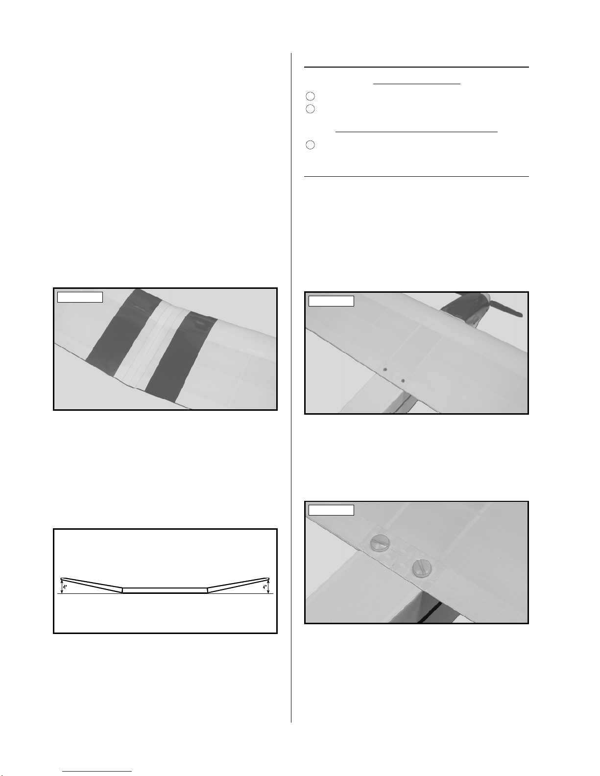
❑8) Set the motor between the handles of a pair
of needle nose pliers and secure the motor to the
handles using three rubber bands. This will keep
the motor secure enough for the break-in procedure.
See photo # 1 below.
❑9) Turn on the transmitter and plug the flight
battery into the speed control. If the motor turns on
immediately, use the throttle lever on the back of the
transmitter (Focus 3 only) to turn off the motor.
❑10) With the motor turned off, test the opera-
tionof thetwo servos.Both servosshould movewhen
you move the control stick.
❑11) Carefully spray a couple of light sprays of
Performance Plus Motor Spray inside the motor
openings and apply a small drop of Trinity Break-
In Drops onto each of the two motor bushings. See
photo # 2 below.
Photo # 1
Photo # 2
❑12) Using a couple of paper towels, wipe off
the excess motor spray and oil.
❑13) Slowly turn on the motor using the trans-
mitter throttle lever (Focus 3 only). Position the
throttle lever to about 1/3 throttle and let the motor
run. While the motor is running, apply a light spray
of motor spray inside the motor openings once every
minute, followed by a small drop of Break-In Drops
on each of the bushings. Do this until the battery is
fully discharged (i.e., the motor stops).
☛If you have chosen to usean on-off only motor
controller, complete the same process but only run
the motor in two-minute intervals, letting the motor
cool between each.
❑14) After the battery has discharged and the mo-
tor has stopped, spray motor spray through the motor
openings until the fluid runs clear. Apply a couple of
drops of Break-In Drops to the bushings and wipe
away all of the excess using paper towels.
❑15) Reinstall the motor, propeller assembly and
canopy. Reverse the removal steps for installation.

9
Photo # 3
❑7) Using a modeling knife, cut out two 2” long
pieces of colored tape.
❑8) While holding the outer wing panel at the
proper angle, apply one piece of tape to the top of the
wing joint at the leading edge and one piece at the
trailing edge. This will help temporarily hold the
wing panels in position.
☛When doing this make sure the two wing panels
are still pushed firmly together. There shouldn't be
any gap between the two panels.
❑9) Remove the wing from the work table and
turn it over, hanging the outer wing panel over the
edge of the table.
PARTS REQUIRED
❑{1} Center Wing Panel
❑{1} Right Wing Panel
❑{1} Left Wing Panel
❑{2} 3mm x 60mm Steel Pins
❑{2} 3mm x 20mm Steel Pins
❑{1} Roll of Colored Tape
2
3
4
9
TOOLS AND SUPPLIES REQUIRED
❑Excel Modeling Knife
❑12” Straight Edge Ruler
6
WING ASSEMBLY
JOINING THE WING PANELS
10
12
13
☛The three wing panels are held together using
four steel pins and colored tape. The steel pins hold
the wing panels at the proper angle and give the joints
their strength. The colored tape prevents the wing
panels from pulling apart. This type of construction
requires no glue to assemble the wing panels and the
wing panels can be easily removed for storage or
transport.
❑1) Using a ruler, locate the two predrilled holes
in each end of the center wing panel and remove the
coveringfrom overthemusing amodeling knife. One
hole is located 1-5/16” in front of the trailing edge
and the second hole is located 4-13/16” in front of
the trailing edge. See photo # 3 below.
❑2) Using a ruler, locate the two predrilled holes
in the root ribs of each outer wing panel and remove
the covering from over them using a modeling knife.
One hole is located 1-5/16” in front of the trailing
edge and the second hole is located 4-13/16” in front
of the trailing edge.
❑3) Working with the left outer wing panel for
now, carefully push one 3mm x 60mm steel pin into
the forward hole and one 3mm x 20mm steel pin into
the rear hole.
❑4) Firmly push both steel pins into place until
they both bottom out and can't be pushed in any
farther. See photo # 4 below.
Photo # 4
❑5) Line up the two predrilled holes in the left
end of the center wing panel with the two steel pins
you just installed in the outer panel. Gently push the
two wing panels together until they are fully seated.
❑6) Lay the center wing panel flat on your work
table. With both wing panels pushed firmly to-
gether, use a ruler and measure the distance from
the wing tip (at the trailing edge) to the top of your
work table. This measurement should be about 4”.
See figure # 1 below.
Figure # 1

10
❑Large Flat Blade Screwdriver
❑10) While making sure that the wing panels are
still firmly pushed together, carefully apply a long
piece of colored tape to the bottom of the wing joint.
Work slowly from the leading edge to the trailing
edge pushing the tape down as you go. Use a model-
ing knife to remove the excess tape.
❑11) Turn the wing right side up and set it on
your work table. Use a ruler to double check that the
outer wing panel is still at the proper angle.
❑12) While holding theouter panelin place, care-
fully apply a long piece of colored tape to the top of
the wing joint. Work slowly from the leading edge
to the trailing edge, pushing the tape down as you
go. Use a modeling knife to remove the excess tape.
See photo # 5 below.
Photo # 5
❑13) Repeat steps # 3 - # 12 to install the right
outer wing panel to the center wing panel assembly.
☛When installing the right wing panel, it is im-
portant that the measurement from the tip of the panel
(at the trailing edge) to your work table is the same
measurement as the left wing panel was when you
installed it. See figure # 2 below.
Figure # 2
☛To remove the wing panels for transport use a
modeling knife to cut through the tape. You can then
easily pull the panels apart. When you get to the
field you can simply push the wing panels back to-
gether and use a strip of tape (make sure you save the
roll of tape) to secure them in place.
PARTS REQUIRED
❑{1} Fuselage w/Motor and Propeller Assembly
❑{2} 6mm x 15mm Nylon Bolts
1
11
5
TOOLS AND SUPPLIES REQUIRED
WING INSTALLATION
❑1) Set the fuselage right side up on your work
table and place the wing into the wing saddle. Align
the brass insert in the leading edge of the wing with
themachine screwin thefuselage's forwardbulkhead.
❑2) Carefully slide the wing forward, making
sure the brass insert slides over the machine screw in
the forward bulkhead. See photo # 6 below.
INSTALLING THE WING BOLTS
Photo # 6
❑3) Insert the two 6mm x 15mm nylon bolts
through the two predrilled holes in the top of the wing
and thread them into the plywood mounting block
preinstalled in the fuselage. Tighten the two screws
securely using a large flat blade screwdriver. See
photo # 7 below.
Photo # 7
☛To help align the wing bolts with the threaded
holes in the plywood mounting block, you may need
to move the trailing edge of the wing one way or the
other until the bolts begin to thread into place.
☛The bolts only need to be tightened lightly. Do
not overtighten them or you might crush the wing.

11
❑# 1 Phillips Head Screwdriver
❑Large Flat Blade Screwdriver
❑Excel Modeling Knife
❑Needle Nose Pliers
❑12” Straight Edge Ruler
PARTS REQUIRED
❑{1} Horizontal Stabilizer w/Elevator
❑{1} Vertical Stabilizer w/Rudder
❑{2} 1.5mm x 500mm Pushrod Wires w/Z-Bends
❑{2} 2mm Flat Washers
❑{2} 2mm Hex Nuts
5
6
2
TOOLS AND SUPPLIES REQUIRED
TAIL GROUP INSTALLATION
ALIGNING THE HORIZONTAL STABILIZER
❑4) Remove the two wing bolts and the wing and
set them aside for now.
7
14
15
5
6
❑1) Using a modeling knife, remove the cover-
ing from over the two predrilled holes in the middle
of the stabilizer and from the slot in the stabilizer's
leading edge. One hole is located 1-1/2” in front of
the trailing edge and the second hole is located 3” in
front of the trailing edge. See photo # 8 below.
Photo # 8
❑2) Using a modeling knife, remove the cover-
ing from over the two predrilled holes in the top of
the stabilizer mounting platform. One hole is located
1-1/2” in front of the rear edge of the fuselage and
the second hole is located 3” in front of the rear edge
of the fuselage. See photo # 9 below.
Photo # 9
8
❑3) Using a modeling knife, remove the cover-
ing from over the two predrilled holes in the bottom
of the fuselage. The holes are located directly below
the two predrilled holes in the stabilizer mounting
platform.
❑4) Using a modeling knife, remove the cover-
ing from over the elevator and rudder pushrod exit
slots in the fuselage sides. One slot is located on
each side of the fuselage, 2-5/8” in front of the back
edge of the fuselage and 1/2” below the top of the
stabilizer mounting platform.
❑5) Working with one 1.5mm x 500mm pushrod
wire for now, insert the Z-bend into the third hole
out from the base of the elevator control horn. Ori-
entate the pushrod wire so that the longer portion of
the wire faces toward the center of the stabilizer. See
photo # 10 below.
❑6) Turn the stabilizer right side up and carefully
insert the plain end of the elevator pushrod wire into
the slot in the right side of the fuselage.
❑7) Carefully push the stabilizer into place until
it rests on top of the stabilizer mounting platform.
☛While pushing the stabilizer into place be care-
ful not to bend the elevator pushrod wire. When the
stabilizer is in place you will notice that the plain
end of the pushrod wire is visible inside the servo
compartment.
MOUNTING THE STABILIZERS
❑8) Uninstall the nylon rudder control horn us-
ing a # 1 phillips screwdriver to remove the two
machine screws. Set the control horn, backplate and
screws aside for now.
❑9) Align the two threaded steel rods in the ver-
tical stabilizer with the two predrilled holes in the
top of the horizontal stabilizer.
Photo # 10
13

12
❑10) Carefully push the vertical stabilizer down
until the two threaded rods exit the two holes in the
bottom of the fuselage. To make sure the stabilizers
are seated properly, firmly push down on the vertical
stabilizer, making sure the tab in the front of the ver-
tical stabilizer fits firmly into the notch in the
horizontal stabilizer. See photo # 11 below.
❑11) Turn the fuselage upside down. Slide one
2mm flat washer over each threaded rod, then thread
one 2mm hex nut onto each threaded rod. Tighten
the hex nuts firmly, using needle nose pliers to se-
cure the stabilizers in place. See photo # 12 below.
Photo # 12
CHECKING THE ALIGNMENT
❑12) Install the wing and bolt it securely into
place using a large flat blade screwdriver. Now check
to ensure that the horizontal stabilizer is aligned with
the wing. When viewed from the front, the horizon-
tal stabilizer should be level with the wing. See
figure # 3 below.
Figure # 3
☛If the stabilizer is not level with the wing, loosen
the two hex nuts and carefully slide a thin shim un-
der the low side of the stabilizer. Retighten the hex
nuts and check the alignment once more. Repeat this
procedure until you are satisfied that the alignment
is correct.
Photo # 11 INSTALLING THE RUDDER PUSHROD
❑13) Working with the second 1.5mm x 500mm
pushrod wire, insert the Z-bend into the fourth hole
out from the base of the control horn that you re-
moved from the rudder earlier. Orientate the pushrod
wire so that the longer portion of the wire faces the
right side of the control horn. See photo # 13 below.
Photo # 13
❑14) Carefully insert the plain end of the rudder
pushrod wire into the slot in the left side of the fuse-
lage. Slide the wire in until the control horn lines up
with the predrilled holes in the rudder.
❑15) Reinstallthe controlhorn tothe rudderusing
the two machine screws and the nylon backplate you
removed earlier. Tighten the machine screws using a
# 1 phillips screwdriver. See photo # 14 below.
Photo # 14
☛Be careful not to overtighten the screws. You
don't want to crush the wood.
☛Note that the longer portion of the pushrod wire
should come out on the top side of the control horn.
A=A-1

13
❑Pacer Thread-Lock
❑# 1 Phillips Head Screwdriver
❑# 2 Phillips Head Screwdriver
❑Wire Cutters
❑Electric or Hand Drill
❑5/64” Drill Bit
❑12” Straight Edge Ruler
❑Masking Tape
TOOLS AND SUPPLIES REQUIRED
❑#1 Phillips Head Screwdriver
❑Electric or Hand Drill
❑1/16” Drill Bit
2
SERVO INSTALLATION
ALIGNING THE SERVOS
❑1) Locate the two servos you intend to use for
the elevator and rudder controls.
❑2) Carefully install the four rubber grommets
and four brass collets onto each of the servo mount-
ing lugs. For proper vibration reduction, the brass
collets should be inserted into the rubber grommets
withthe flangesfacing thebottom ofthe servomount-
ing lugs. See figure # 4 below.
Figure # 4
❑3) Carefully removethe hatch coverthat istack-
glued to the bottom of the fuselage.
☛If you have difficulty removing the hatch cover,
carefully run the blade of your modeling knife along
the seams and carefully "pop" the hatch cover out.
❑4) Position theservosonto thepreinstalled servo
rails, making sure that you run the servo wires below
the back rail and out the hatch in the bottom of the
fuselage. Pay close attention to the positions of the
servo output shafts. They should both face the back
of the fuselage. See photo # 15 below.
Photo # 15
10
11
☛Make sure that when you install the two servos
that they are pushed together and centered between
the fuselage sides as shown in photo # 15. This will
ensure that the servo horns do not touch the fuselage
sides when they are installed later.
MOUNTING THE SERVOS
❑5) Using a drill with a 1/16” drill bit, drill eight
pilot holes through the servo rails for the eight servo
mounting screws included with your radio system.
☛Drilling pilot holes through the servo rails will
prevent the rails from splitting when the screws are
installed and tightened.
❑6) Using a # 1 phillips screwdriver, install and
tighten the mounting screws firmly to hold the ser-
vos in place.
SERVO HORN INSTALLATION
PARTS REQUIRED
❑{2} Adjustable Servo Connector Assemblies
8
1
TOOLS AND SUPPLIES REQUIRED
INSTALLING THE ELEVATOR
SERVO CONNECTOR
2
3
9
10
12
13
❑1) Locate one plastic "4-point" servo horn that
came with your servo. Each of the arms should have
at least three holes in them.
❑2) Using a pair of wire cutters, carefully remove
one of the plastic arms.
❑3) Using a drill with a 5/64” drill bit, enlarge
the third hole out from the center of the arm opposite
the one you cut off.
15

14
Photo # 16
❑4) Slide one adjustable servo connector
through the hole you enlarged. Apply a drop of
Pacer Thread-Lock to the nut, then thread the nut
into place. When you thread the nut on, don't tighten
it completely. You don't want the connector loose,
but you do want it to be able to rotate without bind-
ing too much. See photo # 16 below.
☛The Thread-Lock will secure the nut in place
and prevent it from loosening during flight.
☛Before starting the next few steps, please make
sure you have read and completely understood how
your radio control system and ESC operate.
❑5) Per yourradio systemguide andESC instruc-
tions, plug the flight battery into the ESC, then plug
the ESC and the elevator servo lead into their proper
slots in the receiver. Turn on the radio system.
❑6) Check to make sure the elevator control stick
and the elevator trim lever are centered.
❑7) Slide the adjustable servo connector/servo
horn assembly over the end of the elevator pushrod
wire and align the servo horn with the servo output
shaft.
❑8) Attach the servo horn to the output shaft,
making sure that the servo horn is centered. See
photo # 17 below.
INSTALLING THE SERVO HORN
Photo # 17
❑9) Use a couple of pieces of masking tape, taped
between the horizontal stabilizer and the elevator, to
hold the elevator centered.
❑10) With the elevator servo horn centered, use
a # 2 phillips screwdriver and tighten the machine
screw in the adjustable servo connector.
❑11) Using a # 1 phillips screwdriver, install and
tighten the servo arm retaining screw, provided with
your servo, to secure the servo horn into place.
❑12) Remove the masking tape from the elevator
and double check that the elevator and the elevator
servo are still centered.
❑13) With your radio system plugged in and
turned on, check the direction the elevator control
surface moves and the amount of deflection. To do
this pull back on the elevator control stick. The el-
evator should move up. If it does not, flip the servo
reversing switch on your transmitter to change the
direction. (Refer to your radio guide for more infor-
mation on this function.)
❑14) Pull back completely on the elevator con-
trol stick. While holding the control stick fully back,
use a ruler and measure the amount the trailing edge
of the elevator moves up. This measurement should
be 3/8”. See figure # 5 below.
ADJUSTING THE ELEVATOR PUSHROD
Figure # 5
❑15) If the control surface deflection is more or
less than 3/8” it must be changed. If your radio is
equipped with End Point Adjustments (EPA), make
thoseadjustments usingthe transmitter.(Refer toyour
radio guide for further details.) If your radio does
not have this feature, you can still make the adjust-
ments to the pushrod manually.

15
❑16) If the elevator is moving more than 3/8”,
move the adjustable servo connector in one hole to-
ward the center of the servo horn to decrease the
control deflection. If the elevator is moving lessthan
3/8”, move the Z-bend one hole closer to the base of
the control horn to increase the control deflection.
When adjusted properly, the elevator should move
3/8” both up and down.
INSTALLING THE RUDDER
SERVO CONNECTOR
❑17) Locate one plastic "4-point" servo horn that
came with your servo. Each of the arms should have
at least three holes in them.
❑18) Using a pair of wire cutters, carefully re-
move one of the plastic arms.
❑19) Using a drill with a 5/64” drill bit, enlarge
the third hole out from the center of the arm opposite
the one you cut off.
❑20) Slide one adjustable servo connector
through the hole you enlarged. Apply a drop of
Pacer Thread-Lock to the nut, then thread the nut
into place. When you thread the nut on, don't tighten
it completely. You don't want the connector loose,
but you do want it to be able to rotate without bind-
ing too much. See photo # 18 below.
❑21) Per yourradio systemguide and ESCinstruc-
tions, plug the flight battery into the ESC, then plug
the ESC and the rudder servo leads into their proper
slots in the receiver. Turn on the radio system.
Photo # 18
☛The Thread-Lock will secure the nut in place
and prevent it from loosening during flight.
INSTALLING THE SERVO HORN
❑22) Check to make sure the rudder control stick
and the rudder trim lever are centered.
❑23) Slide the adjustable servo connector/servo
horn assembly over the end of the rudder pushrod
wire and align the servo horn with the servo output
shaft.
❑24) Attach the servo horn to the output shaft,
making sure that the servo horn is centered. See
photo # 19 below.
Photo # 19
❑25) Use a couple of pieces of masking tape,
taped between the vertical stabilizer and the rudder,
to hold the rudder centered.
❑26) With the rudder servo horn centered, use a
#2 phillipsscrewdriverand tightenthe machinescrew
in the adjustable servo connector.
❑27) Using a # 1 phillips screwdriver, install and
tighten the servo arm retaining screw, provided with
your servo, to secure the servo horn into place.
❑28) Remove the masking tape from the rudder
and double check that the rudder and the rudder servo
are still centered.
❑29) With your radio system plugged in and
turned on, check the direction the rudder control sur-
face moves and the amount of deflection. To do
this push right on the rudder control stick. The rud-
der should move right. If it does not, flip the servo
reversing switch on your transmitter to change the
direction. (Refer to your radio guide for more in-
formation on this function.)
ADJUSTING THE RUDDER PUSHROD

16
❑30) Push right completely on the rudder control
stick. While holding the control stick fully right, use
a ruler and measure the amount the trailing edge of
the rudder moves right. This measurement should
be 1/2”. See figure # 6 below.
Figure # 6
❑31) If the control surface deflection is more or
less than 1/2” it must be changed. If your radio is
equipped with End Point Adjustments (EPA), make
thoseadjustments usingthe transmitter.(Refer toyour
radio guide for further details.) If your radio does
not have this feature, you can still make the adjust-
ments to the pushrod manually.
❑32) If the rudder is moving more than 1/2”,
move the adjustable servo connector in one hole to-
ward the center of the servo horn to decrease the
control deflection. If the rudder is moving less than
1/2”, move the Z-bend one hole closer to the base of
the control horn to increase the control deflection.
When adjusted properly, the rudder should move 1/2”
both right and left.
FINAL ASSEMBLY
PARTS REQUIRED
❑{1} 2mm x 10mm Wood Screw
❑{2} 25mm x 50mm Velcro©Strips
13
TOOLS AND SUPPLIES REQUIRED
❑# 1 Phillips Head Screwdriver
❑Excel Modeling Knife
❑Adjustable Wrench
❑Wire Cutters
❑Electric or Hand Drill
❑5/64” Drill Bit
❑12” Straight Edge Ruler
❑Pen or Pencil
INSTALLING THE RECEIVER
❑1) Using amodeling knife, cuta pieceof Velcro©
1-3/4” long. Remove the protective backing from
one side and firmly adhere the Velcro©to the bottom
of the receiver.
16
2
6
7
9
10
12
13
14
❑2) Remove theprotectivebacking fromthe other
side of the Velcro©and install the receiver onto the
two plywood rails inside the hatch in the bottom of
the fuselage. Press down firmly on the receiver to
secure it into place. See photo # 20 below.
Photo # 20
☛Make sure you install the receiver with the an-
tenna facing the back of the airplane.
❑3) Plug the elevator and rudder servo leads into
their proper slots in the receiver. Wrap the wires up
and push them between the receiver and the fuselage
side to keep them out of the way.
❑4) Using a drill with a 5/64” drill bit, drill a hole
through the right side of the fuselage, about 1” up
from the bottom and directly across from the back of
the receiver.
☛Becareful notto drillinto the sideof the receiver.
❑5) Unwrap the receiver antenna and carefully
feed it out through the hole in the fuselage side.
❑6) Using wirecutters,carefully makean antenna
mount out of an extra servo horn. Cut the arm into
the shape shown. See figure # 7 below.
Figure # 7
❑7) Using a drill with a 5/64” drill bit, enlarge
the two holes in the servo arm that the antenna will
pass through.

17
❑8) Secure the antenna to the bottom of the
threaded vertical stabilizer mounting rod using a
small rubber band and the modified servo arm. See
photo # 21 below.
Photo # 21
☛Adjust the modified servo arm so that the an-
tenna is not pulled too tightly. You don't want to put
too much strain on it.
☛Do not cut off the excess antenna. Let the ex-
cess hang behind the airplane. If you cut the antenna
it will greatly reduce the range of the receiver and
you will lose control of the airplane.
INSTALLING THE ESC
❑9) Uninstall the canopy using a # 1 phillips
screwdriver to remove the six wood screws. Set the
canopy and wood screws aside for now.
❑10) Slide the two motor leads on the ESC under
the balsa battery plate and out toward the motor.
❑11) Connect the red and black leads from the
motor to the red and black motor leads on the ESC.
❑12) Slide the ESC throttle lead between the ser-
vos and the fuselage side and into the hatch
compartment. Plug the lead into the proper slot in
the receiver.
❑13) Using a modeling knife, remove the cover-
ingfrom overthe switchcutout andthe armingswitch
hole if your ESC is equipped with an arming switch;
otherwise leave the hole covered. Both cutouts are
located on the left side of the fuselage, directly be-
low the forward section of the wing saddle, and are
visible from inside the fuselage.
❑14) Slide thearmingswitch intoplace andthread
the hex nut onto it. Lightly tighten the nut using an
adjustable wrench to secure it into place.
❑15) Remove the machine screws and faceplate
❑18) Carefully push the ESC up under the balsa
battery plate, making sure that the battery connector
on the ESC stays accessible.
❑19) Reinstall the canopy using the six wood
screws you removed previously. Tighten the screws
firmly, using a # 1 phillips screwdriver, to hold the
canopy securely in place.
Photo # 22
INSTALLING THE FLIGHT BATTERY
❑20) Remove the protective backing from one
side of the second piece of Velcro©and firmly adhere
the Velcro©to one side of the flight battery.
❑21) Remove the protective backing from the
other side of the Velcro©and set the battery onto the
balsa battery plate in the fuselage. The top end of the
battery pack should be below the wing saddle.
❑22) Press down firmly on the battery pack to
secure it into place. See photo # 23 below.
Photo # 23
from the switch. Align the hole in the faceplate with
the cutout in the fuselage side and use a pen to mark
the locations of the two mounting holes.
❑16) Using a drill with a 5/64” drill bit, drill two
holesthrough thefuselageside atthe twomarks made.
❑17) Mount the switch using the faceplate and
thetwo machinescrewsyou removedpreviously. Use
a # 1 phillips screwdriver to tighten the screws. See
photo # 22 below.

18
INSTALLING THE HATCH COVER
❑23) Locate the hatch cover that you removed
earlier. Using a ruler and a pen, place a mark in the
center of the hatch cover, 3/16” back from the front
edge. See photo # 24 below.
Photo # 24
❑24) Set the hatch cover into place and align the
edgesof thehatch coverwith thesides ofthe fuselage.
❑25) Using a drill with a 5/64” drill bit, drill a
hole down through the hatch cover and through the
plywood mounting block inside the fuselage.
☛Be careful not to drill down into the receiver!
❑26) To hold the hatch cover in place, install and
tighten the 2mm x 10mm wood screw using a # 1
phillips screwdriver. See photo # 25 below.
Photo # 25
BALANCING
TOOLS AND SUPPLIES REQUIRED
❑12” Straight Edge Ruler
❑Masking Tape
BALANCING THE THERMALAIRE EP
❑1) It is critical that your airplane be balanced
correctly. Improper balance will cause your airplane
to lose control and crash. The center of gravity is
located 2-1/2” back from the leading edge of the
wing, at the fuselage sides. This location is
13
15
recommended for initial test flying and training. The
C.G. can be moved aft up to 3/8”, but it is not recom-
mended that the C.G. be located any farther back than
2-7/8” behind the leading edge of the wing.
☛The Thermalaire EP should be balanced with
the flight battery securely mounted in the fuselage.
❑2) Install the wing onto the fuselage using the
two nylon bolts to secure it in place. Tear off two
short pieces of masking tape and place them on the
bottom of the wing, 2-1/2” back from the leading
edge, at the fuselage sides.
❑3) Place your fingers on the masking tape and
carefully lift the airplane. If the nose of the air-
plane falls, the airplane is nose heavy. To correct
this, remove the wing and move the flight battery
back just far enough to bring the airplane into bal-
ance. If the tail of the airplane falls, the airplane is
tail heavy. To correct this, remove the wing and
move the flight battery forward only enough to bring
the airplane into balance. When balanced correctly,
the airplane should sit level or slightly nose down
when you lift it up with your fingers.
☛Because the battery tray is mounted at an angle,
moving the flight battery up and down the tray will
still cause a change in the C.G.
☛Once you have flown and become familiar with
the flight characteristics of the Thermalaire EP, the
balance point (C.G.) can be moved aft up to 3/8” to
change the flight performance. Moving the balance
point back will cause the airplane to be more respon-
sive, but less stable; however, moving the C.G. back
willalso maximizeThermal-Air EP'sthermaling abil-
ity. Do not fly the Thermal-Air EP beyond the
recommendedbalance rangeor anuncontrollable
crash could result!
❑1) We recommend setting up the Thermal-Air
EP using the control throws we recommended in the
pushrod installation steps. Those controls throws are
suggested for initial test flying. If you haven't set up
the control throws yet, we have listed them again on
page # 19.
CONTROL THROWS

19
Please refer back to those pages for the proper tech-
nique for adjusting the control throws. These settings
will allow the airplane to fly smoother and make it
easier to control.
TEST FLYING AND TRAINING
Elevator: 3/8” up 3/8” down
Rudder: 1/2” right 1/2” left
❑1) Check the operation of the throttle.
❑A) Plug in your flight battery and turn on
the radio system.
CAUTION If you are using an ESC that is not
equipped with an arming switch, do not turn the re-
ceiver on unless the transmitter is turned on first.
Always turn the transmitter on first. Never allow
hands or clothing to get in the way of the propeller
when the radio is turned on. Sudden unwanted radio
signals, or turning the radio on with the throttle lever
set at full throttle, can turn the motor on unintention-
ally. Always make sure that the throttle lever is set
to idle before turning on the transmitter.
❑B) If your ESC is equipped with an arming
switch, press the switch once to allow power to the
motor. When the throttle lever is at the idle position,
the motor should be off. Moving the lever should
turn on the motor. Gradually moving the lever to the
full forward position should result in the motor run-
ning at full power.
☛Some ESCs will give you more proportional
control than others. Your ESC may also have a
manual control adjustment screw that must be ad-
justed prior to using the ESC. (Refer to your ESC's
operating guide for further information.)
❑2) If you did not yet break-in the motor, refer to
page # 7 and follow the instructions for motor break-
in. Correct break-in will result in higher performance
and longer motor life. It is highly recommended.
PREFLIGHT CHECK
❑3) Cycle the motor battery three times. When
NiCad batteries are new they need to be used 2-3
times before they will produce their top voltage and
duration. To cycle them, simply charge the battery
and then run the motor until the motor stops. Allow
the battery and motor to cool, then repeat this proce-
dure two more times.
❑4) Check the condition of the transmitter bat-
teries. They should be fully charged if they are
rechargeabletype NiCads,or replacedif theyare non-
rechargeable cells and the voltage indicator drops out
of the green.
❑5) Check every bolt and glue joint in the
Thermal-Air EP to ensure that everything is tight and
well bonded.
❑6) Double check the balance of the airplane. Do
this with the flight battery securely mounted in the
airplane.
❑7) Check the control surfaces. They should
move in the correct direction and not bind.
❑8) If yourradiotransmitter isequippedwith dual
rate switches double check that they are on the low
rate setting for your first few flights.
❑9) Check to ensure that the control surfaces are
moving the proper amount.
❑10) Check the receiver antenna. It should be
fully extended and not coiled up inside the fuselage.
SAFETY
The following are our general guidelines for your
safety and the safety of others. Please read and un-
derstand these safety guidelines before going out to
the flying field for the first time.
❑1) Do not test fly your model for the first time
without first having it safety-checked by an experi-
enced modeler.
❑2) Do not fly your model higher than approxi-
mately 400 feet within 3 miles of an airport without
having an observer with you. The observer should
tell you about any full size aircraft in your vicinity
and you should always give the right of way to full
scale aircraft.

20
❑3) When flying at a flying field with established
rules, you should abide by those rules. You should
not deliberately fly your model in a reckless and/or
dangerous manner.
❑4) While flying, you should not deliberately fly
behind the flight line. If your model should inad-
vertently fly behind the flight line, you should change
course immediately.
❑5) Don't drink and fly. Consuming alcoholic
beverages prior to flying, or while you are flying, is
a big no-no.
❑6) You should complete a successful range
check of your radio equipment prior to each new day
of flying, or prior to the first flight of a new or re-
paired model.
❑7) You should perform your initial turn after
takeoffaway from theflightline and/orspectator area.
❑8) You should not knowingly operate your R/C
radio system within 3 miles of a preexisting model
club flying field without a frequency sharing agree-
ment with that club.
If you've come this far, now you're ready to pre-
pare for the maiden voyage of your new airplane.
Before proceeding, we highly recommend double
checking all of your work. Make sure there is no
detail you missed and that you understand all of the
airplane's functions. We hope you find the follow-
ing sections helpful, making your first flights
successful.
Since you've chosen the Thermalaire EP, you've
avoided the most common mistake beginners make:
choosing a high performance airplane like the P-51
Mustang or the F-16 jet as a trainer. Just as you
wouldn't learn to drive a car using an Indy car, you
shouldn't use a high performance airplane to learn to
fly R/C model airplanes. The second mistake new
pilots make is not seeking out the help of an experi-
enced modeler. While it is certainly true that some
people have learned to fly without help, having the
helpof anexperienced R/Cmodelpilot willhelp make
those first few flights much more successful and en-
joyable. We highly recommend seeking out a club
or a flying field near you. You'd be surprised just
how many clubs there are that help beginners.
ABC'S OF FLYING
Once at the field, even before removing your air-
plane from the car, introduce yourself to some of the
other pilots. Find out what safety procedures and
frequency control system is in place. In short, learn
and follow the field etiquette. Doing so will ensure
safe flying for you and others. You will also be able
to find out who might be the right person to help you
learn to fly.
Sometimes, it is just impossible to find anyone
to help. In that case it would be wise to seek out
some additional information about flying. R/C Mod-
eler Magazine, Harry Higley and Model Airplane
News Magazine all publish very good basic flight
training books that explain flying in greater depth.
You may also wish to seek out a computer simulator.
There are several different brands of flight simula-
tors available that can be very effective at teaching
the basic coordination of R/C flight.
If you do decide you have no choice but to learn
to fly on your own, choosing the place to fly your new
airplane is of the utmost importance. Select your po-
tential flying field with the following considerations:
1) Look for a site that has a soft landing area.
The best sites are large grassy fields.
2) The fewer ground obstructions the better. No
trees, buildings or large rocks should be nearby.
3) Nopeople orhouses shouldbe nearby. While
R/C flying is generally safe, it can lead to harm or
injury. Do nottry to flyyour modelif there arehouses
or people close by.
4) There should be no high-lines, telephone
lines or electrical lines anywhere near where you are
flying. If your airplane accidentally does fly into
wires of any kind, do not try to retrieve it yourself.
Serious injury or even death could result. Contact
the local police or fire department to help you in re-
trieving your airplane.
To begin you should know how your airplane op-
erates. First,there arefour forcesoperatingon aflying
aircraft: Lift, Weight, Thrust and Drag. The motor
willcreate thrustto overcomethe drag. Intimes when
the motor is off, gravity pulling the airplane down can
act as thrust. This is how the airplane flies when the
BASICS OF FLIGHT
Table of contents
Other Academy of Model Aeronautics Toy manuals
Popular Toy manuals by other brands

THUNDER TIGER
THUNDER TIGER F-8F BEARCAT - ASSEMBLY manual

H-KING
H-KING FG-1 Corsair Lucky Gallon instruction manual

REVELL
REVELL 24064 manual

Fisher-Price
Fisher-Price Classical Chorus 74120 instruction sheet

marklin
marklin 39894 user manual

WARCRADLE STUDIOS
WARCRADLE STUDIOS Dystopian Wars MOZHAYSKI BATTLEFLEET Assembly instructions

Fisher-Price
Fisher-Price DALE EARNHARDT JR L6345 Owner's manual & assembly instructions

Marvel
Marvel Avengers Iron Man quick start guide

Carrera RC
Carrera RC 301005 Assembly and operating instructions

Mattel
Mattel Barbie CMT17 instructions

REVELL
REVELL KIT 5201 Assembly manual

Roc Hobby
Roc Hobby swift operating manual