Changes
The material in this document is for information only and is subject to change without
notice.
Before You Begin
Before going through this manual, you should read and focus on the following safety
guidelines. Notes about the subsystem’s controller configuration and the product
packaging and delivery are also included here.
Safety Guidelines
To provide reasonable protection against any harm on the part of the user and to
obtain maximum performance, user is advised to be aware of the following safety
guidelines particularly in handling hardware components:
Upon receiving the product:
Place the product in its proper location.
Do not try to lift it by yourself alone. Two or more persons are needed to remove
or lift the product to its packaging. To avoid unnecessary dropping out, make
sure that somebody is around for immediate assistance.
It should be handled with care to avoid dropping that may cause damage to the
product. Always use the correct lifting procedures.
Upon installation of the product:
Ambient temperature is very important for the installation site. It must not
exceed 30◦C. Due to seasonal climate changes; regulate the installation site
temperature making it not to exceed the allowed ambient temperature.
Before plugging-in any power cords, cables and connectors, make sure that the
power switches are turned off. Disconnect first any power connection if the power
supply module is being removed from the enclosure.
Outlets must be accessible to the equipment.
All external connections should be made using shielded cables and as much as
possible should not be performed by bare hand. Using anti-static hand gloves is
recommended.
In installing each component, secure all the mounting screws and locks. Make
sure that all screws are fully tightened. Follow correctly all the listed procedures
in this manual for reliable performance.
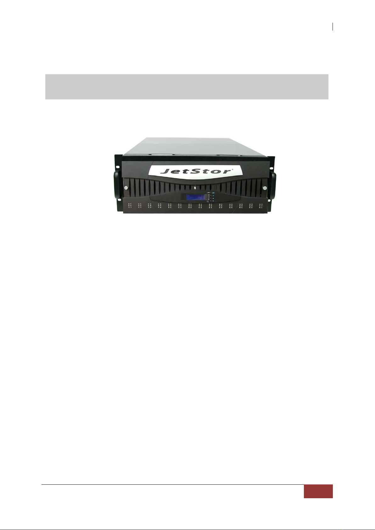
Controller Configurations
This JetStor SAS 742JD supports dual JBOD controller configurations.
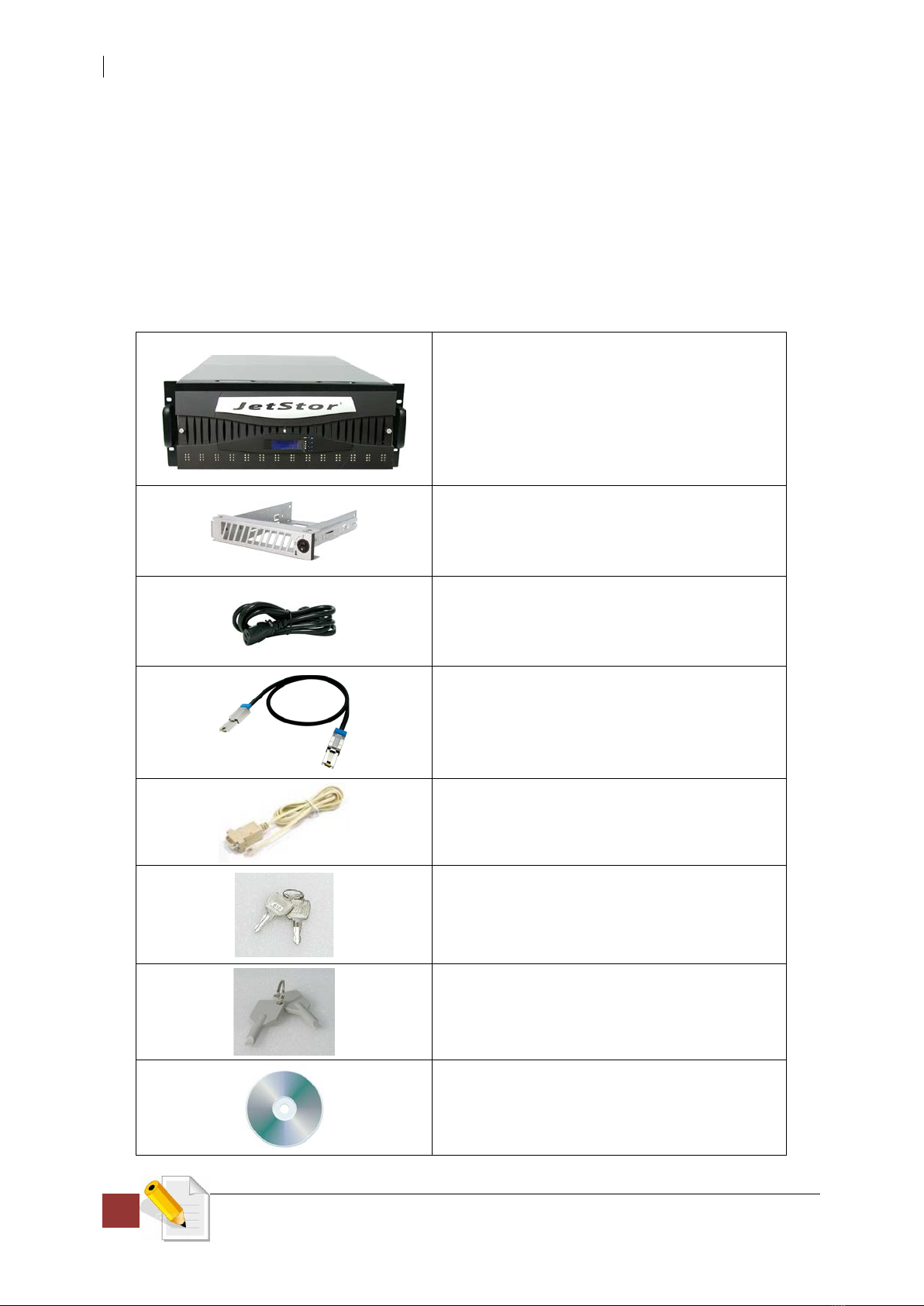
Packaging, Shipment and Delivery
Before removing the subsystem from the shipping carton, you should visually
inspect the physical condition of the shipping carton.
Unpack and verify that the contents of the shipping carton are complete and in
good condition.