Acclaim Lighting Flex 120 User manual

www.acclaimlighting.com Flex 120
User guide


1
www.acclaimlighting.com
CONTENTS
INTRODUCTION ......................................................2
Welcome 2
Safety 2
Maintenance 2
Cleaning 2
Supplied items 3
Accessories 3
INSTALLATION.........................................................4
Mounting 4
Connections 6
Dimming control 7
FURTHER INFORMATION ........................................8
Troubleshooting 8
Specifications 9
Limited product warranty 10

2www.acclaimlighting.com
INTRODUCTION
WELCOME
Welcome to Flex 120 from Acclaim Lighting. Flex 120 is a low profile, exterior rated linear
LED strip that can be directly powered from AC mains dimmers to fit seemlessly with
existing control systems. Fully sealed lengths are supplied from 1.64 feet (0.5m) up to 65 feet
(20m), with custom lengths also available to order. As an integral part of each installation, all
Flex 120 strips must be mounted and protected within matching aluminum channels (two
styles and three lengths available). Matching diffusion lenses are also available.
DMX or 0-10V control can be added by using the optional Acclaim Lighting UDM unit.
A choice of of emitters with white color temperatures from 2700K to 5000K is offered, in
addition to saturated single colors.
SAFETY
•The supply circuit must be fed via a Ground-Fault Circuit Interrupter (GFCI) / Residual
Current Device (RCD) breaker.
•Ensure that the power input is supplied from a correctly fused and environmentally
protected location.
•This product is rated at IP66 for wet and dry locations, however, it must not be installed
where water can accumulate.
•Ensure that each Flex 120 strip is fully protected within matching aluminum mounting
channels.
MAINTENANCE
CAUTION: Always isolate mains power before starting maintenance operations.
•Ensure that all mounting (and device) screws/bolts are fully tight and free of corrosion.
•Ensure there is no deformation to the housing, lenses or fixing points.
•Check that all power supply cables are free from physical damage or material fatigue.
•Use only genuine spare parts supplied by Acclaim Lighting.
CLEANING
•Use a moist, lint-free cloth when cleaning each fixture.
•Never use alcohol or solvents.

3
www.acclaimlighting.com
SUPPLIED ITEMS
ACCESSORIES
Flex 120 strip with connection
box and feed cables
Low prole aluminum channel
1.64’ (0.5m) [FACCH500]
3.28 (1m) [FACCH1000]
6.56’ (2m) [FACCH2000]
Tall prole aluminum channel
1.64’ (0.5m) [FACTPC500]
3.28 (1m) [FACTPC1000]
6.56’ (2m) [FACTPC2000]
Lenses for all channels
Clear Frosted Opal
1.64’ (0.5m) [FACCL500] [FACFL500] [FACOL500]
3.28 (1m) [FACCL1000] [FACFL1000] [FACOL1000]
6.56’ (2m) [FACCL2000] [FACFL2000] [FACOL2000]
Rolling wheel
install tool
[FACIT]
UDM
Converts 0-10V or DMX
to mains dimming

4www.acclaimlighting.com
INSTALLATION
Flex 120 strips are supplied in lengths ranging from 0.5m (1.64’) to 20m (65.6’) and are fully
sealed at manufacture. Custom lengths are also available to order.
IMPORTANT
•Flex 120 strips MUST NOT be cut after manufacture - doing so will expose mains level
power rails and will void your warranty.
•Flex 120 strips are rated at IP66 for wet and dry locations, however, they must not be
installed where water can accumulate.
MOUNTING
Flex 120 strips must be installed within specially designed aluminum channels in order to
provide protection as well as a neat finish.
Aluminum channels are supplied in two heights: Tall profile (20mm) and Low profile (12mm):
Each style of channel is available in three lengths: 0.5m, 1m and 2m. Each can be cut to
length as required.
All channels have pre-drilled mounting holes (3mm) located at 200mm centers and are
supplied with a matching number of screws (M3 x 15): 3, 5 or 10 as appropriate to the
chosen channel length.
Note: If you need to use alternative mounting screws, ensure that the screw heads do not rise
more than 2mm, otherwise they will not fit flush within the channel and will interfere with the Flex
120 strip when it is installed.
When installing in precise or tight spaces, ensure that sufficient clearances are left at either
end of the channels to accommodate the feed-in and termination moldings. At the feed-
in end you will also need to allow extra space for the cable access as well as the 70mm
molding:
0.47”
(12mm)
0.75”
(19mm)
0.79”
(20mm)
0.75”
(19mm)
Optional
lens
Tall prole
Flex 120
strip
Low prole
2.76”
(70mm)
1.1”
(28mm)
Feed-in
molding Channel Termination
molding

5
www.acclaimlighting.com
MOUNTING (CONTINUED)
Lay one end of the Flex 120 strip into the channel and gently push the strip down to seat it
in place. For best results use the wheeled install tool [part #: FACIT] to run along and position
the strip correctly. The tool has an indented center so that it places pressure onto the
outside edges of the strip without stressing the LED emitters.
Wheeled
install tool
Once the Flex 120 strip is in place you can fit the lens(es), if used. Insert the lens at one end
of the channel and gently press it down until it clicks into place. Then run your hand along
the lens to clip the remainder into place.
Do NOT use screwdrivers or
other implements to apply
pressure to Flex 120 strips.

6www.acclaimlighting.com
N
L
CONNECTIONS
Each Flex 120 strip is supplied with an IP66-rated connection box. The box has a Ø0.87”
(22mm) opening for a suitable conduit fixing and includes a 10’(3m) feed cable with IP67
output connector. The connector links directly with the one fitted to each Flex 120 strip.
11.8” (300mm)
strip cable
10 ‘ (3m)
feed cable
IP66-rated connection box
Remove the four screws securing the lid to reveal the connectors and 6.3AL250V (5x20mm,
6.3A fast acting) glass fuse.
Note: There is a termination point for an earth connection, however, this does not pass through to
the Flex 120 strip and is not a requirement for correct operation.
Output to
Flex 120 strip
Glass fuse 6.3AL250V
(5x20mm, 6.3A fast acting)
Input via conduit xing.
120VAC (RMS) maximum.
Earth connection not required.
Please see page 9
for full dimensional
diagrams.
Note: The supply circuit must be fed via a
Ground-Fault Circuit Interrupter (GFCI) /
Residual Current Device (RCD) breaker.

7
www.acclaimlighting.com
Flex 120 strips are compatible with the two types of dimmer circuits shown below. However,
they are NOT suitable for use with TRIAC-based dimmers, also known as Forward phase-
control or Leading-edge dimmers.
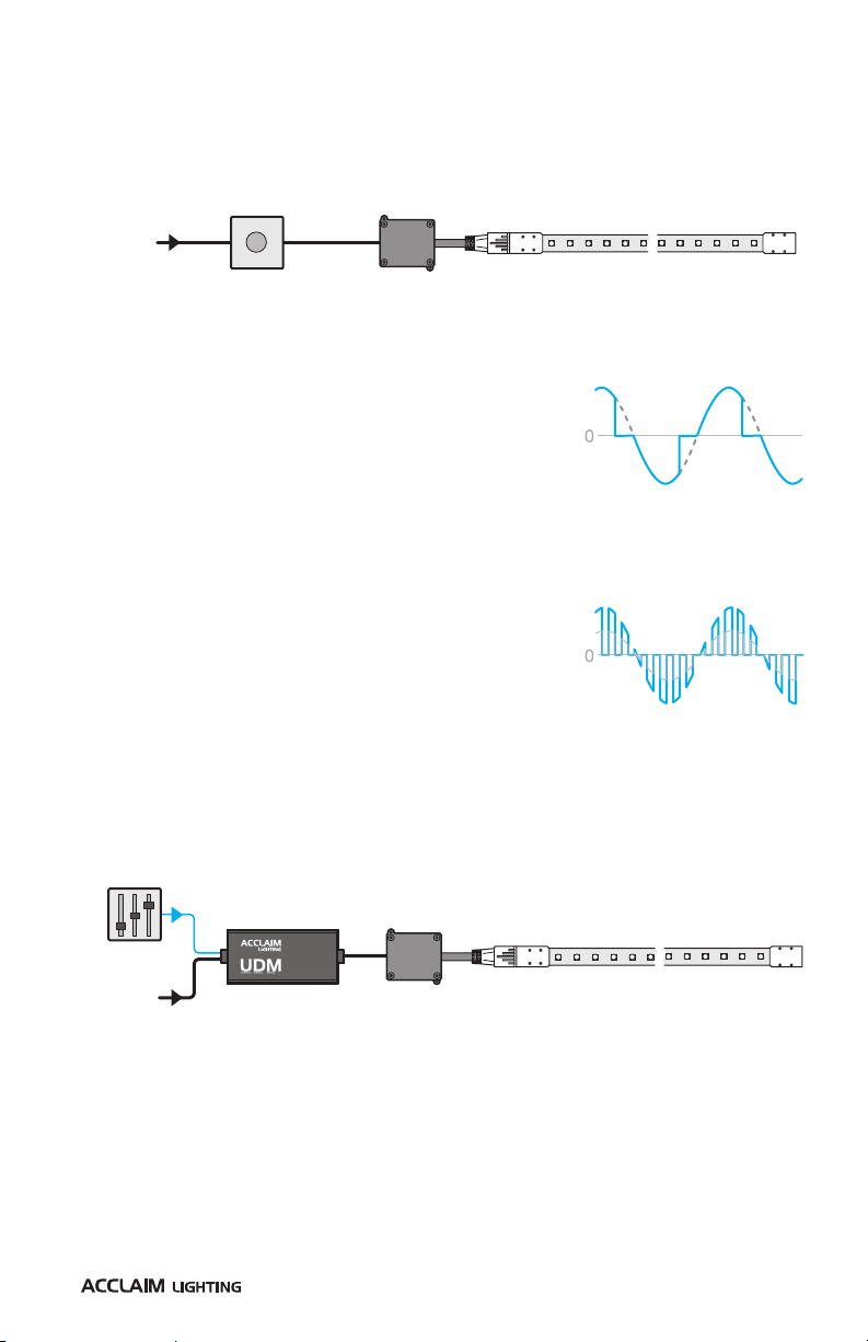
ELV dimming - (Electronic Low Voltage) - These dimmers use
a transistor type device to cut off the mains output before
the zero point of each half-wave cycle, thus they affect the
trailing edge of the mains sinewave. These dimmers avoid the
voltage spikes associated with TRIAC-switched leading edge
dimmers and are best suited to dimming capacitive loads
such as the electronic transformers used with low voltage
lighting. This style of dimming is also called Reverse phase-
control or Trailing-edge dimming.
Sinewave dimming - These dimmers use an IGBT (Insulated
Gate Bipolar Transistor) to switch the mains output at high
frequencies such that they can recreate a dimmed mains
sinewave with a varying overall amplitude. These dimmers
produce the smoothest output of all types.
DMX OR 0-10V CONTROL
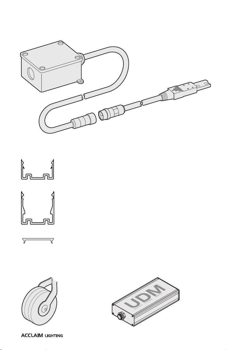
Additionally, Flex 120 strips can be controlled by either DMX or 0-10V (source or sink) inputs by
using the optional Acclaim Lighting UDM (Universal Dimming Module):
DIMMING CONTROL
Each Flex 120 strip can accept dimmed mains power at 120VAC (RMS) originating from
certain types of dimmers, such as domestic (ELV) wall dimmers (connect according to
dimmer specifications):
The UDM runs from a standard mains input (120VAC) and uses a DMX or 0-10V (source or sink)
input to create a dimmed mains output from which the Flex 120 strip(s) can operate.
The UDM is able to provide fully dimmed output power from 0-100%.
MAINS
POWER
Standard (ELV)
wall dimmer
MAINS
POWER
DMX or 0-10V
CONTROL

8www.acclaimlighting.com
FURTHER INFORMATION
TROUBLESHOOTING
NO LIGHT OUTPUT IS VISIBLE WHEN EXPECTED.
•Check that power is correctly applied to the fixture and that there is no damage to the
power input cord.
•If external DMX control is being used, check that the DMX address set within the fixture
matches that being output by the controlling source device.

9
www.acclaimlighting.com
Release 1.0a
SPECIFICATIONS
Colors 2700K, 3000K, 3500K, 4000K, 5000K, Red, Green, Blue or Amber
Photometrics Up to 371 lumens per 1.64’(0.5m) section, CRI >80
Beam angle 160o
Lumen maintenance (L70) 50,000 hours (25oC)
Operating voltage 120VAC
Power consumption 3.8W per foot, 12.4W per meter
Control ELV (reverse phase) or sinewave dimming, 0-10V*, DMX*
* requires the use of the optional UDM module)
Ingress protection IP66, wet and dry location - not for use where water can
accumulate, GFCI/RCD breaker required
Impact protection IK08, protection against 5 joule impact
Connectors 10’ (3m) feed cable and UL listed AC junction box included
Finish Transparent sleeve, white PCB
Mounting Via aluminum channel
Operating temperature -40oF to 122oF (-40oC to 50oC)
Certifications
2.76” (70mm) 1.64’ (0.5m) to 65.6’ (20m)
1.1”
(28mm)
1.77”
(45mm)
3.43” (87mm)
0.75”
(19mm)
2.95”
(75mm)
2.76”
(70mm)
3.07”
(78mm)
0.43”
(11mm)
0.51” (13mm)
2.87” (73mm)

10 www.acclaimlighting.com
LIMITED PRODUCT WARRANTY
A. Acclaim Lighting™ hereby warrants, to the original purchaser, Acclaim Lighting finished products
to be free of manufacturing defects in material and workmanship for a standard period of:
•Fixtures: 5 Years (1,825 days) from the date of purchase.
•Drivers, power supplies and accessories: 5 Years (1,825 days) from the date of purchase.
•Flex Products: 3 Years (1,095 days) from the date of purchase.
•Controllers: 2 Years (730 days) from the date of purchase.
It is the owner’s responsibility to establish the date and place of purchase and warranty
terms by acceptable evidence, at the time service is sought.
B. For warranty service, send the product only to the Acclaim factory. All shipping charges
must be pre-paid. If the requested repairs or service (including parts replacement) are
within the terms of this warranty, Acclaim Lighting will pay return shipping charges only
to a designated point within the United States. If the entire instrument is sent, it must be
shipped in its original package. No accessories should be shipped with the product. If any
accessories are shipped with the product, Acclaim Lighting shall have no liability whatsoever
for loss of or damage to any such accessories, nor for the safe return there of. Acclaim
reserves the right to replace the item with same or similar product at its discretion.
C. This warranty is void if the serial number has been altered or removed; if the product is
modified in any manner which Acclaim concludes, after inspection, affects the reliability of
the product; if the product has been repaired or serviced by anyone other than the Acclaim
Lighting factory unless prior written authorization was issued to purchaser by Acclaim
Lighting; if the product is damaged because not properly maintained as set forth in the
instruction manual.
D. This is not a service contract, and this warranty does not include maintenance, cleaning
or periodic check-up nor do we guarantee as part of this warranty any lumen performance
during period. Parts not covered by this warranty include: fuses, external power supplies,
third party items not manufactures by Acclaim lighting. During the period specified above,
Acclaim Lighting will replace defective parts at its expense, and will absorb all expenses
for warranty service and repair labor by reason of defects in material or workmanship. The
sole responsibility of Acclaim Lighting under this warranty shall be limited to the repair
of the product, or replacement thereof, including parts, at the sole discretion of Acclaim
Lighting. At no time will installation or re-installation or products labor or liability costs will
be assumed by Acclaim Lighting. All products covered by this warranty were manufactured
after January 1, 2012, and bear identifying serial number marks to that effect.
E. Acclaim Lighting reserves the right to make changes in design and/or improvements
upon its products without any obligation to include these changes in any products
theretofore manufactured No warranty, whether expressed or implied, is given or made
with respect to any accessory supplied with products describe above. Except to the extent
prohibited by applicable law, all implied warranties made by Acclaim Lighting in connection
with this product, including warranties of merchantability or fitness, are limited in duration
to the warranty period set forth above. And no warranties, whether expressed or implied,
including warranties of merchantability or fitness, shall apply to this product after said
period has expired.
F. Marine or extreme weather location applications using Acclaim lighting products are
subject to a 2 year limited warranty and Acclaim must be notified prior to delivery of units
for such applications so that preventative treatment can be made to the products to ensure
proper performance and product life with a special marine code coating / sealing process at
an additional cost.
G. The consumer’s and or dealer’s sole remedy shall be such repair or replacement as is
expressly provide above; and under no circumstances shall Acclaim Lighting be liable for
any loss or damage, direct or consequential, arising out of the use of, or inability to use,
this product. This warranty is the only written warranty applicable to Acclaim Lighting
products and supersedes all prior warranties and written descriptions of warranty terms and
conditions heretofore published.

11
www.acclaimlighting.com

www.acclaimlighting.com
Table of contents
Other Acclaim Lighting Light Fixture manuals
Popular Light Fixture manuals by other brands

Patriot Lighting
Patriot Lighting 130910 Assembly and installation instructions

Lightolier
Lightolier WES SERIES 2X4 specification

Cooper Lighting
Cooper Lighting AMETRIX C-Scroll P1R installation instructions

Cooper Lighting
Cooper Lighting MS280D instruction manual

Event Lighting
Event Lighting M1H300W user manual

American Dynamics
American Dynamics AD1020-1541 datasheet

Larson Electronics
Larson Electronics LED25WRE-LENSCOVER instruction manual

Lightronics
Lightronics FXLD818FRP4I Specifications

Maximus
Maximus SPL08-07A1N4-ORB instruction manual

Stairville
Stairville MH-575 S MKII Pro-Spot user manual

Nebula
Nebula NBL-MS400 user manual

VIBIA
VIBIA North Assembly instructions