Entry+ module EVK hardware user guide
Page 3 of 27
2023-03-29 © 2023 by Acconeer – All rights reserved
Table of Contents
1. Overview of the XE125 Entry+ Module Evaluation Kit ................................................................. 4
1.1. Introduction ............................................................................................................................. 4
1.2. Getting Started ......................................................................................................................... 5
2. Software for the EVK ...................................................................................................................... 6
2.1. SW download .......................................................................................................................... 6
2.2. SW API Description ................................................................................................................ 6
3. The EVK Hardware ......................................................................................................................... 7
3.1. XE125 Evaluation Board ......................................................................................................... 9
3.1.1. Overview ......................................................................................................................... 9
3.1.2. Power ............................................................................................................................... 9
3.1.3. Not Mounted Components ............................................................................................ 10
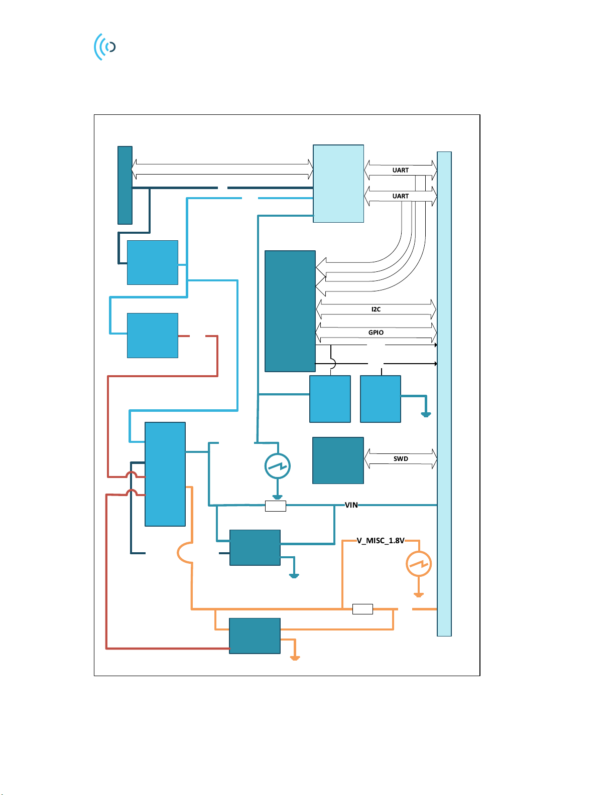
3.1.4. Electrical Schematic ...................................................................................................... 11
3.1.5. Bill of Material .............................................................................................................. 15
3.1.6. Component Placement Drawing .................................................................................... 15
3.1.7. Connectors ..................................................................................................................... 17
3.2. XM125 Entry+ Module ......................................................................................................... 19
3.2.1. Overview ....................................................................................................................... 19
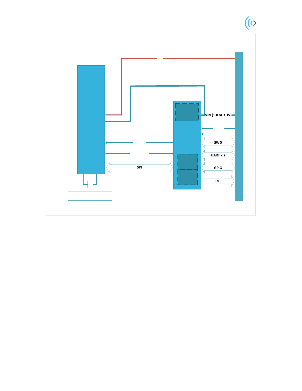
Electrical Schematic ...................................................................................................................... 20
3.2.2. Bill of Material .............................................................................................................. 22
3.2.3. Land Grid Array ............................................................................................................ 22
4. Safety ............................................................................................................................................. 24
4.1. Electrostatic precautions ........................................................................................................ 24
5. Regulatory Information ................................................................................................................. 25
6. Revision History ............................................................................................................................ 26
7. Disclaimer ..................................................................................................................................... 27