Acconeer XE121 User manual

PCR sensor A121 EVK hardware user
guide
- XE121, XC120, XS121

A121 EVK – User Guide
2
Proprietary and Confidential
© 2022 by Acconeer – All rights reserved 2022-07-07
PCR sensor A121 EVK hardware user guide
- XE121, XC120, XS121
Author: Acconeer
Version 1.0: 2022-07-06
Acconeer AB

A121 EVK – User Guide
3
Proprietary and Confidential
2022-07-07 © 2022 by Acconeer – All rights
reserved
Table of Contents
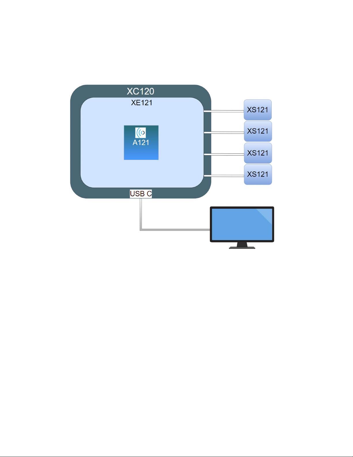
1. Overview of the A121 Evaluation Kit ............................................................................................. 4
1.1 Introduction ............................................................................................................................. 4
1.2 Getting Started ......................................................................................................................... 5
2. Software for the EVK ...................................................................................................................... 6
2.1 SW download .......................................................................................................................... 6
2.2 SW API Description ................................................................................................................ 6
3. The EVK Hardware ......................................................................................................................... 7
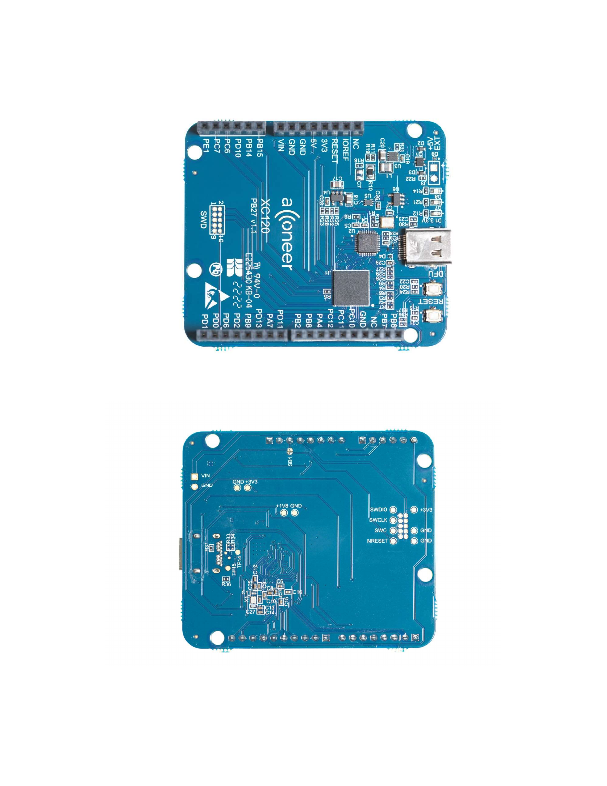
3.1 XC120 Connector Board ......................................................................................................... 8
3.1.1 Overview ......................................................................................................................... 8
3.1.2 Power ............................................................................................................................. 11
3.2 XE121 Evaluation Board ....................................................................................................... 12
3.2.1 Overview ....................................................................................................................... 12
3.2.2 Electrical Schematics..................................................................................................... 15
3.2.3 Bill of Material .............................................................................................................. 21
3.2.4 Pinning ........................................................................................................................... 22
3.3 XS121 Satellite Board ........................................................................................................... 24
3.3.1 Overview ....................................................................................................................... 24
3.3.2 Electrical Schematics..................................................................................................... 26
3.3.3 Bill of Material .............................................................................................................. 28
3.4 Lens kits – LH120 and LH112 .............................................................................................. 29
3.4.1 Overview ....................................................................................................................... 29
3.4.2 LH120 - Contents and assembly .................................................................................... 29
3.4.3 LH112 - Contents and assembly .................................................................................... 31
3.5 Design considerations ............................................................................................................ 33
4 Safety ............................................................................................................................................. 34
4.1 Electrostatic precautions ........................................................................................................ 34
5 Regulatory Information ................................................................................................................. 35
6 Revision History ............................................................................................................................ 36
7 Disclaimer ..................................................................................................................................... 37

A121 EVK – User Guide
4
Proprietary and Confidential
© 2022 by Acconeer – All rights reserved 2022-07-07
1. Overview of the A121 Evaluation Kit
1.1 Introduction
The A121 Evaluation Kit (The EVK) is a development platform featuring Acconeer’s latest radar
sensor, the A121. This is a low-power, high-precision 60 GHz radar in one package solution with
integrated baseband, RF front-end and antenna. It is pin compatible with its predecessor, A111, but
comes with improved power consumption and signal to noise ratio.
The A121 is based on pulsed coherent radar technology (PCR). It has leading-edge patented sensor
technology with pico-second time resolution. It is possible to realize use cases requiring ranges up to
20m and it supports mm accuracy on absolute distances and sub-mm accuracy on relative distances.
The A121 EVK consists of three boards that can be connected in different combinations:
XC120 (“Connector Board”)
XE121 (“Evaluation Board”)
XS121 (“Satellite Board”)
The XC120 board carries a cortex M7 MCU which is to be flashed with a software dedicated to stream
data from the A121 radar sensor to Acconeer’s “Exploration Tool” via USB HS 2.0. The XC120 is
intended to be used with the exploration server for streaming radar sensor data only and after flashing,
no further configuration by the user is expected.
The XE121 features an on board A121 pulsed coherent radar sensor and the possibility to add up to
four additional A121 radar sensors via FFC (Flat Flexible Cable) to the XS121 radar satellite boards.
The XE121 can’t be used stand-alone since it isn’t equipped with an MCU. It is designed to be
compatible with the XC120, Raspberry Pi and STM Nucleo-64 or Nucleo-144 development boards.
The most straight-forward and optimized way to evaluate the A121 radar sensor is to connect the
XE121 to the XC120 Connector board which enables evaluation of the radar sensor using the
Acconeer “Exploration Tool”1. Connecting the XE121 to the XC120 gives you the highest data
1 Available for download on github: https://github.com/acconeer/acconeer-python-exploration

A121 EVK – User Guide
5
Proprietary and Confidential
2022-07-07 © 2022 by Acconeer – All rights
reserved
streaming rate thanks to the USB HS 2.0 connection on the XC120 and the high SPI speed that is
possible to achieve when using the XC120 in combination with XE121. This document will focus
mainly on using XC120+XE121+XS121.
If you prefer, you can connect the XE121 to a Raspberry Pi, using the “Software Development Kit for
Raspberry Pi”. The rate at which you can retrieve data from the A121 is in this case limited by the
Raspberry Pi SPI interface speed.
Another option is to connect XE121 directly to an STM Nucleo-64 or Nucleo-144 development board
featuring the MCU of your choice. The main reason for making XE121 compatible with the STM
Nucleo development boards is to facilitate SW development, there is no support for this configuration
in Acconeer “Exploration Tool”. Acconeer provides a SW integration guideline “STM32CubeIDE
User Guide” to help you get started. Refer to the Acconeer Developer page for the different SW guides
and downloads: https://developer.acconeer.com/
1.2 Getting Started
A Quick Installation Guide is available at [youtube link] and a pdf variant can be downloaded from
https://developer.acconeer.com
This short instruction video will ensure a smooth setup and installation. For more information on
retrieving the Acconeer SW, please refer to the next chapter.

A121 EVK – User Guide
6
Proprietary and Confidential
© 2022 by Acconeer – All rights reserved 2022-07-07
2. Software for the EVK
2.1 SW download
The SW is available for downloading at https://developer.acconeer.com/
2.2 SW API Description
The Acconeer SW comes with an API (Application Programming Interface). Acconeer provides
several service oriented example applications, as well as customer guidelines for application
development when utilizing the API. All APIs provided by Acconeer are documented.
Open the SW zip file downloaded from Acconeer’s developer page. In the file structure, please locate
/doc.
doc/ contains API documentation in HTML format – simply open doc/html/index.html.

A121 EVK – User Guide
7
Proprietary and Confidential
2022-07-07 © 2022 by Acconeer – All rights
reserved
3. The EVK Hardware
Figure 1 shows the block diagram for the EVK
Figure 1 The EVK block diagram.

A121 EVK – User Guide
8
Proprietary and Confidential
© 2022 by Acconeer – All rights reserved 2022-07-07
3.1 XC120 Connector Board
3.1.1 Overview
The purpose of the XC120 board is to act as a high-speed USB bridge to the A121 Pulsed Coherent
Radar Sensor Evaluation Board XE121. The XC120 does NOT contain an A121 radar sensor and is
intended to be used together with XE121. Without the XE121, XC120 serves no purpose.
The XC120 board carries a cortex M7 MCU to stream radar sensor data from XE121 to Acconeer’s
“Exploration Tool” via USB HS 2.0.2 This board is intended to be used for streaming sensor data only
and after flashing, no further configuration by the user is expected. The XC120 is delivered with a
bootloader so that it can be flashed via the USB interface. For details on how to flash the XC120, refer
to the “A121 EVK Getting Started Guide”. The XC120 is connected to XE121 via pin headers. The
XE121 is designed to be compatible with STM Nucleo-64 and STM Nucleo-144 Development boards
and thus the pin headers on XC120 are placed in the same way. The XC120 is however NOT a Nucleo
development board and is not intended to be flashed with any SW not provided by Acconeer.
Figure 2 shows the block diagram of the XC120 Connector Board.
Figure 2. The block diagram of XC120.
Picture 1 and Picture 2 show the XC120 front and reverse sides.
2 Acconeer’s “Exploration Tool” is supported by Linux and Windows OS.

A121 EVK – User Guide
9
Proprietary and Confidential
2022-07-07 © 2022 by Acconeer – All rights
reserved
Picture 1. XC120 front side.
Picture 2. XC120 reverse side.

A121 EVK – User Guide
10
Proprietary and Confidential
© 2022 by Acconeer – All rights reserved 2022-07-07
Picture 3 shows XC120 connected to XE121 and one XS121. Picture 4 shows XC120 connected to XE121 and
four XS121 (fully loaded configuration).
Picture 3. XC120 connected to XE121 and one XS121.

A121 EVK – User Guide
11
Proprietary and Confidential
2022-07-07 © 2022 by Acconeer – All rights
reserved
Picture 4. XC120 connected to XE121 and four XS121.
3.1.2 Power
The XC120 connector board is powered via USB (5V, 500mA). This 5V power domain powers the
complete A121 EVK (XC120+XE121+XS121). For some use cases (when attaching more than one
XS121 board to XE121 and running simultaneous radar measurements on them), more power may be
needed. An external power supply can then be connected via J3 (not mounted pin header on XC120).
As soon as 5V is available on J3, the current is automatically drawn from the external power supply.
When the power LED D1 is lit on XC120, the board is powered on and ready for use. Refer to Picture
1 for details on J3 and D1 placement.

PCR sensor A121 EVK hardware user guide
Page 12 of 37
2022-07-07 © 2018 Acconeer – All rights reserved
3.2 XE121 Evaluation Board
3.2.1 Overview
The XE121 Evaluation Board is part of the Acconeer A121 Evaluation Kit and is intended to be used
together with the XC120, a Raspberry Pi or STM Nucleo-64 or STM Nucleo-144 development boards.
XE121 is equipped with 1 fixed A121 pulsed coherent radar sensor as well as 4 FFC (Flat Flexible
Cable) connectors to which XS121 satellite boards can be connected (optional). The flex cable
solution enables a wide variety of use cases involving multiple radar sensors. It also facilitates proof of
concepts since the radar sensor board placement is not limited by the size of the evaluation board. It is
not possible to run the XE121 without one of these “MCU boards” since the XE121 is not equipped
with an MCU for control and communication of the A121 pulsed coherent radar sensor. Figure 3
shows the block diagram of XE121:
Figure 3. The XE121 block diagram.
In the pictures below, the XE121 front and reverse sides are shown as well as how to connect it to
Raspberry Pi and STM Nucleo development boards.

A121 EVK – User Guide
13
Proprietary and Confidential
2022-07-07 © 2022 by Acconeer – All rights
reserved
Picture 5. XE121 front side.
Picture 6. XE121 reverse side.

A121 EVK – User Guide
14
Proprietary and Confidential
© 2022 by Acconeer – All rights reserved 2022-07-07
Picture 7. XE121 connected to Raspberry Pi.
Picture 8. XE121 connected to an STM Nucleo Development Board.

PCR sensor A121 EVK hardware user guide
Page 15 of 37
2022-07-07 © 2018 Acconeer – All rights reserved
3.2.2 Electrical Schematics
On the following pages, please find the schematics for the XE121:

A121 EVK – User Guide
16
Proprietary and Confidential
© 2022 by Acconeer – All rights reserved 2022-07-07

A121 EVK – User Guide
17
Proprietary and Confidential
2022-07-07 © 2022 by Acconeer – All rights reserved

A121 EVK – User Guide
18
Proprietary and Confidential
© 2022 by Acconeer – All rights reserved 2022-07-07

A121 EVK – User Guide
19
Proprietary and Confidential
2022-07-07 © 2022 by Acconeer – All rights reserved

A121 EVK – User Guide
20
Proprietary and Confidential
© 2022 by Acconeer – All rights reserved 2022-07-07
This manual suits for next models
2
Table of contents
Other Acconeer Motherboard manuals

Acconeer
Acconeer XM122 Installation manual

Acconeer
Acconeer LH112 User manual

Acconeer
Acconeer XM126 User manual

Acconeer
Acconeer Entry+ XE125 Installation manual

Acconeer
Acconeer XC111 User manual

Acconeer
Acconeer XM122 User manual

Acconeer
Acconeer XM112 User manual

Acconeer
Acconeer XC112 User manual

Acconeer
Acconeer XR112 User manual