Adaptive FAST 500 User manual


FAST 500, 510 & 525/550
Radar Speed Display Dolly
User Manual
Contents
1. Unpacking and Checking Carton
Contents
2. Location Selection
3. Setting Up for Use
4. Anti-theft Precautions
5. Fine Tuning / Aiming
6. Programming the Display
7. Readout Results
8. Advanced Features
9. Setting up the Clock and Timer
10. Charging the Battery
11. Maintenance, Cleaning, & Care
12. Technical Specifications
13. Options and Upgrades
14. Warranty
15. Trouble Shooting Tips
16. Contact Information
17. Data Recording Unit Instructions
Quick Start
Guide In-Depth
Guide
Adaptive Micro Systems LLC | 7840 North 86th Street | Milwaukee, WI 53224
Phone (800) 558-7022 | AdaptiveDisplays.com

Thank you for the purchase of an FAST 500, 510 or 525 Radar Speed Display Sign. The FAST 500 &
510 was designed for small community streets and school zones where speeding is a problem.
The Fast 525 is designed for industrial usage where forklift speeding and company traffic is an
issue. This Manual will guide you through the all of the aspects of using your new sign. Please
read and understand this Manual and review the checklist in Section 1 below to be sure that
you’ve received everything you need prior to starting.
Take a moment to record the model and serial numbers below so that you have them in a safe
place for future use. You’ll find them at the front of the sign as shown in Figure 1.
SERIAL NUMBER: ______________________________
DATE OF PURCHASE: ____________________________
OPTIONS PURCHASED:__________________________
1. UNPACKING AND CHECKING CARTON CONTENTS
Item Qty Description
A
C
D
E
F
G
H
I
(1) FAST 500/510/525 Radar Speed Display Dolly
(1) “YOUR SPEED” or “SCHOOL ZONE sign (mounted)
(1) “SPEED LIMIT” sign (mounted)
(3) “0”, “2”, & “3” numbered overlay signs
(1) “L” Key for signage (allen wrench)
(1) Key for sign enclosure
(1) Power Cord for charging (SpeedBoss includes external charger)
(1) Locking cable for wheel (Fast 500 only)
In addition you may have ordered on or more of the following options:
•Data collection system
•Optional Violator Alerts
Adaptive Micro Systems LLC | 7840 North 86th Street | Milwaukee, WI 53224
Phone (800) 558-7022 | AdaptiveDisplays.com
2. LOCATION SELECTION
In order to optimize your traffic calming results, there are a few simple things to keep in
mind and simple steps to follow. You’ll want to position the sign in location that’s on a
relatively flat stretch of road and is not too close to any stop signs, intersections, or
sharp curves in the road. Also, a clear line-of-sight relatively free of obstructions such as
large trees, fences or other landscape features is most desirable. Keep in mind that the
radar unit you’ve purchased is approach only (single-directional), so only the speed of
oncoming vehicles is displayed.
3. SETTING UP FOR USE
Park the dolly at final resting place, power it up, implement your anti-theft measures,
aim and go.
4. ANTI-THEFT PRECAUTIONS
We recommend a few ways to keep your dolly secure:
1. Run a locking cable thru one or both of your wheels and around the
frame.
2. Chain or cable-lock the sign to a nearby pole or other fixed landscape
feature.
5. FINAL POSITIONING / FINE TUNING
See Figures 5a and 5b for some basic dolly positioning tips. Keep in mind that the 12” tall
characters are readable to 750 feet. If the radar unit is picking up vehicles too far away,
simply rotate the sign clockwise so that it’s facing the opposite curb a bit more. Likewise,
if the unit is picking vehicles up too close or not far away enough, rotate counter-
clockwise. Practice with as many vehicles as necessary until desired results are achieved.
Remember, you may adjust the radar gun angle (aim) in the FAST 500/525 as well as the
angle of the dolly for maximum fine-tuning. See figure5b.
Figure 5a - Dialing in Approach Angle Sensitivity
Adaptive Micro Systems LLC | 7840 North 86th Street | Milwaukee, WI 53224
Phone (800) 558-7022 | AdaptiveDisplays.com
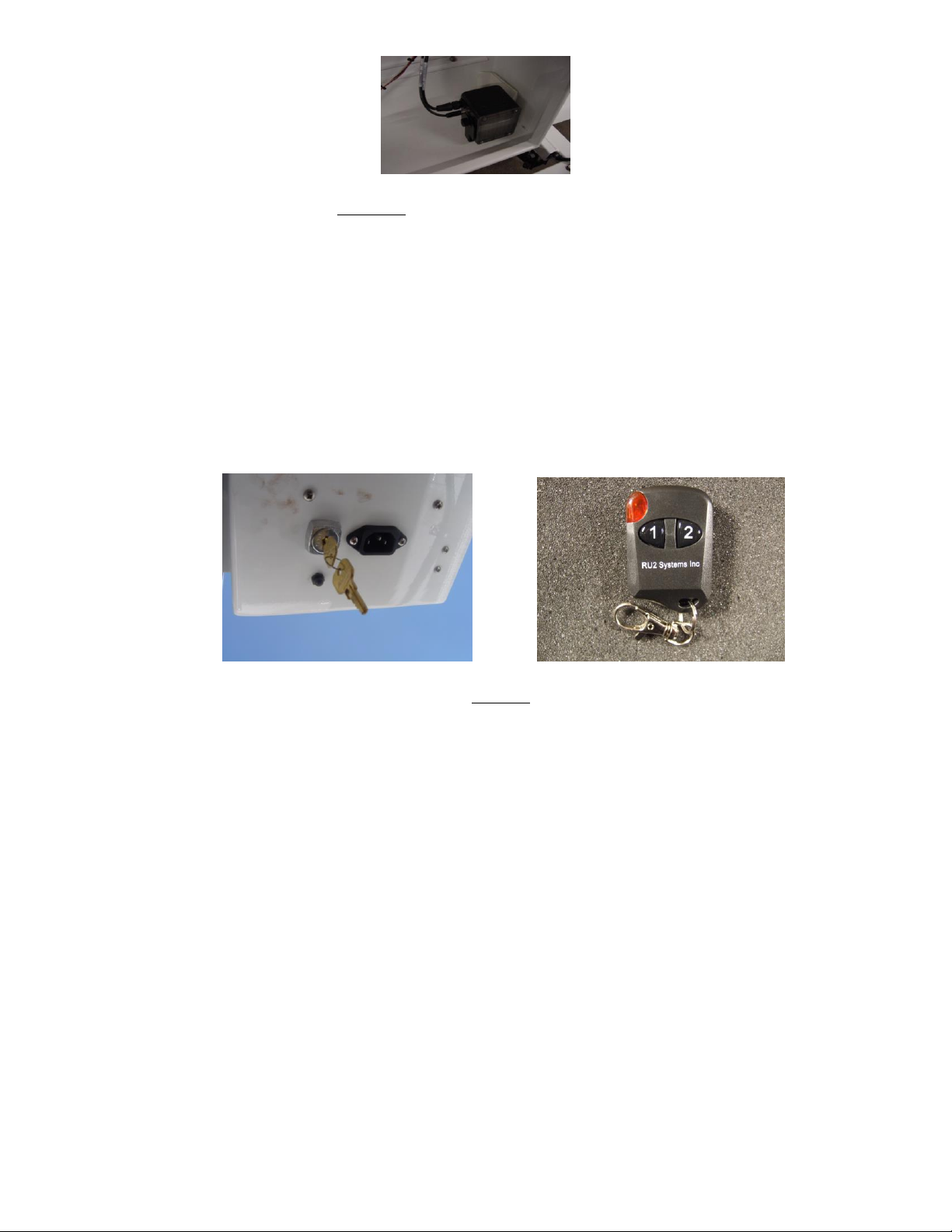
Figure 5b - Internal Radar Gun swivels both
Horizontally & vertically for diverse aiming options
6. PROGRAMMING THE DISPLAY
Now that your dolly is in position, and the “SPEED LIMIT” sign is set; you are ready to
power up. For the 510 Only - flip the toggle switch at the underside of the display
enclosure to “ON”. The 500/525 have a keyed on/off switch. Your display should light up
and flash a number between 0 and 9. This is the ambient light indicating level that
adjusts the LED’s brightness to meet the existing conditions automatically. Next locate
a small push button next to the “On/Off” switch on the bottom of the enclosure. This
programming button, or use your remote, will set up the display features on the FAST
500/510/525.
Figure 6
Key Chain Remote Control
•The left button directs the numbers up with the other directing down. When
the sign is in run mode, holding both buttons in for 1 second resets the sign
without having to cycle the power key.
•To replace its battery, remove the small Phillips head screw located on the
lower back and replace with a type 27A, 12volt alkaline cell.
The speed codes and their meanings
Read over the following programming codes listed in the Speed Code Table
below to become familiar with the two-letter groups (modes) you want to set in
the sign using the push button. Concentrate on the “Normal Mode” (NM) and
“Violator Alerts”
(VA) modes only, for now. Notice that they are grouped so that for example, when
“VA” is selected, you can set the “Minimum Speed”, Flash (speed), Blank (speed),
etc. As the last numbers are entered, the display is ready and goes blank.
Adaptive Micro Systems LLC | 7840 North 86th Street | Milwaukee, WI 53224
Phone (800) 558-7022 | AdaptiveDisplays.com

SPEED CODE TABLE
Two-letter Mode Meaning Description
NM => “Normal Mode” Sign shows all speeds
normally with no speed
filtering
VA => “Violator Alert”
MS => “Minimum. Speed”
SL => “Slow”
RB => “Red & Blue”
FL => “Flash”
BL => “Blank”
“Violator Alert” MENU
Min. speed for sign to display
Speed at which red “SLOW”
shows (Optional Feature)
Flashing “Red & Blue” speed
(Optional Feature)
Speed at which to flash
readout Speed at which to
blank screen
**ND => “No Display” Unit collects radar data with no display
** OPTIONAL ONLY for units with the
optional data collection software feature.
Feature must be enabled - See
Advanced Features Mode Section.
SETTING THE SIGN IN “NORMAL MODE”
The simplest mode to put the sign into is the “NM” (Normal
Mode). Instructions:
1. Turn the power on with the key. After the brightness number changes,
start pushing the button and stop on the two letter code “NM”.
2. As the display goes dark, it is now running in “Normal Mode”. In other
words, the sign will display the speed of oncoming vehicles from 5 mph
(down to 1 mph is also available, see Advance Features Section) to 99
MPH without showing any alerts. So for this code only, no further
programming would be needed.
PROGRAMMING THE SIGN IN “VIOLATOR ALERT” MODE
This section covers setting the standard “Violator Alert” functions including the
optional “Slow”, “Red & Blue” flashing signals. Note: The pushbutton
instructions described in the following paragraphs also apply to the use of the
key chain remote control buttons.
Turn power on. After the brightness number changes, push the button
and stop on “VA”. The display is now in “Violator Alert” setup mode. The Violator
Alerts 1 to 5 will then begin to appear in the order of the photos as shown
below.
Adaptive Micro Systems LLC | 7840 North 86th Street | Milwaukee, WI 53224
Phone (800) 558-7022 | AdaptiveDisplays.com
Note: If the Timer is enabled, (see Section 11 “Setting the Clock and Timed Events)
the sign will run in Violator Mode (or any other mode) only during the selected
event timed program. Otherwise, if the timer is disabled, the sign will run
continuously
(not recommended for overly long periods of time when on battery power only).
“Violator Alert”
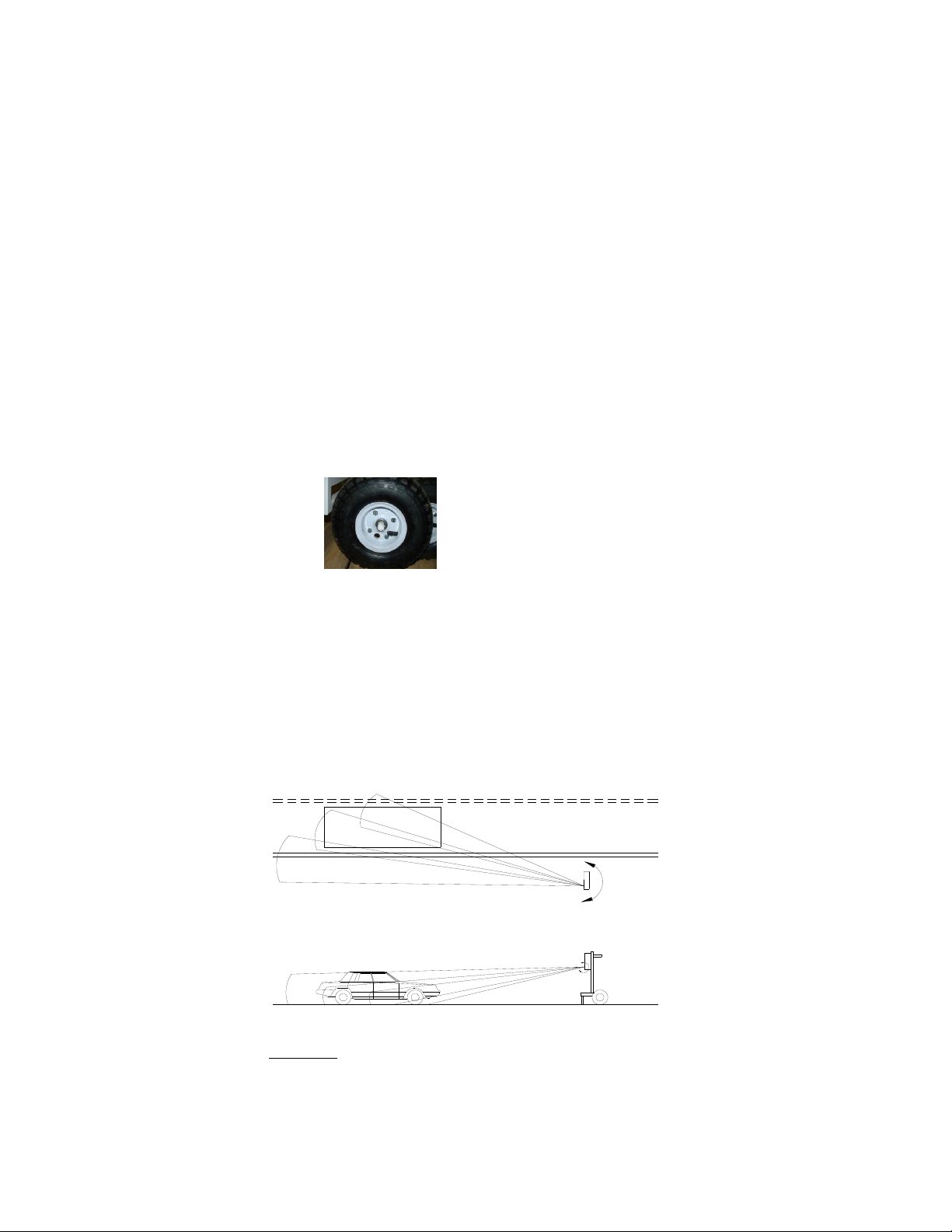
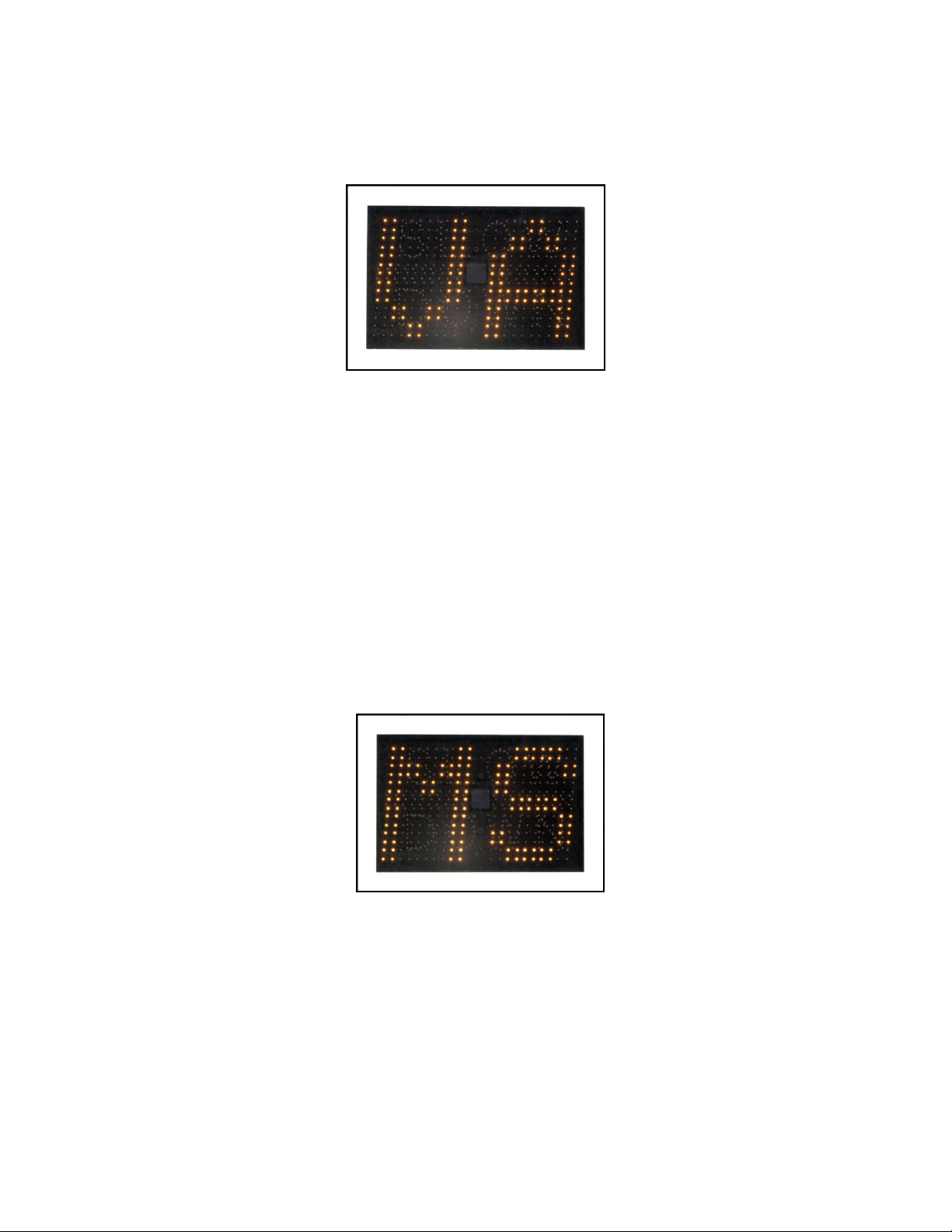
Violator Alert 1: MS - Minimum Speed
After seeing the “VA” screen, the display will show “MS” (see photo below) along
with a number. The number represents the lowest speed at which the display will
start showing all oncoming vehicles. When this number appears, the operator
has 5 seconds within to start pushing the button in order to program this “MS”
speed setting. Press the button until the desired speed setting is reached. (Note:
If the button is held down, the numbers will increment fast without having to
press the button many times. The numbers will start over after 99 if you miss your
desired speed without turning off the power. If using the key chain remote,
simply press either button to move the numbers forward or backward). Once the
desired setting is reached, stop and wait for the next screen to appear after
approximately 5 seconds. The screen will then change to the next screen for
speed setting.
“Minimum Speed”
Violator Alert 2: SL - SLOW (Optional Feature)**
Check your packing slip or order to verify that this optional feature has been
included with your product. If this feature was ordered, the display will now show
the red “SL” (Slow) message and show a speed setting number. The red “Slow”
message is effective in helping to calm traffic. When the operator sees the setting
number appear, push the button within 5 seconds in order to change this number
until the desired speed setting is reached. Note: You can set the numbers even
when the words “Slow” are flashing. Once the desired setting is reached, stop
pressing the button and wait for the next screen, after approximately 5 seconds.
Adaptive Micro Systems LLC | 7840 North 86th Street | Milwaukee, WI 53224
Phone (800) 558-7022 | AdaptiveDisplays.com

Violator Alert 3: RB - Red and Blue flashing lights (Optional Feature)**
Check your packing slip or order to verify that this optional feature has been
included with your product. If this feature was ordered, the display will now show
“RB” which effectively flashes the Red and Blue flashing light pattern at the driver
while displaying their speed. The operator has 5 seconds to start pushing the
button in order to change the number setting. Note: You can set the numbers
even when the “Red & Blues” are flashing. Press the button until the desired
speed setting is reached. Once the desired setting is reached, stop and wait for
the next screen after approximately 5 seconds.
Violator Alert 4: FL - Flashing Speed
The display will now show “FL”. When drivers go over this setting, they will see
their over-the-limit speed flash. The operator has 5 seconds to start pushing the
button in order to change the speed setting. Press the button until the desired
speed setting is reached. Once reached, stop and wait for the next screen to
appear after approximately 5 seconds.
“Flashing Speed”
Violator Alert 5: BL - Blanking Speed
The display will show “BL” which is the speed limit that the display will no longer
show the oncoming vehicles speed. This setting will prevent drivers from
increasing their speed over this speed limit to see how fast they can go. Press the
button until
Adaptive Micro Systems LLC | 7840 North 86th Street | Milwaukee, WI 53224
Phone (800) 558-7022 | AdaptiveDisplays.com

the desired speed setting is reached. Wait approximately 5 seconds and the sign
will go dark. The display is now in service and operating in “Violator Alerts”
mode.
“Blanking Speed”
** Optional SLOW and Flashing Red & Blue Violator Alerts can be purchased and
activated at any time. Call Customer Service 866-982-2107 for pricing and
information.
Notes: •After this last “BL” screen, all of the violator alert settings have been saved even
after the sign is switched off. When the sign is turned on again, it will run thru
all of the modes and their speed settings for the operator to review.
•If changes are needed, press the sign mounted button for 5 seconds which will
start the mode settings to display again. If using the key chain remote, hold the
left button in for 1 second for the same effect.
•If desired, the sign can be pre-set at your base facility for transportation and
set-up at a different location.
•The violator alerts can be set in any order, but not at the same speed. If
attempted, this setting will skip to the next available number. To get the best
effect from the alerts, set the speeds at least 3-4 MPH difference. If you wish to
not use one of the violator alert settings, set the speed high, i.e. 97 MPH.
•Holding the button will scroll through the numbers faster for quicker setup. If
the desired setting is passed, the numbers will start over after 99.
•If using the optional key chain remote, the left button advances the numbers
while the right button reverses them.
•To start over, either turn off/on the sign with the power key OR when using the
key chain remote, hold the left button in for 3 seconds for a power reset.
After setting the clock, (see Section 11 “Setting the Clock & Timed Events”) the
sign will revert back to Normal Mode (NM). If Violator Alert mode is desired, it
will have to be set to “VA” mode again.
Violator Alert Settings Summary
Push button until display shows “VA”
Wait five seconds for MS (Minimum Speed) to display
“MS” will display. Push the button to set the desired speed.
Wait five seconds for SL (SLOW) to display
“SL” is displayed. Push the button to set desired speed.
Wait five seconds for RB (Flashing Red & Blue) to display
“RB” is displayed. Push the button to set desired speed.
Wait five seconds for FL (Flashing Speed) to display
“FL” is displayed. Push the button to set desired speed.
Wait five seconds for BL (Blanking Speed) to display
“BL” is displayed. Push the button to set desired speed.
After five seconds the last speed sets and the display goes dark
Adaptive Micro Systems LLC | 7840 North 86th Street | Milwaukee, WI 53224
Phone (800) 558-7022 | AdaptiveDisplays.com

Traffic Set-Up Examples
35 mph neighborhood speed limit
Set the “MS” (the radar detected Minimum Speed limit) at 5 mph, the
“SLOW” message at 35, “Flashing Speed” at 40mph, the “Red & Blues” at
50 and the Blanking Speed at 60. This is what will happen: Oncoming
vehicles speeds will be shown on the sign traveling from 5 to 34 MPH. If
the vehicle is traveling 35 to 39, the SLOW message will flash. Between 41
and 49, their speed will be displayed while flashing. Over 50MPH, the
display will show the Red & Blue flashing lights pattern. At 60 and above,
the display is blank. As the vehicle slows, the appropriate “Violator Alert”
will show for their speed until they reach 34 MPH where their speed is
displayed normally.
School Zones
Set the “MS” (the radar detected Minimum Speed limit) at 15 mph (so
drivers in a school zone obeying the speed limit are not distracted), the
“Flashing Speed” at 16mph and the “Blanking Speed” for 40mph. This is
what will happen: For speeds under 15 MPH, no speed will be displayed.
The display will flash the speed for vehicles traveling between 16 and 39
MPH. No speed will be displayed above 40 MPH.
7. READOUT RESULTS
The readings from the radar unit are filtered. The radar unit is very sensitive, so for
continuity of the oncoming driver, not every reading may be displayed. If there is a
difference between vehicle speeds of more than 3 miles per hour per second (extreme
acceleration or deceleration), the display will simply hold the last recorded speed for a
few seconds rather than jumping back and forth between speeds. A couple of
examples:
Example 1:
Example 2:
If a vehicle is traveling at 35mph and the car behind him is traveling
at 40mph, the sign will display the first vehicle at 35 until it passes.
The first vehicle’s speed will show for 1-1/2 seconds after it passes,
so the radar can establish and display vehicle two’s speed at
40mph.
If a vehicle accelerates towards the sign from a stop at greater than
3 miles per hour per second, no speed will be displayed. If a vehicle
accelerates at 3 miles per hour per second or less, the sign will
display the speed as it increases.
Adaptive Micro Systems LLC | 7840 North 86th Street | Milwaukee, WI 53224
Phone (800) 558-7022 | AdaptiveDisplays.com

8. ADVANCED FEATURES
In addition to the standard features there are some advanced features available mainly
for trouble shooting.
To enter the Advanced Feature mode, turn the unit ON and press the programming
button five (5) times before the intensity number blinks. First an “A” will appear on the
left digit and a number on the right. Press the programming button until the
appropriate number is shown for that slot. Wait for a “B” to appear and repeat this for
“C” and “D” as well. This will put you into that mode until the unit is turned off and back
on again. See below a list of codes and slots for these advanced features.
A B C D
9 9 6 9
9 9 7 1
9 9 7 3
9 9 7 5
9 9 7 9
9 9 8 1
9 9 8 3
9 9 8 7
9 9 8 9
Minimum Speed Mode
Alternate Slow Down Mode
Demo mode (see further instructions)
Show Serial Number
Display Diagnostic Mode
Auto Intensity Diagnostic Mode
Turn On & Off Radar Acceleration Filter
Turn On & Off No Display Availability
Turn On & Off Set Time Availability
Minimum Speed Mode
Lower speeds of 5 mph are distracting in most applications but are desirable in some. As
a default, the display will only show down to 5 mph but down to 1 mph is available.
Putting in the minimum speed code will turn on and off the down to one mode. If after
putting in the minimum speed code, the display shows “S1” then the speed will show
down to 1 mph. If “S5” shows then the speed will only show down to 5 mph.
Alternate Slow Down Mode
The display can show the “Slow Down” violator alert two ways. One is that only “Slow
Down” is shown if the vehicle speed is over that set speed. The other is that the “Slow
Down” will show and then the vehicle speed will display, alternating between the two
until the vehicle slows below the set speed. Both are very effective but one could be
preferred above the other. The default is just “Slow Down”. To switch from one or the
other, put in the code and if the display shows “On” then only the “Slow Down” message
will display. If after the code is put in and “Off” shows then the display will alternate
between “Slow Down” and their speed.
Demo Mode
Demo Mode will allow you to select 1 of 6 Demo. The display will show DM for Demo
Mode and then a number. Change the number to the desired demo
1 = Counts up and down from 51 to 59 and flashes
Demonstrates Dimming Feature
Shows “Slow Down” Violator Alert
Shows “Red and Blue” Violator Alert
2 = Shows just “Slow Down” Violator Alert
3 = Shows just “Red & Blue” Violator Alert
4 = Counts up and down from 31 to 39 flashes
Demonstrates Dimming Feature
Adaptive Micro Systems LLC | 7840 North 86th Street | Milwaukee, WI 53224
Phone (800) 558-7022 | AdaptiveDisplays.com

Shows “Slow Down” Violator Alert
Shows “Red and Blue” Violator Alert
5 = Scrolls RU2 Fast
6 = Snow Flakes
EX = Exit back to main menu
If the button is pressed during the Demo, the display will allow you to re-select another
demo.
Show Serial Number Mode
Serial Number mode will display seven (7) two (2) digit numbers. This is your software
serial number
Display Diagnostic Mode
Display diagnostic mode will make several patterns on the display used to test the
display integrity. Pressing the program button five (5) times while the display is blank
just after The red and blue test will exit and return to Main Menu.
Auto Intensity Diagnostic Mode
Auto Intensity Diagnostic Mode will test the ability to auto adjust the brightness of the
display according to the ambient light. A small sensor in the center of the sign reads the
outside light so the processor may determine how bright to make the display. Once in
this mode, the outside light can be varied and will show a number from 0 to 9, with 0
being the lowest and 9 the highest. Putting your hand over the sensor can change this
reading.
Turning the Radar Acceleration Filter On and Off
Once this code is put in the display will show either an “On” or “Off”. “On” means the
filter was off and will now be turned on. “Off” means the filter was on and will now be
turned off. We recommend the Filter be “On” for most applications.
Turning the No Display Availability On and Off
This feature simply leaves the “ND” mode in or out of the main menu. “On” means the
display availability was off and will now be turned on. “Off” means the Display
Availability was on and will now be turned off. We recommend the Display Availability
be “Off” for most applications.
Turning the Set Time Availability On and Off
This feature simply leaves the Set Time mode in or out of the main menu. “On” means
the Set Time Availability was off and will now be turned on. “Off” means the Set time
Availability was on and will now be turned off. We recommend the Set Time Availability
be “Off” for most applications.
“Optional” Slow Down and Red Blue Violator Features
These features are built in to your radar display but may not be configured to operate
because they are either not appropriate for the application or were not purchased.
These optional Violator Alerts may be viewed by running the demo mode in the
“Advanced Features” section of this manual.
Please contact Adaptive Micro Systems should you have any questions or need further
assistance. Adaptive Micro Systems LLC | 7840 North 86th Street | Milwaukee, WI 53224
Phone (800) 558-7022 | AdaptiveDisplays.com

9. SETTING THE CLOCK AND TIMED EVENTS
Note: Unless the sign is to be powered on and off automatically at certain times, it is
not necessary to set the clock
The internal timer is a 24 clock used to turn off the display’s system to extend
battery life or to prevent disturbing residents at late or early hours. This feature
will not take into account weekends, holiday or daylight savings time. The
Set Time function must first be “turned on” in order to set the On/Off times. See
Section 10 – Advanced Features, code 9989 to activate this function. Once the
feature is activated, you will see the following codes added to the startup display
setting:
TIMER CODE CHART
ST => “Set Time”
EN => “Enable”
DS => “Disable”
ON
OH =>
OM =>
“On Hour”
“On Minute”
OFF
FH =>
FM =>
“Off Hour”
“Off Minute”
TIME
HR => “Hour”
MN => “Minutes”
Time Set Menu
Turn on the timer feature
Turn off the timer feature
Hour at which sign is to turn
on Minute at which sign is to
turn
Hour at which sign is to turn
off Minute at which sign is to
turn
Set current time hour (24
hour) Set current time minute
SETTING THE EVENT TIMER
Note: If you become lost while setting any of the numbers, the settings operate the
same as the display set. In other words, if any numbers are missed the first time around,
they will repeat again by holding in the pushbutton. Also, the power key can be cycled
on and off to start over from the beginning or the key chain remote option allows you
to advance or reverse all numbers using both of its buttons.
As an example, let’s set the sign to operate only during normal to high traffic
hours (for conserving the battery) to run daily from 5:30 AM to 11:45 PM. The
current time is 8:17 AM. These would be the programming steps:
•Turn power on. After the brightness number changes, push the button and stop
on “ST”, the “Set Time” mode. Push the button until the display shows
“EN” (Enable):
Wait five seconds for “OH” (“ON” Hour) to display.
“OH” displays. Push the button to see 05 (hours) on the display
Wait five seconds for “OM” (“ON” Minute) to display.
“OM” is displayed. Push the button to see 30(minutes)
Wait five seconds for “FH” (“OFF” Hour) to display.
“FH” is displayed. Push the button to see “23” (11PM)
Adaptive Micro Systems LLC | 7840 North 86th Street | Milwaukee, WI 53224
Phone (800) 558-7022 | AdaptiveDisplays.com

Wait five seconds for “FM” (“OFF” Minute) to display.
“FM” is displayed. Push the button to see “45” desired speed
Wait five seconds for “HR” (Current Hour) to display
“HR” is displayed. Push the button to set “08”
Wait five seconds for “MN” (Current Minute) to display
“MN” is displayed. Push the button to set “17”
10. CHARGING THE BATTERY
Your FAST 500/510/525 will run for at least 72 hours between charges. Your battery life
may vary, depending on the volume of traffic and the violator alert usage. For optimum
results, we recommend that you charge the unit when not in use. Repeated full draining
of the battery will shorten the battery life. The FAST 500 & 525 comes equipped with an
internal battery charger. ** The 510 has an external charger- charging will be a manual
hookup. Move the sign near a standard electrical outlet and plug it in with the supplied
AC power cord. The 500/525 that the plug is located under the enclosure, right next to
the
“On/Off” switch as viewed in Figure 6 above. An extension cord should not be used
unless absolutely necessary. Using improper extension cord could result in a risk of fire
and electric shock. If extension cord must be used, make sure that;
1. The pins on the extension cord plug have the same number, size, & shape
as those of the AC power cord plug on the charger;
2. The extension cord is properly wired and is in good electrical condition;
and
3. The wire size is a minimum of 18 AWG for a 6’-100’ cord & 16 AWG for a
101’-150’ long cord.
The charger is completely automatic and may be left connected to both AC power and to
the battery that it is charging for long periods of time. However, it is prudent to
periodically check both the battery and the charger for normal operation during these
extended charging periods.
PRO-PAK FEATURES (500/525 only)
The PRO-PAK charger has a RED and GREEN light for each charging bank. The RED light
indicates the battery is charging. The GREEN light indicates the battery is full charged
and charger can be unplugged from the AC. A built-in safety feature will alternately flash
the RED and GREEN lights indicating that either the charging leads to a battery are loose,
not connected or connected backwards.
The PRO-PAK charger is designed to provide the quickest and most efficient charge
possible while guarding against overcharging. The amperage delivered while charging
is constantly monitored and automatically adjusted until all batteries are completely
charged. Once charging is complete each bank turns on or off as each battery demands.
If a battery cell is bad, the battery might keep taking a heavy charge. If this happens, the
PRO-PAK charger will sense the problem after 24 hours and completely turn that bank off
and alternately flash the Red and Green lights.
SPECIAL NOTES ABOUT CHARGING
The charger will not begin delivering current to the batteries until it detects a “solid
battery” on its charging leads. “Solid battery” means the charging leads are connected in
correct polarity with tight, clean connections to the battery being charged. If the battery
is not
Adaptive Micro Systems LLC | 7840 North 86th Street | Milwaukee, WI 53224
Phone (800) 558-7022 | AdaptiveDisplays.com

attached and stable for a continuous 30 seconds, the “smart charger” will not begin charging
and the corresponding lights for the battery bank in question will FLASH. If the battery is
connected in reverse, it is considered an unstable battery, the corresponding lights for the
battery bank in question will FLASH and battery will not be charged. If the charging leads
are disconnected in the middle of the charge cycle, it will turn the charge current off to help
eliminate any possibility of spark. If the charging leads are loose and making intermittent
contact, the “smart charger” will not turn current on. This also helps eliminate spark.
*** Please note: Charger model may vary. The indicator light instructions are general and
may not apply to your unit.
11. MAINTENANCE, CLEANING, & CARE
Sign & Enclosure:
Your entire FAST 500 sign has been powder coated for a long-lasting
great look. While powder coat finishes are tougher and much more
flexible than conventional solvent based paints, they are about the same
hardness as automotive paint, so they will scratch. To clean a powder
coated surface, use the same care and methods you would use to clean
your car. Gently wash with a clean, soft cloth and a mild detergent
followed by a clear water rinse. Even though most powder coatings are
highly resistant, certain solvents can harm them. Avoid contact with nail
polish remover, paint or lacquer thinner, motor oils, transmission and
brake fluids or parts cleaning fluids. If any of these should contact the
powder coated surface, immediately wipe the area with a soft, clean
cloth, and wash as described above.
Lexan Screen:
Your display screen carries a 5-year limited warranty against
breakage. However, to prevent scratching, please take care to
use only the proper cleaning products and techniques
outlined here;
1. Rinse with lukewarm water; Wash gently with mild soap or
detergent and lukewarm water, using a soft cloth or sponge.
DO NOT SCRUB or use brushes or squeegees.
2. Rinse again. Dry with soft cloth or moist cellulose sponge to
prevent water spotting.
3. To remove wet paint, glazing compound or grease, rub
lightly with a good grade of VM&P naptha or isopropyl
alcohol, then wash and rinse. DO NOT USE GASOLINE.
4. Compatible Cleaning Agents include Fantastik, Formula 409,
Hexcel, F.O. 554, Joy, Lysol, Mr. Clean, Neleco-Placer, PineSol,
Top Job, & Windex.
Wheel Hubs: Check the grease level periodically as it may deplete depending on the
amount of use (mileage). A minimum of every 6 months
is recommended.
Battery: Your FAST 500 Sign is equipped with the highest quality, AGM, deep
cycle, sealed, spill-proof, leak proof, DOT approved battery that
requires
Adaptive Micro Systems LLC | 7840 North 86th Street | Milwaukee, WI 53224
Phone (800) 558-7022 | AdaptiveDisplays.com

no maintenance. Check the posts for corrosion periodically. Charge
and drain on regular cycles, and you will enjoy a long battery life.
12. TECHNICAL SPECIFICATIONS
Overall: Dimensions: 4’9” Tall, 27” Wide, 24” Length
Curb Weight: 130 lbs.
Standard Features:
Construction:
Approach only (single directional), K-band radar unit
12” amber AllnGaP LED display characters
3/16” smoked, non-glare Lexan display
Automatic intensity adjustment to ambient light conditions
Fold down speed sign rack
Keyed “On/Off” switch
Deep cycle, dry cell, marine battery
Single cycle on/off clock
Flashing digit violator alert
Directional Traffic Arrow Patterns
Minimum Display Speed / High Speed Cut off
Automatic default to previous user settings each power up
1” square steel tube frame
White polyester powder coat finish over high zinc epoxy
primer
13. OPTIONS and UPGRADES
-TRAFFIC COUNT Data Acquisition System with software
-“SLOW” and “RED/BLUES” violator alerts
-Pallet mount
Adaptive Micro Systems LLC | 7840 North 86th Street | Milwaukee, WI 53224
Phone (800) 558-7022 | AdaptiveDisplays.com

14. WARRANTY
Adaptive Micro Systems 500/525 warrants parts and workmanship on the LED display
for (5) years. The 510 is (2) years for parts and workmanship. The radar unit is warranted
by the manufacturer for (2) years. On-site labor is not included. Parts are repaired
within five business days of receipt, and include ground shipping. Warranty does not
include physical damage from misuse, acts of nature, terrorism or vandalism. Wear and
tear items such as tires are not covered. Please forward any warranty issues to the
Shipping Address found in Section 16. Please call for authorized RMA before returning
any parts.
15. TROUBLE SHOOTING TIPS
1. If no speed is displayed:
1. Check battery(s) with a voltage meter to be sure they are outputting at
least 12 volts.
2. Check battery charger indicator lights. Be sure there is power to the
charger from your outlet and power out from the charger measures
higher than 12 volts.
3. Check your “Set Time” feature and be sure your clock is set properly to
display at the correct times. If in doubt, disable the set time feature.
2. If a “NR” is displayed:
Please note the radar can be accessed via a panel on the back side of the LED
display. Use the “L” key to remove the tamper resistant screws and slide the cover
over.
1. Check the radar gun connector to be sure of a good connection.
2. Check the indicator light on the back of the radar unit:
•A solid red LED indicates a vehicle traveling away from the unit is
being measured.
•A solid Green LED indicates a vehicle traveling towards the unit is
being measured.
•A flashing red LED indicates power but no target is being
acquired.
3. If display is not showing the proper oncoming vehicles – See section 5.
4. If you loose keys:
3. The On/Off key and enclosure “triangle” key can be purchased from RU2
Systems. Please call for pricing.
Note: In a pinch, the “triangle” lock may be opened by placing a flat head
screw driver into the grove and gently turning counter clockwise.
Adaptive Micro Systems LLC | 7840 North 86th Street | Milwaukee, WI 53224
Phone (800) 558-7022 | AdaptiveDisplays.com

16. CONTACT INFORMATION
Address
Adaptive Micro Systems, LLC
7840 N 86th Street
Milwaukee, WI 53224
Phone Number (800) 558-7022
Website adaptivedisplays.com
Email [email protected]
Adaptive Micro Systems LLC | 7840 North 86th Street | Milwaukee, WI 53224
Phone (800) 558-7022 | AdaptiveDisplays.com

17. OPTIONAL DATA RECORDING UNIT INSTRUCTIONS
Quick Start Guide – Data Recording Unit
1) Record Data:
A) When powered on, the data recorder’s LCD screen will display the “Main Menu” similar
to Figure 1, below. Check the time and date listed.
1. If the time needs to be corrected, see Section 3 below.
2. If the time is correct, insert the SD (Serial Data) card into the small slot located on
the right side of the Data Recorder until it locks.
Figure 1 – Main Menu
2) Retrieving Data:
a) When you have finished collecting traffic data, hold any key and the display will
read “Remove SD Card”.
b) To remove the card, press the SD card in and it will pop out.
3) Setting the Date and Time:
Figure 2 – Set Time
a) Before inserting the SD card, first power up as described above. Next, press “Enter” to
get to the Settings Menu, Figure 2.
b) Press “Enter” when the display reads “Set Time”.
c) Using the “+” and “-” keys, set the correct Month, Day, Year, Hour, and Minutes. When
you have the correct number entered for each, press the “Enter” key to get to the next
field. Please note: Military time is used, i.e. 2:00 PM should be entered as 14:00.
Adaptive Micro Systems LLC | 7840 North 86th Street | Milwaukee, WI 53224
Phone (800) 558-7022 | AdaptiveDisplays.com

d) When all the fields have been completed, the display will show “Time Set Successful” and
then
it will return you to the main menu.
4) Data Recording Notes
•Inserting the SD card will not automatically erase the previous data. See the
paragraph “Format Card” (part of the In Depth Guide) for the information on
deleting all of the files on a full SD card.
•The data recording unit will save the previous settings, including date, time and
custom file name, if custom name set up and enabled.
•The backlight on the display will turn off after 1 minute of inactivity from the user. If
a card is in the unit, it will continue recording data and display speeds, Figure 3. Press
any key to turn on the backlight again.
Figure 3 – Speed of oncoming vehicles being recorded.
•The data is saved in an ASCII text format and can be viewed using the Traffic Count 7
or you can create your own reports and graphs with the raw data and your own
programs like Microsoft Excel®.
•A 128MB SD card can save over 6,000,000 vehicle entries. Note that the more
vehicles saved on your card, the longer the reports will take to generate.
Section B - In Depth Guide and Setting Commands – Data Recording Unit
Use the + and – buttons to navigate thru the Settings Menu. To select the displayed
option, press the Enter button.
The Settings Menu allows you to:
•Your File Name - This is helpful if you decide to move the trailer to a different
location on the same day. Each file can list, for example, the street name so when you
are ready to run the reports, you can easily identify each location. If you have multiple
trailers/signs, each unit can have a unique name or number.
a) Make Your File Name
The file name is (8) characters long and can be any combination of letters, numbers,
and spaces. The default file name is in “MMDDYY.RU2” format. If the first file is not
deleted and the card is used again on the same date, the next file will read
“MMDDYY-1.RU2”. It will automatically rename the files up to “MMDDYY-9.RU2”.
When 10 such automatically renamed files are already present, you will get an error
message.
Adaptive Micro Systems LLC | 7840 North 86th Street | Milwaukee, WI 53224
Phone (800) 558-7022 | AdaptiveDisplays.com
This manual suits for next models
3
Table of contents
Other Adaptive Radar manuals

Popular Radar manuals by other brands


Parametric
Parametric PCR2-EU868-ODA quick start guide

FLIR
FLIR Raymarine Quantum Q24C installation instructions

Endress+Hauser
Endress+Hauser Levelflex FMP51 Brief operating instructions

Raymarine
Raymarine SL70RC PLUS Series user guide

SOFIHUB
SOFIHUB eazense Setup and installation guide

Furuno
Furuno FAR-3210 installation manual


