Accorroni HUB RADIATOR PACK CF Series Manual

1
TECHNICAL INFORMATION
HUB RADIATOR PACK CF
Factory made high efficiency integrated hybrid system
patented heat pump with direct exchange refrigerant / water
to produce DHW, heating and air conditioning
HUB RADIATOR PACK CF
REV_08/10/2018

2

3
Technical information
SECTION A - GENERAL INFORMATION
It contains all the information relating to the description of the hybrid air-water heat pumps and their technical characteristics.
SECTION B - TECHNICAL NEWS FOR THE INSTALLER
It gathers all the indications and the prescriptions that the installer technician must observe for the optimal realization of the plant.
SECTION C - USER'S INSTRUCTIONS FOR USE AND MAINTENANCE
It is the section reserved for the user and contains all the information necessary for correct operation and for periodic checks.
Important notes for consultation
1 For the purposes of a correct and safe use of the appliance, the installer, the user and the maintenance technician, for their respective
duties, are required to to observe what is indicated in this manual.
2 The word ATTENTION is followed by information that, due to its importance, must be scrupulously observed and whosec Failure to
comply may result in damage to the appliance and / or impair its safe use.
3 The paragraphs highlighted in bold contain important information, warnings or advice that should be carefully evaluated.
4 The technical data, aesthetic characteristics, components and accessories shown in this manual are not binding.
The A2B Accorroni E.G. Srl reserves the right to make any changes it deems necessary for improvement of your product
Hybrid system factory made
HUB RADIATOR PACK CF
1. MAIN FEATURES ................................................................................................................................................................ 5
1.1 Equipment classification ...................................................................................................................................................... 5
1.2 Certifications and CE marking ............................................................................................................................................. 5
1.3 Construction features ........................................................................................................................................................... 5
1.4 Contents of the packaging .................................................................................................................................................... 5
1.5 Standard equipment and accessories supplied upon request ............................................................................................. 5
1.6 Field of application ............................................................................................................................................................... 5
1.7 Security rules ....................................................................................................................................................................... 5
2. EU / UI CONNECTIONS ...................................................................................................................................................... 6
2.1 General provisions .............................................................................................................................................................. 6
2.2 Electrical connections .......................................................................................................................................................... 6
2.3 Installation of R410A refrigerant piping ............................................................................................................................... 6
3. INSTALLATION OF EXTERNAL UNIT ............................................................................................................................... 7
3.1 Ge Indications ..................................................................................................................................................................... 7
3.2 Distances of respect ............................................................................................................................................................ 8
3.3 Roof installation ................................................................................................................................................................... 8
3.4 Elimination of air with the vacuum pump ............................................................................................................................ 8
3.5 Evacuation .......................................................................................................................................................................... 8
3.6 Pump Down ......................................................................................................................................................................... 8
3.7 Recovery procedure ............................................................................................................................................................. 9
4. INSTALLATION OF INDOOR UNITS ................................................................................................................................. 10
4.1 Choosing the place of installation ...................................................................................................................................... 10
4.2 Technical data indoor unit patented system HUB RADIATOR PACK CF .......................................................................... 11
4.3 Example of heating system and DHW production with patented system HUB RADIATOR PACK CF.............................. 11
4.4 Assembly procedure .......................................................................................................................................................... 11
4.5 Fume extraction / exhaust system ..................................................................................................................................... 13
4.6 Configuration of the B23 fume intake / exhaust ducts ........................................................................................................ 14
4.6.2 Chimney sweep configuration ............................................................................................................................................. 15
4.6.3 Connection to the gas network ............................................................................................................................................ 15
4.6.4 TSP parameters that can be set from the interface and from the Remote Control ............................................................. 15
4.7 Adaptation to the use of other gases and burner adjustment .............................................................................................. 17
4.7.1 TTransformations from methane to LPG .............................................................................................................................. 17
4.7.2 Transformations from LPG to methane ............................................................................................................................... 17
4.7.3 Checking and adjusting the gas valve .................................................................................................................................. 17
- References to laws, regulations or technical rules mentioned in this manual are intended for information only and should be considered
valid at the date of printing thereof, shown on the last page. Entry into force of new provisions or amendments to those in force will not
constitute a reason for any obligation on the part of A2B Accorroni E.G. Srl in against third parties.
- The A2B Accorroni E.G. Srl is responsible for the conformity of its product to the laws, directives and construction standards in force at
time of marketing. Knowledge and observance of the legislative provisions and the rules concerning the design of the systems, installation,
operation and maintenance are the sole responsibility of the designer for their respective duties installer and user.

4
4.7.4 Testing of the boiler ............................................................................................................................................................. 18
4.7.5 Preliminary check ................................................................................................................................................................. 18
4.7.6 Maintenance ........................................................................................................................................................................ 18
4.7.7 Combustion analysis ............................................................................................................................................................ 19
4.7.8 Deactivation, disassembly and disposal ............................................................................................................................... 19
5. ELECTRICAL CONNECTION DIAGRAMS .......................................................................................................................... 20
5.1 Wiring diagram HUB RADIATOR PACK CF 3.0 .................................................................................................................. 20
5.2 Wiring diagram HUB RADIATOR PACK CF 8.0 .................................................................................................................. 21
6. TECHNICAL AND DIMENSIONAL CHARACTERISTICS .................................................................................................. 22
6.1 Size and dimensions ............................................................................................................................................................. 22
6.2 Performance characteristics of external units Booster HUB RADIATOR PACK CF ........................................................... 22
6.3 Boiler dimensions HUB RADIATOR PACK CF ................................................................................................................... 24
6.4 Hydraulic diagram HUB RADIATOR PACK CF .................................................................................................................. 24
6.5 Technical features HUB RADIATOR PACK CF .................................................................................................................. 25
7. CIRCULATOR HUB RADIATOR PACK CF ........................................................................................................................ 26
8. OPERATING MODE HUB RADIATOR PACK CF .............................................................................................................. 26
8.1 Operation of heat pump only ............................................................................................................................................... 26
8.2 Hybrid operation, heat pump with integrated boiler ............................................................................................................ 26
8.3 Boiler only operation (EMERGENCY) .................................................................................................................................. 26
9. WARNINGS............................................................................................................................................................................ 26
9.1 Qualification of the installer ................................................................................................................................................. 26
9.2 Preliminary information ....................................................................................................................................................... 26
9.3 Transport and handling ......................................................................................................................................................... 27
9.4 Use of instructions ................................................................................................................................................................ 27
9.5 General system checks ....................................................................................................................................................... 27
10. START-UP............................................................................................................................................................................. 27
10.1 First start-up checks ........................................................................................................................................................... 27
10.2 Starting up ............................................................................................................................................................................ 27
11. REPAIR - COMPONENTS REPLACEMENTS .................................................................................................................... 27
11.1 Refrigerant circuit ................................................................................................................................................................. 27
11.2 Drying and vacuum of the plant .... ....................................................................................................................................... 27
11.3 Cleaning the circuit ............................................................................................................................................................... 28
11.4 Refrigerant charge .............................................................................................................................................................. 28
11.5 Verification of overheating ... ................................................................................................................................................ 28
12. EXTERNAL PROBE KIT ....................................................................................................................................................... 28
12.1 Fixing the external probe to the wall .................................................................................................................................... 28
13. CLIMATE MANAGEMENT HYBRID SYSTEM .................................................................................................................... 29
13.1 Example of operation with external climate probe hybrid system HUB RADIATOR PACK CF ........................................... 29
13.2 Procedure for setting operating parameters ......................................................................................................................... 29
13.3 Climate management procedure .......................................................................................................................................... 30
13.4 Integration management procedure ..................................................................................................................................... 30
14. DIGITAL CONTROL UNIT ................................................................................................................................................... 31
14.1 Display .................................................................................................................................................................................. 31
14.2 Icon diplay ............................................................................................................................................................................. 31
14.3 Function of the keys .............................................................................................................................................................. 31
14.4 Access to parameters .......................................................................................................................................................... 32
14.5 View and change the set point ........ .................................................................................................................................... 32
14.6 Main alarms ........................................................................................................................................................................... 33
14.7 Table of breakdowns causes remedies ................................................................................................................................. 34
15. PARAMETER TABLES ........................................................................................................................................................ 35
15.1 Configuration parameters .. .................................................................................................................................................. 35
15.2 Digital control unit electrical diagram .................................................................................................................................... 39
16. MAINTENANCE..................................................................................................................................................................... 40
16.1 Cleaning the exchangers ..................................................................................................................................................... 40
16.2 Annual inspection ................................................................................................................................................................. 40
17. GENERAL............................................................................................................................................................................... 40
17.1 Use of instructions .............................................................................................................................................................. 40
17.2 Improper use of recommendations ....................................................................................................................................... 40

5
1.MAIN FEATURES
1.1 CLASSIFICATION OF THE APPLIANCES
The fundamental elements that make up the HUB system
RADIATOR PACK CF are:
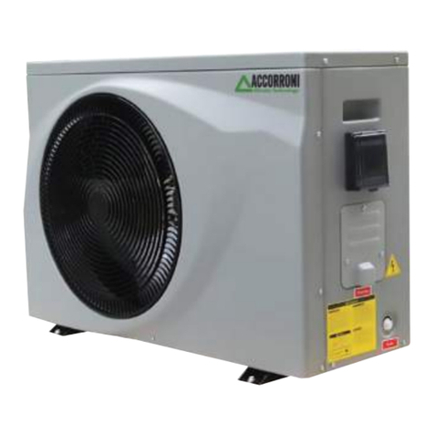
1) External motion-evaporator with electronic control defined
as: "Split water air mono bloc heat pump", powered
via R410A refrigerant with compressor ON - OFF
model Booster HR 7.8 (HUB RADIATOR PACK CF 8.0) or HR
3.0 (HUB RADIATOR PACK CF 3.0).
2) Internal unit composed of a condensing boiler
modulating from 2.9 to 24.9 kW that works to support the pump
of heat and a 48-liter accumulator of technical water in a vessel
closed inside which all the exchangers are positioned
in copper both for the production of ACS and for heat exchange
with the external evaporator.
1.2 CERTIFICATIONS - CE MARKING
The patented HUB RADIATOR PACK CF system complies with
the
Directives 97/23 / EC and 98/37 / EEC.
They also comply with the provisions of the following
Directives: 73/23 / EEC, 89/336 / EEC, as amended by
Directive 93/68 / EEC.
The internal unit of the HUB RADIATOR PACK CF hybrid
system
has been designed to be installed only and exclusively
inside buildings or on a special insulated outdoor niche
thermally and protected from atmospheric agents, if not
this indication is respected, no warranty whatsoever
warranty.
1.3 CONSTRUCTION CHARACTERISTICS
All machines are equipped with a microprocessor for
the control and regulations of operation and safety of the
unit.
The products of the HUB RADIATOR PACK CF series thanks to
the patented direct exchange capacitors can reach
high standards of energy efficiency and SCOP.
Other construction features:
- the cover for the outdoor unit is designed for everyone
the models in epoxy powder coated sheet.
The compressor compartment is completely isolated from the
compartment air cooler exchanger; this allows you to protect
against better electromechanical components;
- the compressor is of the high efficiency rotary type,
working with R 410A refrigerant, mounted on supports
anti-vibration rubber bands, operated by a single-phase electric
motor for all models;
- the air / refrigerant gas exchanger
it is made with copper pipes and blocked aluminium fins
by mechanical expansion of the tubes, with high
heat exchange surface;
- the fan unit consists of a helical fan
operated directly by single-phase asynchronous motor with
internal thermal protection. The fan is equipped with safety
protection grid;
- the A.C.S. quick exchanger it is made of copper
directly immersed in the technical water of the indoor unit
with the FIRST IN - FIRST OUT method, so as to eliminate the
Legionella problem inside the accumulation.
- the refrigeration circuit and the connections between the
individuals components are made of specific copper tube for
refrigeration. The organ of is part of the refrigeration circuit
lamination, the reversing valve cycle the separator of
liquid;
- the electric command and control panel is directly
positioned inside the cover cabinet.
- the microprocessor control system with keyboard is
located on the control plate directly accessible on the
front of the cover cabinet, and can be
remoted using the appropriate command and control panel
remote, available as an accessory, to be installed at
wall or recessed.
- the indoor unit is supplied complete with all the appropriate ones
internal copper exchangers, R410A refrigerant gas connections,
DHW connections, air vent valve, safety valve, filling tap, pressure
gauge, electronic circulator, 9 expansion vessel, temperature
probes, water tap drain.
1.4 CONTENT OF THE PACKAGING
The appliance is shipped on a wooden pallet, with protections in
extruded polystyrene foam and wrapped in a layer of fabric plastic
with air bubbles.
The identification data of the appliance are shown both on the
label on the packaging that on the inside of the technical data
plate of the cover cabinet. Do not remove the technical data plate,
as the references contained therein are necessary for any
maintenance operations. Inside the packaging there is also an
envelope containing this manual and the guarantee certificate,
which must be delivered to the owner of the appliance so that
store them carefully for any future use or consultation.
1.5 STANDARD EQUIPMENT AND ACCESSORIES PROVIDED
A REQUEST
The extensive standard equipment and accessories available on
request allow the optimal use of all the functions of the machines
and the plant to which they are subjected.
1.6 FIELD OF USE
Equipment designed and manufactured for heating of water in
hydronic air conditioning systems and to produce A.C.S., must be
used solely for this purpose, in report to their technical
specifications and performance. The quality and dimensions of
the materials used guarantee a good life span and are suitable for
the operation of the appliances both as a whole and in their
individual components, under reserve of an installation realized to
rule of art and in mechanical, chemical and thermal stress
conditions corresponding to a suitable use.
WARNING! All uses not expressly indicated in this manual they
are considered improper and are not allowed; in particular the use
is not foreseen of appliances in industrial processes and / or
installation in environments with a corrosive or explosive
atmosphere. The manufacturer declines all responsibility for
damages to persons, animals or things resulting from non-
compliance of the instructions in this manual, from modifications
or product tampering, from installation errors, of adjustment,
maintenance and improper use. Failure to comply with what is
indicated in this manual it also entails forfeiture of the warranty
conditions.
1.7 SAFETY STANDARDS
WARNING! Installation and maintenance must be carried out
exclusively by specialized personnel and specially enabled. The
connection to the power supply must be performed according to
the current national plant standards. During installation and
maintenance operations, it is always necessary to operate in the
maximum conditions safety, follow the instructions in this manual
and any warning labels applied on the product. Respect the
installation and operation limits indicated in in this manual, never
modify the wiring internal electrical and refrigeration pipes, do not
modify or disable the safety and adjustment devices. Before any
inspection, maintenance, or any other means access to internal
parts the appliance, remove the general power supply. In case of
need or clarifications for the installation and the maintenance
contact a Service Center directly Technique authorized by A2B
ACCORRONI E.G.

6
2. U.E. CONNECTIONS / IU
2.1 GENERAL PROVISIONS
1) The HUB RADIATOR PACK CF system is designed for
to work exclusively with the indoor unit positioned inside
of the building to be heated and the booster outside the building
2.2 ELECTRICAL CONNECTIONS
Connect the cable to the electrical panel:
1) The connection cable of the indoor and outdoor unit must
be of the H07RN-F type.
2.3 INSTALLATION OF PIPES FOR THE R410A
REFRIGERANT
The main cause of refrigerant gas leaks is due
to a defect in the flaring. Make folders so
corrected respecting the following indications:
A) Cut the pipes and the cable (Fig. 1)
- Use pipes with measurements suitable for the unit installed, ie
3/8 ’’ - 5/8 ’’ for Booster HR 7.8 and 3/8 ”- 1/4” for Booster HR
3.0.
- Measure the distance between the indoor and outdoor unit.
- Cut the pipes to a length slightly greater than the measured
distance.
- Cut the electric cable 1.5 mt. longer than length of the tube.
B) Burr removal (Fig. 2)
- Completely remove all burrs from the section transverse of the
tube.
- The processing must be carried out with the end of the tube
downwards so that the burrs do not fall into the tube.
C) Flaring (Fig. 3)
Remove the nuts fixed on the internal and external unit, insert
them on the pipe and carry out the banding and removal of
burrs, such as previously indicated.
D) Placement of the nut Fix the copper pipe firmly with a nut of
the size indicated in table 2.
E) Fixing the connection (Fig. 4)
Align the tubes. Tighten the nut sufficiently and tighten it with
two keys as shown in the figure.
- Precautions Excessive torque can break the nut, respect
then the details reported in table 2.
Table 1 - Specifications Cables HUB RADIATOR PACK CF
ModelsCable Cable magneto thermal STB
Connection cable power supply
QE indoor unit
Connection cable supply
external unit C-1-2 Pb3 - STB
Section Section Section Section Type
HR 3.0 2,5 mm2x 3 2,5 mm2x 3 1.50 mm2x 3
2 x (0,75 mm 2 x 2)
10 A curv. D
HR 7.8 4.0 mm2x 3 4.0 mm2x 3 1.50 mm2x 3
2 x (0,75 mm 2 x 2)
20 A curv. D
Table 2 - Tightening torque
Diameter Torque Tightening min - max (N / m)
Ø 1/4 14 - 18
Ø 3/8 33 - 42
Ø 5/8 63 - 77
Table 3 - Refrigerant charge
Models Dislivel H Pipe length (m)
Max (m) Max
Maximum length
without refrigerant
addict
Add refrigerant
quantity (g/m)
HR 3.0 5 15 5 20
HR 7.8 5 15 5 20
2) During the installation phase it must be checked carefully
that the distance and the difference in height between the 2
units are in accordance with the data shown in table 3.
3) Before installation, check that the wall where you are
chosen to position the internal storage is able to
to hold the weight itself and the water contained in it
of exercise.
4) In case of replacement of an existing generator, carry out the
chemical washing of the plant and adding a special one
anti-algae additive.
5) When choosing to install the hybrid system
HUB RADIATOR PACK CF, is to be taken into consideration
the electrical absorption of the outdoor unit. Then set up
all the works necessary to adapt the electrical system
(meter, cable section, circuit breakers, etc,) to guarantee correct
operation and voltage constant between 220 and 240 V.
6) Check that any existing exhaust ducts have an adequate
draft, do not present bottlenecks e that do not create dangerous
situations. The type of fume evacuation must be of the approved
type in the phase of certification, as described in the
identification plate of the product. You must also check that in
the fireplace or no other exhausts are inserted in the flue
appliances, unless it is made expressly to serve more users in
compliance with legal requirements.
7) Check that the appliance is set up to work
with suitable fuel, as indicated on the plate e
packaging.
2) Turn the electrical panel to the right and remove the screws,
then remove the cover.
3) Connect the cables according to the markings.
Connect the cable to the external unit.
4) Remove the cover of the outdoor unit.
5) Connect the terminal cables according to the numbers on the
unit terminal board, respecting the sections shown in
table 1
6) Fix the cables so that they do not come in contact with parts
electric or metal

7
PIPE CONNECTIONS
(CUT)
Fig. 1
PIPE CONNECTIONS
(FLARING)
Fig. 3
PIPE CONNECTIONS
(BURR REMOVAL)
Fig. 2
PIPE CONNECTIONS
(FIXING)
Fig. 4
3. OUTDOOR UNIT INSTALLATION
3.1 GENERAL INDICATIONS
When choosing the installation position, respect carefully the
following indications:
Fig. 5
-Make sure that the difference between the INTERNAL UNIT
and the UNIT OUTSIDE is not greater than 5.0 m.
- The appliance must be installed so that the influences of
adjacent structures and / or the effects of climatic conditions
details (snow, wind, etc. ...) do not compromise the product
operation and / or personal safety e of assets.
- Make sure that the space at the back of the unit is greater than
30 cm. The front must have more than 60 cm. of space.
- Ensure that there are no obstacles to free movement of air
through heat exchangers: A) do not dispose plants or animals
directly close to the air flow;
B) avoid installation in corners where it is usually deposited
dust, leaves and anything else that can reduce efficiency
of the exchangers obstructing the passage of air (Fig 5).
- Position the air discharge so that the flow is not hampered in
any way. In the case of strong winds, make sure the fan works
correctly, positioning the unit longitudinally, along a wall or using
one shielding

3.2 DISTANCES OF RESPECT (Fig. 7)
Respect the minimum spaces, so as to allow the correct
operation and all installation operations e maintenance.
3.3 ROOF INSTALLATION
- If the outdoor unit is installed on a roof, make sure of
level the unit. Make sure the roof structure is appropriate for
mounting the unit.
- Consult the local codes regarding the assembly on the
roof.
- If the outdoor unit is installed on the roof or on the external
walls, this could cause excessive noise and vibrations and
be classified as an unsuitable service installation.
3.4 ELIMINATION OF AIR WITH THE VACUUM PUMP
(Fig 8)
Air and moisture in the refrigerant system can cause effects
unwanted as shown below:
- Increased pressure in the system.
- Increased current consumption.
- Decreased refrigerant efficiency.
- Freezing and obstruction of the capillary pipes.
- Corrosion of the parts of the refrigeration system
- If the appliance must be suspended from a wall external, the
support must comply with the technical specifications.
The wall where the unit is to be installed must be in bricks or
material of similar consistency, otherwise it must be reinforced.
The support brackets must be stable, resistant and with an
adequate degree of protection against corrosion.
WARNING! Make sure of the bearing capacity of the part
on which the shelves and the anchoring system are placed
to the wall itself, depending on the weight of the appliance
to install.
- Do not install the appliance near sources of heat and / or
areas with fire hazards.
- Installation in areas with highly corrosive atmosphere
it is not allowed; in particular climatic conditions as in
near the sea, it is mandatory to provide for a duration of
lower life of the product and in any case a more frequent and
accurate maintenance.
- In the outdoor unit, from which the water from is eliminated
condensate, provide a suitable drainage and / or
channelling of the same, so as to avoid situations of
danger due for example to ice formation on
transit areas.
- The outdoor unit is designed to be installed outdoors and
it does not need a special base, however it must
be securely positioned on a support surface
horizontal of adequate bearing capacity and equipped with
special ones anti-vibration pads (Fig 6).
To avoid the above, the internal assembly and the tubes, placed
between internal and external group, must be tested for leaks
and purged to remove non-condensing elements and moisture
from the system. Check that each tube, (both the gas side tubes
and the liquid) between internal group and external group, has
been connected in the correct way and that all the wiring
necessary for the testing have been carried out. Remove the
valve cap on the outdoor unit. Make sure at this point that both
the gas valves are on liquid remain closed. Check the length of
the pipe and relative quantity of the refrigerant, for a correct
charge, check the superheat value. At the table values are
indicative. When changing places to the unit, perform the purge
with the vacuum pump. Make sure that the refrigerant inside the
conditioner is always in liquid state. The outdoor unit is supplied
with a charge of refrigerant gas R410A suitable for guaranteeing
correct operation up to one maximum distance of 5 meters from
the indoor unit. If you decide to install the 2 units at a greater
distance of 5 meters, make sure to add 20 g of refrigerant gas
per every meter more than piping (Tab. 3). For example, if there
are 7 meters of indoor and outdoor units add 40 g of R410A gas
to the pipe. In any case, never exceed 15 meters. Perform the
addition only after having carried out the vacuum in the pipes
that connect the 2 units, after which you can proceed with the
opening of the gas taps, mounted on the machine. 3.5
EVACUATION Connect the end of the charging hose to the
pump of the vacuum to evacuate the air from the pipes of the
indoor unit. Check that the "LO" knob on the pressure gauge
valve be open. Then run the vacuum pump. The time of
operation varies depending on the length of the pipes and the
pump capacity. When the desired vacuum is reached, close the
knob "LO" of the pressure gauge valve and stop the vacuum
pump. In conclusion, using a service valve wrench, rotate the
stem of the gas side valve counter clockwise to open it
completely. Loosen the flexible charge hose connected to the
service socket of the gas side to release the pressure, then
remove the tube. Replace the gas valve and nut cover service
and tighten well with an adjustable wrench. This procedure is
very important to avoid losses Plant Replace the service valve
caps on both the gas and fuel side from the liquid one and
tighten well. This completes the air purge procedure with the
pump of the vacuum, make sure that all the pipes are connected
in a manner correct and that the service valves of the gas and
liquid sides are completely open.
3.6 PUMP DOWN
This procedure is performed when the group must be moved or
assistance is provided to the refrigerant circuit. Emptying allows
you to collect all the refrigerant in the external group without
losses occurring.
Fig. 6
8

9
Fig. 7
Fig. 8
WARNING! To make sure
to perform the procedure of
emptying with the group
in COLD MODE
3.7 RECOVERY PROCEDURE
- Connect a low pressure gauge with a hose to the
service port of the gas valve.
- Open the gas valve in half and empty the air from the
piping of the pressure gauge using the refrigerant gas.
- Completely close the liquid valve.
- Turn on the machine in cooling mode.
- When the pressure of the pressure gauge goes from 0
to 0.5 kg 2G cm (between 14.2 and 7.1 P.S.G.I)
completely close the gas valve and quickly switch off the
air conditioner.
The complete recovery of the refrigerant was thus carried
out of the external unit
Indicator of
pressure
pressure
gauge valve
Open Close
Cylinder gas
R410A
Electronic
Scale
Vacuum pump

10
4. INSTALLATION OF INDOOR UNITS
7
8
11 10
5
15
12 14
3
4
6
9 18
16 17
13
19
2
Always install the accumulator inside the building to be heated
away from atmospheric agents and inside a room a
controlled temperature.
Make sure the wall on which the indoor unit will be installed
able to support the entire weight of the system.
Below are the main components that make up the internal unit.
Main components:
1 Support condensing boiler
2 Electronic command and control panel
3 WILO YONOS PICO 25 / 1-8 circulator
4 Digital electronic control unit heat pump
5 Methane gas inlet
6 Digital electronic boiler control unit
7 Boiler smoke outlet
8 60 liter technical inertial storage tank
9 Support bracket
10 3/4 ”system return
11 DHW delivery 1/2 "
12 Cold water inlet 1/2 "
13 3/4 ”system delivery
14 Filler cock
15 Wild air vent valve
16 ON - OFF boiler switch
17 SUMMER / WINTER switch
18 R410A 3/8 ”gas connection
19 Gas connection R410A 5/8 "
4.1 CHOICE OF INSTALLATION SITE OF THE HYBRID
SYSTEM
When determining where to install the internal unit of the system
hybrid HUB RADIATOR PACK CF take the following into
account:
- of the indications contained in paragraph 4.5 (System of
air intake / fume exhaust);
- check that the wall structure is suitable to support the
weight of the indoor unit in operation, avoiding the fixing on
inconspicuous partitions;
- avoid placing the indoor unit above a
appliance that, during use, can affect in
somehow the proper functioning of the same (kitchens
which give rise to the formation of fatty vapours, washing
machines,
shower compartments or bathtubs, etc.).
For correct positioning of the HUB RADIATOR PACK CF
it is necessary to follow the instructions given in Fig. 10 A and
10 B to prepare the connection pipes to the system
heating, sanitary water, gas network and
air intake / flue gas pipes at the time of
hydraulic installation and before installation
of the internal unit HUB RADIATOR PACK CF.
Fig. 9
M RCFG
Fig. 10 B
1
Fig. 10 A
32
45
32
45
62 87 70 24418572

11
1
319
7
97 7
7
7
7
7
7
14
7
7
7
7
7
11
21
20
13
12 8
14
7
7
10
78
16
17
15
1818 18 88
8
620
7
7
4
5
2
4.3 EXAMPLE OF HEATING SYSTEM AND PRODUCTION OF DHW WITH PATENTED HUB RADIATOR PACK CF SYSTEM
6 Polyphosphate dispenser
7 Ball valve
8 Check valve
9 Magnetic dirt separator
10 DHW mixing valve
11 Water meter
12 Pressure reducer
13 Water softener
14 Collection tap
15 Sand trap filter
16 Water network disconnector
17 Pressure gauge
18 Utilities DHW
19 Méthane gas cock
20 Y filter
21 General water supply inlet
A) Position the wall fixing bracket on the wall where it is
wants to install the internal unit.
Make sure the bracket is perfectly with a level horizontal and
that the support surface is regular.
Use the bracket as a template and mark the position of the holes
from to achieve.
x 3
Wilo Yonos Pico 25/18
60
4,5
7,5
4-75
4
6
3/4”
3/4”
1/2”
1/2”
230V/1/50Hz
1447
720
307
146
4.2 TECHNICAL DATA INTERNAL UNIT PATENTED HUB RADIATOR PACK CF
Model
Electronic Circulator Type
Water accumulation content
Max electronic circulator capacity
Max electronic pump head
Electronic circulator electric absorption
TSafety valve calibration
Expansion vessel volume
System connection fittings
Natural gas / LPG connection fittings
ACS connection fittings
Water inlet connection connections
Liquid connection R410A
Gas connection R410A
Power supply
Height
Width
Depth
Weight in operation
PACK CF 3.0
1/4”
3/8”
PACK CF 8.0
3/8”
5/8”
U.M.
l
m3/h
m
W
bar
l
mm
mm
mm
Kg
1 Support boiler
2 60/100 coaxial drain
3 Natural gas inlet
4 System delivery
5 System return
4.4 ASSEMBLY PROCEDURE

12
I) Make the electrical connections between the electrical panel
and the main power supply and between the electrical panel and
the terminal block located on the right side of the outdoor unit
following the indications reported in table 1.
Prepare a dedicated electric line that starts directly from the
counter to bring the main power supply to the electrical panel
located inside the covering mantle of the internal unit.
This line must be equipped with a suitable magneto thermal
protection placed upstream and must be of a section to avoid a
voltage drop higher than 2.5 V
G) Proceed with the connection of the flow and return
of the heating system using 3/4 ”fittings
WARNING! the circulator mounted on the machine
is able to supply the nominal water flow with the
prevalence indicated in the technical data table. To verify
that the load losses do not exceed the prevalence
helpful available.
However, it is recommended to comply with the requirements
below reported:
- the diameter of the pipe of the sampling line from the network
must not never be less than the attack of the machine;
- properly fix the pipes, the weight of which must not
burden on the appliance;
- properly insulate the pipes to find the right ones
heat losses.
H) Connect a special safety drain in correspondence
of the 1/2 ”female threaded connection of the safety valve.
F) Once the indoor unit has been positioned, proceed with the
connection to the heating system using the pipes
below indicated to which you must apply 2 fittings to tighten
3/4 ”content inside the transparent packaging.
B) Once the position of the fasteners has been marked, make a
appropriate holes for inserting wall plugs to choose based on the
weight of the indoor unit in operation and according to the
structural type of the wall.
C) Insert the fixing bracket again and tighten with the screws
on the wall, chosen on the basis of the indications given in point B.
D) Hook the indoor unit without cover cabinet to the bracket
just fixed to the wall by positioning the "L" bracket already fixed
to the structure of the indoor unit (see figure below).
E) Firmly lock the indoor unit to the wall behind it
with 2 wall plugs to be applied on the 2 holes in the uprights
vertical (see figure below).
x 2
Flow Plant
Return
Plant
entrance
methane gas
entrance
DHW
Flow
DHW
Water network
exhaust
valve
safety
evacuation
condensate
boiler
faucet of
emptying
pressure gauge
faucet of
filling

13
WARNING! all electrical connections must be
performed by qualified personnel and the electrical system must
comply with all applicable regulations
L) Proceed with the refrigeration connections following all the
instructions given in section 2.3 of this manual. In
shape the pipes avoid any type of squashing and
make sure that each portion of the pipe is perfectly
thermally insulated from beginning to end.
WARNING! complies with all applicable regulations.
All refrigeration connections must be carried out by
qualified personnel with F-GAS certification
(Presidential Decree January 27, 2012, No. 43)
M) Once all the connections have been made, request the
internal unit
with the special cover cabinet that must be placed first
from top to bottom on the wall mounting bracket and then done
rotate towards the wall until hooking on the appropriate pins a
disappearance, placed on the lower fixing plate.
4.5 FLUE / AIR DISCHARGE OPENING SYSTEM
In the internal unit of the HUB RADIATOR PACK hybrid system
CF is a highly efficient condensing boiler
Modulating.
Regarding the discharge of fumes into the atmosphere and the
systems of
air intake / fume exhaust comply with laws and regulations
in force, which here are intended as fully transcribed.
Safety devices are installed on the boiler for the boiler
control of the evacuation of combustion products.
exhaust fumes the devices put the boiler in safety and on the
LCD display shows the flashing code E14. It is absolutely
forbidden to tamper with and / or exclude them safety devices.
In the event of repeated shutdowns of the boiler it is necessary
have the air intake / flue gas exhaust ducts checked, which
may be blocked or inadequate for the disposal of fumes in the
atmosphere. For the air intake / flue gas exhaust, the following
must be used ducts and specific systems for original condensing
boilers, resistant to the attack of condensation acids.
The exhaust pipes must be installed with one slope towards the
boiler to guarantee the reflux of the boiler condenses towards
the combustion chamber that is built for collect and discharge
the condensate.
If this is not possible it is necessary to install, in condensation
stagnation points, systems capable of collect and convey the
condensate to the exhaust system of the condensation.
Condensation stagnation points in the system must be avoided
evacuation of combustion products, with the exception of of
liquid of the eventual siphon connected to the system of
evacuation of combustion products.
The manufacturer declines all responsibility for damage caused
to following errors in installation, use, transformation
of the appliance or failure to comply with the instructions
provided by the manufacturer or the current installation
regulations concerning the material in question.
In case of malfunction of the intake system a
Terminal
Gas line connection
Liquid line connection R410A
Liquid tap
Gas line connection
Gas line connection
External booster Internal unit
For wall positioning of the exhaust terminals of the boiler, in the
cases prescribed by DPR n.551 dated 12/29/99, follow at the
distances indicated in the table and in the figure below.
Air aspiration Fume exhaust Condensate Rain

14
Note:
POSITIONING OF TERMINALS FOR "FORCED DRAFT" APPLIANCES (extracted from the UNI 7129 standard)
Under window A 600
Under ventilation opening B 600
Under gutter C 300
Below balcony (1) D 300
From an adjacent window E 400
From an adjacent ventilation opening F 600
From vertical or horizontal pipes or drains (2) G 300
From the corner of the building H 300
From a recess of the building I 300
From the ground or from another walking surface L 2200
Between two vertical terminals M 1500
Between two terminals in horizontal N 1000
From a front surface facing without openings or terminals within a radius of 3 meters from the outlet of the fumes O 2000
The same, but with openings or terminals within a radius of 3 meters from the outlet P 3000
Position of the unit
Distance
min
in mm
Units heating power
16 - 35 kW
Type C53
Boiler with combustion air intake ducts and evacuation of
separate combustion products. These ducts can discharge in
different pressure areas. The positioning of the two terminals on
walls is not permitted opposing. The boiler must be equipped with
a fan upstream of the combustion chamber / heat exchanger.
Type C63
Boiler with combustion air intake ducts and evacuation of the
feasible combustion products using separately marketed and
certified tubes. The realized system must not have a loss of load,
with boiler with nominal power, higher than the residual head of
the fan.
Type C83
Boiler designed to be connected to a terminal for the withdrawal
of combustion air and an individual chimney or collective for the
discharge of fumes. The flue must comply with current
regulations. The boiler must be equipped with a fan upstream of
the combustion chamber / heat exchanger.
DIAMETER COAXIALS 100/60 MM
Type C13
These values refer to air intake / exhaust ducts
fumes made using rigid and smooth pipes
originals, supplied by the manufacturer.
The maximum allowed length of horizontal coaxial pipes
100/60 mm is 7 meters including the first corner.
For each rectilinear pipe added with a length of 1 meter the maximum
allowed length must be decreased by 1 meter.
(1) The terminals under a workable balcony must be placed
in such a position that the total path of the fumes, from the exit point
of the same from the terminal to their outlet from the external
perimeter
of the balcony, including the height of the eventual balustrade of
protection, not less than 2000 mm.
(2) In the placement of the terminals must be adopted
distances not less than 500 mm from action sensitive materials
of combustion products (for example, gutters and downspouts in
plastic material, lumber in wood, etc.) unless adopted
adequate shielding measures with respect to these materials.
4.6 CONFIGURATION OF AIR SUCTION DUCTS /
FUME EXHAUST TYPE B23
Boiler designed to be connected to a flue or a device for discharging
the products of combustion outside of the room in which it is installed.
The air is drawn in the installation room and unloaded of the
combustion products takes place outside the room same.
The boiler must not be equipped with a draft diverter
windproof, while it must be equipped with a fan upstream of the
combustion chamber / heat exchanger.
Type C13
Boiler designed to be connected to horizontal terminals of
exhaust and intake directed to the outside through type ducts
coaxial or by means of split type ducts.
The distance between the air inlet duct and the outlet duct
fumes must be at least 250 mm and both terminals
they must still be placed inside a square
of 500 mm on the side.
The boiler must be equipped with a fan upstream of the
combustion chamber / heat exchanger.
Type C33
Boiler designed to be connected to vertical terminals of
exhaust and intake directed to the outside through type ducts
coaxial or by means of split type ducts.
The distance between the air inlet duct and the outlet duct fumes
must be at least 250 mm and both terminals they must still be placed
inside a square of 500 mm on the side.
The boiler must be equipped with a fan upstream of the combustion
chamber / heat exchanger.
Type C43
Boiler designed to be connected to a system of collective chimneys
including two ducts, one for the suction of the combustion air and the
other for the evacuation of the combustion products, coaxial or
through ducts split.
The flue must comply with current regulations.
The boiler must be equipped with a fan upstream of the combustion
chamber / heat exchanger

15
For each 90 ° bend added the maximum allowed length must be
decreased by 1.5 meters. For each 45 ° bend added the maximum
allowed length must be decreased by 1 meter.
The wall terminal decreases the maximum allowed length of 1.5
meters. The air intake part must have a slope down 1% in the exit
direction, to avoid entry of rainwater.
Type C33
The minimum allowed length of vertical coaxial pipes is 1
meter. The maximum allowed length of vertical coaxial pipes
100/60 mm is 7 meters.
For each rectilinear tube added 1 meter long
maximum allowed length must be decreased by 1 meter.
For each 90 ° bend added the maximum allowed length must
be reduced by 1.5 meters.
For each 45 ° bend added the maximum allowed length must
be reduced by 1 meter.
Roof unloading reduces the maximum permitted length by 1.5
meters.
4.6.2 SWEEPER FUNCTION
The boiler has the chimney sweep function which must be
used for on-site measurement of combustion efficiency and for
enter the subsequent combustion regulation phase.
To activate the chimney sweep function it is necessary to hold down,
for the cycle time, the "MODE + RESET" keys.
Parameter Set Value Default Value
Note
P46
Modulating speed selection of the pump
0 - 1 1
0 = not modulated
1 = automatic 60% ÷ 100%
P47
Selection
ΔT for pump modulation (°C)
10 ÷ 40 20
P48
Pump operation selection
0 - 1 0
0 = intermittent
1 = continuous
P49
Enable OEM
0 ÷ 99 0
49 = allows reading / writing of the following parameters
P50
Not used
P51
Not used
P52
Automatic fill selection water
0 - 1 0
0 = not present
1 = present
Don't modify this value
P53
Not used
P54
Automatic water filling selection Automatic water
filling selection
10 ÷ 40 (lx10)/min 15 (1,5l/min)
P55
DHW post-purge time selection
1 ÷ 30 sec x 10 3
P56
DHW post-circulation time selection
0 ÷ 100 sec 30
P57
Selection of fan speed increase
0 ÷ 10% 0
DO NOT MODIFY THIS VALUE
P58
Not used
P59
Not used
P60
Offset aggiuntivo alla temperatura di
spegnimento dopo accensione bruciatore
0 ÷ 20 0
DO NOT MODIFY THIS VALUE
P61
Selezione allarme temperatura scarico fumi
20 ÷ 150 105
P62
Not used
P63
Not used
P64
Not used
P65
Anti-legionella duration selection
5 ÷ 30 min 15 min
Only for kettle with thermostat
P66
Not used
P67
Not used
P68
DO NOT MODIFY THIS VALUE - Not used
P69
DO NOT MODIFY THIS VALUE - Not used
P80
Selection
ΔT heating for detection
circulation block
0 ÷ 20 5
0 = disabled
P81 Maximum heating temperature
0 ÷ 150 90
0 = disabled
P82
Selection
ΔT maximum flow / return
acceptable
0 ÷ 50 30
0 = disabled - Do not modify
P83
Selection of months missing from maintenance
0 ÷ 255 0
0 = disabled
P98
Reset TSP to factory values
0 - 1 0
P99
OEM reset to factory values
0 - 1 0
Tabella 10 - Tabella generale parametri TSP
4.6.4
Parameter Settable values Default values Notes
If the keys are released before the end of the cycle time, the
boiler continues to operate normally.
If a sanitary request is present, the chimney sweep function comes
performed on the sanitary, otherwise in heating.
Entering the chimney sweep function, the display shows "Lo" letters
alternating with the water temperature value of heating (ex. 45),
indicating the entry in the activation of the "Chimney sweep function"
at minimum power. The display shows the symbol "" if the burner is
on. The boiler executes the sequence ignition and then switch to
power minimum ("Lo").
Press the "flame" button for 3 seconds to switch to the "function
chimney sweep "at maximum power (" Hi ").
Keep the button pressed for 3 seconds to return to the "function
chimney sweep "at minimum power (" Lo ").
To exit the chimney sweep function press and hold for 3 seconds
the "RESET" button and return to normal operation.
The duration of the chimney sweep function is 15 minutes.
4.6.3 CONNECTION TO THE GAS NETWORK
The gas supply pipe must have the same section
or higher than that used in the boiler.
The section of the pipe depends on its length, on the type of pipe
route and gas flow. It should therefore be sized.
Follow the current installation regulations that are intended here
fully transcribed.

16
Parameter
Valori impostabili Valori di default Note
P01
Boiler type selection
0 ÷ 8 0
0 = instantaneous
1 = with kettle thermostat
2 = with kettle temperature probe
3 = heating only
P02
Gas type selection
0 - 1 0
0 = natural gas
1 = LPG
P03
Selection type DHW control
0 - 1 1
0 = flow switch
1 = flow meter
P04
Regulation coefficient with external probe
0 ÷ 90 30
P05 Anti Fast Cycles time
0 ÷ 10 min 3
P06 1
DO NOT MODIFY
P07 Ignition Heating ramp [value 1=10s]
0 ÷ 80 12
P08
Maximum heating power selection
(PREMIX) P10...100 70%
P09
Selection of maximum DHW power
P10…100 80%
P10
Minimum power selection
0…P09 0%
P11
Minimum setpoint value selection
heating
20...P12 25°C
P12
Selection of the maximum setpoint value
heating
P11…80 80°C
P13
Selection of the maximum value of the DHW setpoint
35 ÷ 67 60°C
P14
Selection of calibration type
0 ÷ 20 0 0 = manu
5 = auto
P15
Boiler power selection
0 ÷ 4 4
0 = 24 kW
1 = 28 kW
2 = 32 kW
3 = 16 kW
4 = 20 kW
P16
Not used
P17
Not used
P18
Not used
P19 Thermostat (0) / Flue gas probe (1)
0 - 1 1
DO NOT MODIFY
P20
Selection of the minimum value of the DHW
35 ÷ 50 35
P21 Low temperature zone selection
0 - 1 0
0 = High temperature
1 = Low temperature
P22
Not used
P23 Selection of pump activation time
(min): cold area
0 ÷ 10 0
P24
Child protection
0 ÷ 1 0
1 = active protection
P25
Not used
P26 Ram stroke delay selection (sec)
0 ÷ 3 0
P27 Preheating temperature selection OFF (°C)
30 ÷ 75 45
P30
Not used
P31 Fan speed selection
(P31 x 25) rpm 80 ÷ 160 140
P32 Fan max speed selection (P32 x
25) + 2000) rpm P33...255 170
P33 Fan minimum speed selection (P33 x 25)
30 ÷ 60 36
P36
Not used
P37 AUX probe
3 ÷ 3 3
DO NOT MODIFY
P38 Antifreeze temperature selection
0…+10 5
P39
Post-circulation heating time selection
0 ÷ 99 sec x 10 120
P40
Ignition delay time selection heating
0 ÷ 60 sec x 5 0
P41
Sanitary modulation selection with flow meter
0 ÷ 1 1
0 = not active
1 = active
P42
Select enable / disable preheating function
ACS
0 ÷ 1 0
0 = disabled
1 = enabled
P43
DHW activation delay time selection with
solar configuration
0 ÷ 30 sec 0
P44
Selection of pressure sensor type
0 - 1 1
0 = pressure switch
1 = trasducer
P45
Anti-legionella function selection (cylinder only)
54, 55 ÷ 80 54
54 = disabled
55 ÷ 80 = delivery temperature set

17
4.7 ADAPTATION TO USE OF OTHER GASES AND BURNER REGULATION
The boilers are produced for the type of gas specifically
requested when ordering, which is shown on packing plate
and on the boiler technical data plate.
Any subsequent transformations must be carried out
strictly by qualified personnel, who will use the
appropriately prepared accessories by the manufacturer
and will carry out the modification operations and the
adjustments needed for good tuning.
4.7.1. TRANSFORMATIONS FROM METHANE TO LPG
Change parameter P02 from 0 to 1.
Place the LPG adjustment label on the boiler.
Check and if necessary modify the parameters P08, P09, P31,
P32 and P33 according to what is indicated in the table of
parameters.
PARAMETER ACCESS
Simultaneously pressing, for the cycle time, the keys "RESET"
and " " You enter the parameter programming mode. The
display shows "tS" for 1 sec, then the P number of TSP for 1 sec
and then the value for 3 sec. The first modifiable parameter
corresponds to P01. Press the or button to select the
desired parameter. Pressing, for the cycle time, the key
enables the function of modification of the selected parameter.
The previously set value appears on the display. Pressing the
or keys changes the value of the parameter selected.
Pressing the " button for the cycle time saves the new one
setting. Simultaneously pressing, for the cycle time, the keys
"RESET"and Exits in parameter programming mode. Proceed
with combustion regulation (CO2).
4.7.2. GAS TO METHANE TRANSFORMATIONS
Change parameter P02 from 1 to 0. Place the label indicating the
adjustment on the boiler a Methane.Check and if necessary
modify the parameters P08, P09, P31, P32 and P33 in
accordance with Table 24.
PARAMETER ACCESS
Simultaneously pressing, for the cycle time, the keys "RESET"
and "" You enter the parameter programming mode. The display
shows "tS" for 1 sec, then the P number of TSP for 1 sec and
then the value for 3 sec. The first modifiable parameter
corresponds to P01. Press the "" or "" button if the desired
parameter is selected. Pressing, for the cycle time, the "" key
enables the function of modification of the selected parameter.
The previously set value appears on the display. Pressing the ""
or "" keys changes the value of the parameter selected. Pressing
the "" button for the cycle time saves the new one setting.
Simultaneously pressing, for the cycle time, the "RESET" keys
and "" you exit the parameter programming mode. Proceed with
combustion regulation (CO2).
4.7.3. CHECK AND ADJUSTMENT OF THE GAS VALVE
PREMISE The boiler, by means of the "BEST" function, is
suitable automatically combustion according to the conditions of
installation, therefore the following procedure is to be carried out
following the chimney sweep function if the calibration values gas
were not corresponding to those on the plate or if yes the
electronic board, the electrode, the fan or the gas valve. The
boiler must be ready for operation, purged from the air and with
heating function enabled. The procedure can start in two different
ways depending on of the value of the parameter "P14": AUTO
("P14" = 5): the boiler performs 10 ignition attempts a powers
gradually increasing;
MANU (“P14” = 0): la caldaia esegue 5 tentativi di accensione
alla potenza di accensione indicata nel parametro “P31”.
Una volta ottenuta con successo l’accensione del bruciatore, la
caldaia esegue in autonomia un ciclo alla potenza minima “P0”,
di accensione “P1” e alla potenza massima “P2” per ottenere
una buona stabilità di amma, poi si porta in modalità di modica
della CO2 per permettere la taratura manuale.
L’impostazione del tipo di modalità (AUTO o MANU) viene
immessa nel codice di attivazione per il parametro “P14” nel
menù Parametri TSP.
Parametri TSP impostabili da interfaccia e da Comando Remoto.
La modalità AUTO è quella consigliata e che permette la più
ampia libertà di modica della CO2.
Mixer
Gas tube
Valvola gas
OPERATIONS TO BE PERFORMED
Enter the chimney sweep function and check that the value
of CO2 falls within the limits of Table 11 both at maximum (Hi)
that to the minimum (Lo) power (if the temperature of the plant
should it rise too high, it is possible to open the taps
ACS to dispose of the heat; the procedure cannot be started
with the ACS open).
If this is not the case, proceed as described below.
Press the "MODE" keys simultaneously for the cycle time
MODE
”
e “
RESET
”. Release then press immediately (within 2 seconds)
one time .
The card confirms the activation of the function and displays on
the "Au-to" or "Ma-nu" display depending on the mode defined
setting. The card will internally generate an operation request in
“calibration” mode and the ignition sequence will start. If the "Au-
to" function is active, the flashing is also activated of the
"radiator" symbol. Once the ignition has been completed, the
boiler will perform a parameter storage cycle at maximum
power, then to the ignition power and, finally, to the minimum
power. During this phase, the LCD display cyclically displays the
cycle time and delivery temperature. At this point the fumes
analyzer probe can be inserted into the exhaust duct.

18
A
4.7.4 BOILER TESTING
Each boiler is supplied with a control certificate.
The compilation of the certificate of inspection by a Authorized
Service Center allows you to enjoy the advantages offered
from the insurance formula provided by the second
manufacturer as specified in the inspection certificate itself.
4.7.5. PRELIMINARY CHECKS
Before testing the boiler it is advisable to check:
- the smoke evacuation duct and the terminal part are
installed according to the instructions: with the boiler on
no escape of products of the
combustion by no gasket;
- the boiler power supply voltage is 230 V - 50 Hz;
- the system is correctly filled with water (pressure at
pressure gauge 1-1.3 bar);
- any pipes interception cocks
of the system are open;
- the network gas corresponds to that of the boiler calibration:
otherwise, carry out the conversion
of the boiler to use the gas available: this operation
must be performed by qualified technical personnel;
- the fuel supply tap is open;
- there are no leaks of combustible gas;
- the general electric switch upstream of the boiler is
inserted;
- the 3 bar safety valve is not blocked;
- there are no water leaks;
- the condensate drain trap, mounted in the boiler,
properly drain the condensate and it is not blocked.
If the boiler is not installed properly to the laws and regulations
in force, notify the manager installation and do not test the
boiler.
4.7.6. MAINTENANCE
Maintenance (and repair) operations must be performed by
qualified personnel.
The manufacturer advises its customers to contact, for the
maintenance and repair operations, to the network of its own
Authorized Service Centers that are trained to perform
at best the aforementioned operations.
Proper boiler maintenance allows the same to
work in the best conditions, respecting the environment and in
full safety for people, animals and things.
Maintenance operations must be performed at least
once a year.
Before proceeding with any maintenance operation which
involves the replacement of components and / or of
cleaning the inside of the boiler disconnect the appliance from
the power supply network.
Maintenance operations include control operations and cleaning
as specified below;
Control operations:
- general check of the integrity of the boiler;
- check the tightness of the gas circuit of the boiler and the
gas supply network to the boiler;
- control of the boiler supply pressure;
- boiler ignition control;
- control of the combustion parameters of the boiler by
smoke analysis;
- integrity check, good state of conservation e
checking the operation of the combustion fan;
AUTO ADJUSTMENT
The message "P0" appears on the display and the card is ready for
set the value of O2 to the minimum power.
“ ” Is used to switch between the Power / O2 menu (for the
cycle time).
“ ” o “ ” are used to increase / decrease the value of the O2
or change the power of the system (if the symbol of flame
flashes).By pressing the keys "" or "" it will be possible to
modify the value current RFlame set and vary the O2. Press the
"" button (for the cycle time) to confirm adjustment to "P0" and
"" (for the cycle time) to go to second level to be adjusted "P1".
Proceed with the CO2 calibration following the steps taken for
adjust the minimum. Press the "" button to confirm and "" to
switch to adjustment of the maximum "P2". Adjust the value as
shown in the table. Confirm with the "" button. Press the
"MODE" button (without waiting for the cycle time) to finish the
procedure and memorize the adjustments made.
MENU ADJUSTMENT
The message "P0" and the card appear on the display. ready to
adjust the CO2 value at minimum power. With this condition:
"" Is used to switch between the Power / CO2 menu (for the
cycle time). Or are used to increase / decrease the value
of CO2 or change the power of the system (if the symbol of
flame flashes). Press the " " button for the cycle time to activate
the menu CO2. By pressing the keys or it will be possible
to modify the value RFlame current set and correct CO2. Press
the button (for the cycle time) to confirm adjustment to "P0"
and (for the cycle time) to go to second level to be adjusted
"P1". Proceed with the CO2 calibration following the steps taken
for adjust the minimum. Press the "" button to confirm and to
switch to adjustment of the maximum "P2". Adjust the value as
shown in the table, confirm with the "" button. Press the
"MODE" button (without waiting for the cycle time) to finish the
procedure and memorize the adjustments made. It is possible
to exit the function at any time adjustment by pressing the
"MODE" button for the cycle time. Finally set P08 at 70% and
P09 at 80%.

19
- check the integrity of the boiler safety devices in general;
- control of the absence of water leaks and absence of oxidation
of boiler fittings;
- check the efficiency of the safety valve implant;
- control of the expansion vessel charge;
- check for correct evacuation of condensate by of the
condensate
drain trap installed in the boiler.
Cleaning operations:
- general internal cleaning of the boiler;
- cleaning of gas nozzles;
- cleaning of the air intake and exhaust circuit fumes;
- cleaning the heat exchanger;
- cleaning the siphon and the condensate drain pipes.
If the boiler is checked for the first time, check:
- the declaration of conformity of the plant;
- the system booklet;
- the suitability of the room for installation;
- the smoke evacuation channels, diameters and length of the
same;
- the correct installation of the boiler according to the instructions
contained in this booklet. If the device is not able to power
function properly and in the absence of danger to people,
animals and things advise the plant manager and fill out a
statement to that effect.
4.7.7. COMBUSTION ANALYSIS
The control of the combustion parameters of the boiler for the
assessment of performance and pollutant emissions must
be performed in accordance with the laws and regulations in
force.
4.7.8. DEACTIVATION, DISASSEMBLY AND DISPOSAL
If you decide to permanently deactivate the boiler,
have the operations of deactivation, disassembly and
disposal only to qualified personnel.
The user does not. authorized to perform these personally
operations.
Deactivation, disassembly and disposal operations must
be performed with cold boiler, after having disconnected it from
the gas network and the electricity grid.
The materials of which the boiler is made are all recyclable.
Once dismantled, the boiler must be disposed of in compliance
of the legislation in force in the country of installation.
Technical incidents table
49
STATO DELLA CALDAIA INCONVENIENTE
E 02 The water pressure in the heating system is insufficient
E 03 System pressure too close to the maximum limit
E 04 Sanitary probe fault
E 05 Flow probe failure
E 14 Smoke probe fault
E 13 Fumes probe intervention
E 15 Fan failure (feedback / power supply)
E 06 + No ignition
E 07 + The safety thermostat has intervened
E 08 + Flame error
E 09 No water circulation in the system
E 16 Return probe failure
E 20 System over temperature
E 21 Delta T CH/Ret > TSP82 (1)
E 11 Gas valve modulator and disconnected
E 12 Boiler probe failure
E 19 Sanitary flow meter error
E 28 + Attempts to release from the boiler interface exhausted
E 37 Supply voltage too low
E 40 Incorrect grid frequency
E 41 + Flame loss for more than 6 consecutive times
E 42 Key fault
E 43 Communication error OT
E 44 + SGV opening time without flame error
E 62 Combustion calibration request
E 96 Smoke exhaust obstruction
E 72 + The ΔT between flow and return is not within the limit conditions
E 88 + Failure of the SGV management circuit
E 80 + SGV opening problem
E 81 + Turning off for ignition combustion problems (2)
E 87 + Problem on the SGV circuit SGV
E 91 + Flame loss for more than 6 consecutive times (with max ignition correction on ON
E 98 + SW error / card error
E 99 +
Tabella incovenienti tecnici
(1) This control is activated after 120 seconds from the activation of the pump and only during the CH request (without domestic hot
water).
(2) The anomaly 81 can be caused by an obstruction of the smoke exhaust duct. In this case it is advisable to contact the center of
assistance before releasing the boiler.

20
5. ELECTRICAL CONNECTION DIAGRAMS
5.1 ELECTRICAL DIAGRAM HUB RADIATOR PACK CF 3.0
ON
O
I
SUMMER
WINTER
I
I I
IC (boiler switch)
OFF
I E/I (switch
summer Winter)
Heat pump only operation
By setting the IC button to OFF the
system will work with only the heat
pump and the boiler resistance will
never work.
Operation with support boiler
To use the integration boiler it is
necessary to set IC to ON and set DC to
INTEGRATION. In this way the control
unit will decide when the help of the
boiler is needed, which will work in
support of the heat pump.
Boiler only operation
To use the boiler only it is necessary to
set IC to ON and set DC to
EMERGENCY.
Simultaneously put the CD control in
STAND BY by pressing the SUN button
Booster terminal board
Technical water probe
Booster battery probe
External probe
Support boiler
Compressor thermal probe
Transformer
Voltage monitoring relay
Room thermostat
DIXELL digital controller
System pump
Remote command
20 ° curve magnetothermic C
Boiler switch
Boiler relay
Summer powered diverter
valve
Diverter valve not powered
in winter
N.B.Before making the electrical connections, make
sure you have correctly sized the section of the power
cables based on the actual distance from the contactor
always provide a special magnetothermal protection
Voltage monitoring relay setting
optional remote control
This manual suits for next models
2
Table of contents
Other Accorroni Heat Pump manuals

Accorroni
Accorroni GREEN 220 User manual

Accorroni
Accorroni RPE Series Manual

Accorroni
Accorroni TCPNS 701 Z User manual

Accorroni
Accorroni HUB RADIATOR MINI XL 6.0 User manual

Accorroni
Accorroni GREEN 300 User manual

Accorroni
Accorroni HPE R32 INVERTER Series User manual

Accorroni
Accorroni S Series Specification sheet

Accorroni
Accorroni RPE-HPE X 58 User manual