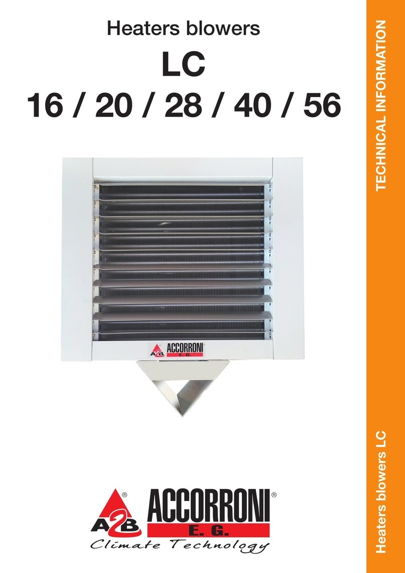
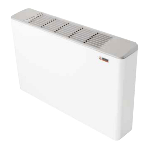
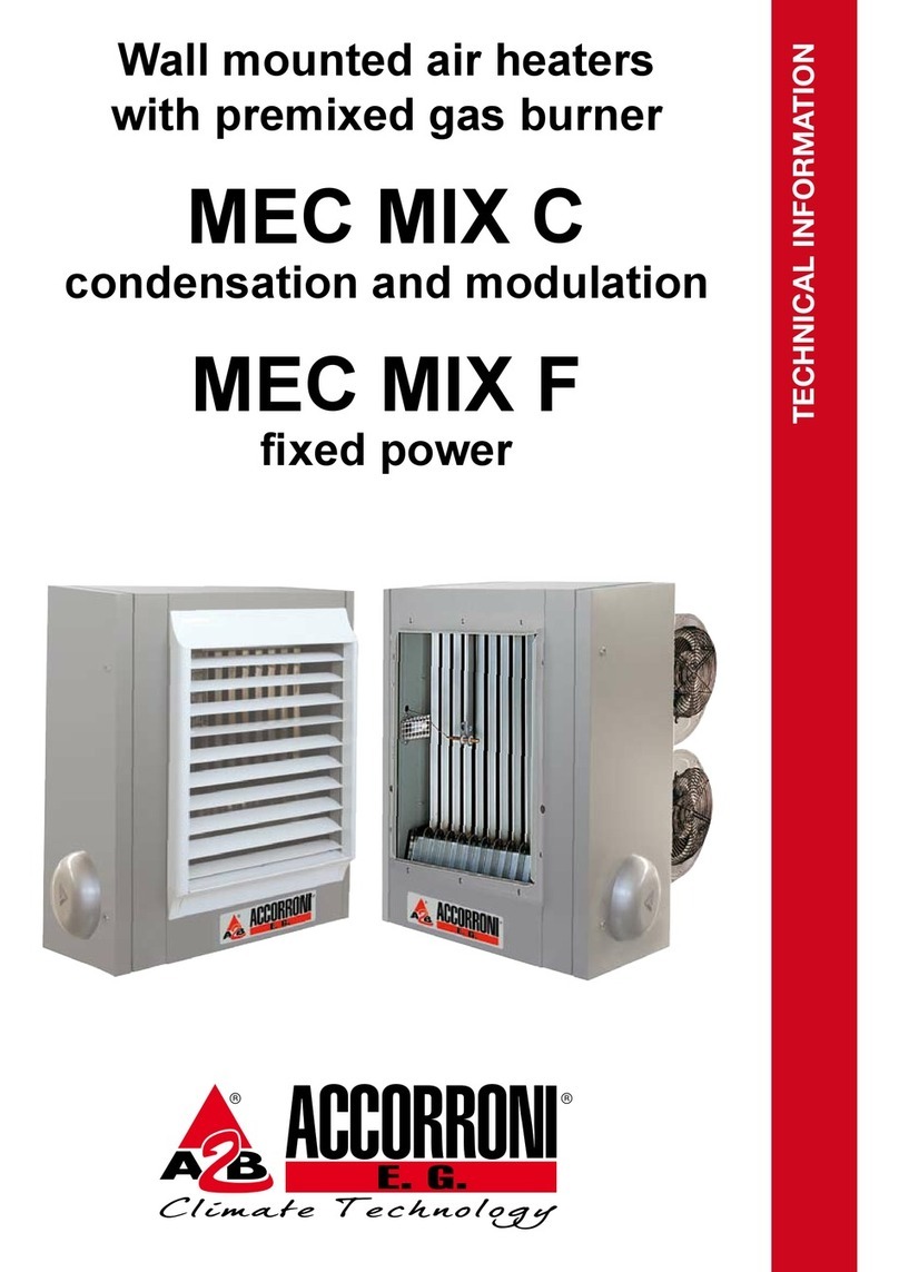
Accorroni MEC25-85 Manual

MEC 25÷85 - MEC 25÷85 C
MEC 25÷85
MEC 35÷85 C
Gas-fired air heaters
Technical information


GAS-FIRED AIR HEATERS
MEC - MEC C SERIES
Models 25 - 30 - 35 - 50 - 57 - 85
Technical information
This manual is divided into three sections:
-SECTION1-GENERALINFORMATION
Itcontainsalltheinformationrelativetothedescription of theairheatersandtheirtechnical features
-SECTION 2 - TECHNICAL INFORMATION FOR THE INSTALLER
Itcontainsalltheinstructionsandprescriptionsthatthetechnicalinstallermustcomplywithtoensure
effectiveplantoperation
-SECTION3 - USER OPERATING ANDMAINTENANCEINSTRUCTIONS
The section is reserved for the user and contains all the information needed to use the appliance
correctlyand toperform periodictests
Important notes:
1- Tousetheappliancecorrectlyandsafely,theinstaller,theuserandthemaintenanceman,fortheir
respectivecompetencies,mustcomplywithwhatisindicatedin this manual.
2- The word WARNING! is followed by information which, because of its importance, must be carefully
observedand forwhichnon-compliancemaydamage theapplianceand/orreduceoperatingsafety.
3- The paragraphs written with bold characters contain important information, warnings or
recommendationswhichshouldbecarefullyconsidered.
4- Thetechnicaldata,stylingcharacteristics,componentsandaccessoriesreportedinthismanualare
not binding. A2B Accorroni E.G. S.r.l. reserves the right to make changes, at any time, that are
considered necessary to improve the product.
5- Thelawful references,standardsortechnicalrulesmentionedinthismanualarepresentedmerely
for the sake of information and should be considered valid as of the date this manual is printed, as
indicatedonthe last page.Ifnew regulations oramendmentsto current lawsgointo effect, thiswill
not obligate A2B Accorroni E.G. S.r.l. in any way with regard to others.
6- A2BAccorroniE.G.S.r.l.isresponsibleforensuringthatitsproductconformstothelaws,directives
andconstructionstandardsinforceatthetimetheproductissold.Knowledgeandcompliancewith
legalregulationsandstandardsregardingplantdesign,installation,operationandmaintenanceare
the exclusive responsibility, for the respective competencies, of the designer, installer and user.
SUMMARY
SECTION1-GENERALINFORMATION page
1. PRINCIPALCHARACTERISTICS........................................................................................... 4
1.1 Applianceclassification ........................................................................................................... 4
1.2 Certification - ECmarking........................................................................................................ 4
1.3 Functionaldescription ............................................................................................................. 4
1.4 Constructioncharacteristics .................................................................................................... 5
1.5 Packagecontents.................................................................................................................... 5
1.6 Accessoriessuppliedonrequest ............................................................................................. 5
1.7 Fields of use............................................................................................................................ 6
1.8 Dimensions.......................................................................MECseries ................................... 7
1.9 Dimensions.......................................................................MEC C series .............................. 10
1.10 Explodedview ....................................................................................................................... 13
1.11 Wiringdiagram ...................................................................................................................... 17
1.12 Technical data table .............................................................................................................. 18

page2
2. CONTROLANDSAFETYDEVICES..................................................................................... 19
2.1 Controldevice ....................................................................................................................... 19
2.2 Gas unit................................................................................................................................. 19
2.3 Differentialpressureswitch ................................................................................................... 19
2.4 Fanthermostat ...................................................................................................................... 20
2.5 Safetythermostat .................................................................................................................. 20
SECTION 2 - TECHNICAL INFORMATION FOR THE INSTALLER
3. PRECAUTIONS .................................................................................................................... 21
3.1 GasSafetyRegulations......................................................................................................... 21
3.2 Relateddocuments................................................................................................................ 21
3.3 Transport and handling ......................................................................................................... 21
3.4 Datacheck ............................................................................................................................ 21
3.5 Using theinstructions ............................................................................................................ 21
4. INSTALLATION..................................................................................................................... 21
4.1 Location ................................................................................................................................ 21
4.2 Minimumheightsanddistances............................................................................................. 22
4.3 Air intakeand flue exhaustducts ........................................................................................... 23
4.4 Installationoperations............................................................................................................ 25
5. START-UP ............................................................................................................................ 26
5.1 Tests ..................................................................................................................................... 26
5.2 Ignition................................................................................................................................... 27
5.3 Usefulinformation.................................................................................................................. 28
6. GASTYPECHANGE ............................................................................................................ 28
6.1 Switching from gas in the second group to gas in the third group .......................................... 28
6.2 Switching from gas in the third group to gas in the second group .......................................... 29
7. OPERATINGDEFECTS........................................................................................................ 30
7.1 Preliminarytests .................................................................................................................... 30
7.2 Possibledefects .................................................................................................................... 30
8. REPLACINGPARTS............................................................................................................. 33
8.1 Controlequipment ................................................................................................................. 33
8.2 Fuse ...................................................................................................................................... 33
8.3 Gas solenoid valves .............................................................................................................. 33
8.4 Differentialpressureswitch ................................................................................................... 33
8.5 Control thermostat oftheconvection fan(s) ........................................................................... 34
8.6 Safetylimitthermostat ........................................................................................................... 34
8.7 Electrodes ............................................................................................................................. 35
8.8 Secondburnerignitiontransformer...................................- Model 85 ................................... 35
8.9 Flueexhaustfan.................................................................................................................... 36
8.10 Convectionfan ...................................................................................................................... 36
9. PERIODICMAINTENANCEOPERATIONS.......................................................................... 37
9.1 Userinformation .................................................................................................................... 37
9.2 Yearlyinspection ................................................................................................................... 37
10. HEALTHAND SAFETYSTATEMENT .................................................................................. 38
10.1 General ................................................................................................................................. 38
10.2 Cautionarynote ..................................................................................................................... 38
10.3 Miscellaneous ....................................................................................................................... 38
10.4 Thermostat ............................................................................................................................ 38
10.5 Electrolyticcapacitor ............................................................................................................. 38
SECTION3 - USER OPERATING ANDMAINTENANCEINSTRUCTIONS
11. START-UP ............................................................................................................................ 39
11.1 First firing and testing ............................................................................................................ 39
11.2 Tests ..................................................................................................................................... 39
11.3 Ignition................................................................................................................................... 39

page3
11.4 Shutdown .............................................................................................................................. 39
11.5 Summerventilation ................................................................................................................ 40
12. PLANTMAINTENANCE........................................................................................................ 40
12.1 Routinemaintenance to be performed by the user ................................................................ 40
12.2 Annualairheaterinspection .................................................................................................. 40
FIGURESUMMARY
Fig. no. ....................................................................................................................................... page
1 Dimensions.......................................................................- MEC 25 - 30 - 35......................... 7
2 Dimensions.......................................................................- MEC 50 - 57................................ 8
3 Dimensions.......................................................................- MEC 85....................................... 9
4 Dimensions.......................................................................- MEC C 25 - 30 - 35 ................... 10
5 Dimensions.......................................................................- MEC C 50 - 57 .......................... 11
6 Dimensions.......................................................................- MEC C 85 ................................. 12
7 Explodedview ..................................................................- Models 25 - 30 - 35 ................... 13
8 Explodedview ..................................................................- Models 50 - 57 .......................... 14
9 Explodedview ..................................................................- Model 85 ................................... 15
10 Wiringdiagram ...................................................................................................................... 17
11 Controldevice ....................................................................................................................... 19
12 Gasunit............................................................................- Models 25 - 30 - 35 ................... 19
13 Gasunit............................................................................- Models 50 - 57 - 85 ................... 19
14 Differentialpressureswitch ................................................................................................... 19
15 Fanthermostat ...................................................................................................................... 20
16 Safetythermostat .................................................................................................................. 20
17 Positionindications................................................................................................................ 22
18 Minimumdistances ................................................................................................................ 23
19 Type C12 installation............................................................................................................... 24
20 Type C52 installation............................................................................................................... 24
21 Type B22 installation............................................................................................................... 24
22 Connection of different units to one timer .............................................................................. 26
23 Remote-controlpanel ............................................................................................................ 27
24 Gasinjectorreplacement..................................................- Models 25 - 30 - 35 ................... 28
25 Gasinjectorreplacement..................................................- Models 50 - 57 .......................... 29
26 Gasinjectorreplacement..................................................- Model 85 ................................... 29
27 Gasinjectorinstallation ......................................................................................................... 30
28 Controlequipmentreplacement ............................................................................................. 33
29 Gasunitcoilreplacement .................................................- Models 25 - 30 - 35 ................... 33
30 Gasunitcoilreplacement .................................................- Models 50 - 57 - 85 ................... 33
31 Pressureswitchreplacement................................................................................................. 34
32 Fanthermostatreplacement .................................................................................................. 34
33 Safetythermostatreplacement .............................................................................................. 34
34 Electrodepositioning ........................................................- Models 25 - 30 - 35 ................... 34
35 Electrodepositioning ........................................................- Models 50 - 57 .......................... 35
36 Electrodepositioning ........................................................- Model 85 ................................... 35
37 Ignitiontransformerreplacement-2ndburner ..................- Model 85 ................................... 35
38 Flueexhaustreplacement.................................................- Models 25 - 30 - 35 - 50 - 57..... 35
39 Flueexhaustreplacement.................................................- Model 85 ................................... 36
40 Fanreplacement...............................................................- MEC.......................................... 36
41 Fanreplacement...............................................................- MEC C ...................................... 36
42 Cleaningtheexchanger......................................................................................................... 37
43 Remote-controlpanel ............................................................................................................ 39

page4
SECTION 1 - GENERAL INFORMATION
certificate” in conformity with EEC Directive 90/
396 and with reference to the harmonised
EuropeanstandardprEN1020.AttachingtheCE
marking shown below also guarantees that the
appliance conforms with EEC directive 73/23
(“Low voltage”) and EEC directive 89/336
(“Electromagneticcompatibility”).
1.3FUNCTIONALDESCRIPTION
TheMECwarmairheaterconsistsbasicallyofa
heatexchangeroperatingbetweenthecombustion
productsofagasburnerandtheairflowexerted
byone(models25-30-35),two(models50-57)or
threefans(model 85).
The air is drawn from the room by the fan(s),
conveyed to the exchanger which, operating to
the rated temperature by the burner, transfers
heat to the air.
WiththeMEC series appliances, thewarm air is
inserteddirectlyintotheenvironmentandtheflow
canbedirected using thelouvers,while with the
MEC C series appliances, the warm air can be
distributed in the rooms by using special ducts
anddeliveryoutlets.
Fan operation is controlled by a thermostat: to
prevent cold air from entering the environment,
thefanbeginsoperatingaftertheburnerisignited.
Instead,thefanisstoppedwithashortdelaywith
respect to when the burner is extinguished, to
allow the exchanger to cool off gradually.
Incaseofmalfunctionorifthefan(s)does(do)not
turn on and the exchanger overheats, a safety
thermostat trips and cuts off the gas flow to the
burner.
Thecombustionproductsareexhaustedoutdoors
byacentrifugalfaninstalledafterthecombustion
circuit.Iftheductsareobstructedorthefandoes
notwork,adifferentialpressureswitchcutsoffthe
gas flow to the burner.
Airheateroperationcanbecontrolledbyaroom
thermostat(notsupplied)orfromaremote-control
panel (supplied on request). With the remote-
1. PRINCIPAL CHARACTERISTICS
1.1APPLIANCECLASSIFICATION
These appliance are defined as “Gas-fired air
heaters with an atmospheric burner equipped
with a fan in the combustion circuit”.
In addition, they are classified according to
harmonised European standards EN 437 and
prEN 1020 into:
category - according to the types of gas, at the
different supply pressures, that they can use;
type-accordingtothepossiblemethodstoexhaust
thecombustionproductions(seealso4.3.1).
1) Category II2H3+
the air heater is suitable to use gas that belongs
to two families. The atmospheric burner can be
fed with the gas from the second group (natural
gas - group H) and the gas from the third group
(butaneandpropaneatthetwopressureratings
28-30and 37mbar)
2) Type C12
The combustion circuit is sealed with respect to
the environment in which it is installed and the
combustion air supply and combustion product
exhaustlinesareconnectedoutsidetheroomby
means of ducts which pass directly through the
outsidewalloftheroom,includingterminalswithin
a square with a 50 cm side.
3) Type C52
Thecombustioncircuitishermeticallysealedwith
respecttotheenvironmentinwhichitisinstalled
and the combustion air supply and combustion
productexhaustlinesareconnectedoutsidethe
room by means of ducts with terminals located
also on walls not in the room. The combustion
products can be exhausted also with a special
duct on the roof of the building.
4) Type B22
Combustion air intake is performed within the
environment,whilethecombustionproductsare
exhausted through a duct that passes directly
through an external wall or on the roof of a
building.
1.2 CERTIFICATION - EC MARKING
The MEC air heaters, as previously described
and classified, have obtained the “CE type test

page5
control panel the air heater can be used, during
thesummer,justtoventilatetheroom,excluding
theburneroperation.
1.4CONSTRUCTIONCHARACTERISTICS
The casing is built with epoxy-powder painted
steelplate to guarantee extended service life.
Theair delivery openingis located inthe front of
the appliance along with the horizontal louvers
whichcanbeadjustedmanually(MEC),orwitha
specialconfigurationtoconnectducts(MECC).
The exchanger is equipped with the ventilation
thermostatand thesafetythermostatbulb.
Therearofthe appliance includes the following:
- the axial (MEC) or centrifugal (MEC C)
convection fan(s) with safety grille
- the connectors to attach the combustion air
inletandcombustionproductexhaustducts
- the gas supply connector
- the electric cable entries
Thefollowingisinstalledinaservicedooronthe
rightside:
- the electric board with relative wiring
- the burner control device
- the appliance reset button with relative
illuminatedsignal
- thesafetythermostat
- thedifferentialpressureswitch
- the gas unit
- theflueexhaustfan (except model 85)
Instead,onlyforthemodel85,theservicedooron
the left side contains the following:
- theignitiontransformer,withrelativeelectrode,
serving the second burner
- thegasconnectorandheaderwithinjectorsto
feed the second burner
The interior of the appliance includes:
- the combustion chamber and the stainless
steelheatexchangers
- the flue exhaust fan (model 85 only)
- thestainlesssteelatmosphericburnerincluding
ignitionelectrodesandflamedetector(inmodel
85 there are two burners installed in opposite
positions)
1.5PACKAGECONTENTS
Theairheaterisshippedwithcardboardpacking
and internal protective pieces in pre-formed
cardboard.Thereisanenvelopeinsidetheservice
door of the appliance containing: this technical
information manual, the warranty and service
documents,whatisneededtochangethetypeof
gas, along with the relative adhesive label and
plug for the combustion product intake hole.
1.6ACCESSORIESSUPPLIEDONREQUEST
In addition to the material described above, the
following accessories can also be supplied on
request:
- remote-control panel, including the principal
operatingcommandsandsignals
- support brackets designed to attach the
appliance in a hanging position, for air heater
versionswithaxial(MEC)andcentrifugal(MEC
C) fans
- combustion product exhaust kit for horizontal
wall-mounted exhaust layouts including: rigid
duct,length1metre,jointsandwindprotection
terminal(ductdiameter80mmuptomodelMEC
/MECC35,100mmformodelsMEC/MECC
from 50 to 85)
- rigid pipes, 45° and 90° bends, 90° bend with
condensate drain, connectors and wind
protectionterminalstocreatedifferentexhaust
configurations,includingtheverticalrooflayout
- kittosupplycombustionairfromoutdoorswith
protectionterminal
- additional air delivery grille with adjustable
verticallouvers (MEC)
- drilled polyethylene pipe Ø 400 mm for air
distribution in agricultural and zoo-technical
applications
- circular connectors for air delivery in
polyethyleneduct
- air intake connector duct (MEC C)

page6
1.7 FIELDS OF USE
MECandMECCairheaterscanbeusedtobuild
modular plants, consisting of one or more
appliances,tomeettheheatingrequirementsof
smallspacessuchasartisanlaboratories,etc.,up
to large volumes, such as industrial sheds,
warehouses,churchesand sports facilities.
Therefore, the heat dispersion of the building
mustbecalculatedaswellastherequiredheating
power, selecting the number and type of air
heatersinrelationtothevalues,suchas:airflow
andthrow,headavailablewhenusingdistribution
ducts, effective coverage of the areas to be
heated, any air changes, etc.
The MEC and MEC C air heaters are built for
installation in rooms, whether they are specially
designed for the appliances (technical room) or
otheractivities(i.e.directlyinsidetheenvironment
tobeheated).Thequalityandthedimensionsof
thematerialsusedhavebeenchosentoguarantee
a reasonable service life and are suitable to
operatetheappliances,bothintheirentiretyand
relativetotheirparts,providedthattheappliances
areprofessionallyinstalledandaresubjectedto
mechanical, chemical and thermal stress
conditionscorrespondingtonormaluse.
The air heater must not be installed under
conditionsforwhichitwasnotspecificallydesigned,
e.g.wheretheatmosphereishighlycorrosiveor
salty.
For “open” outdoor installations, it is
necessary to use the MEC EX series air
heaters, which go beyond the scope of this
manual and which have been specifically
designed and built for this purpose.
Based on what is prescribed by the current
installation standards, the MEC and MEC C air
heaterapplicationsmaybesummarisedasfollows:
- MECseriesairheaterswithaxial,free-delivery
fans can be used if there are no special air
distribution problems or there are no physical
obstaclestoobstructsuchdistribution,suchas
partitions, shelving or bulky machinery, etc. In
thesecases,theeffectivecoverageoftheareas
tobeheatedmustbeevaluatedinrelationtothe
air throw of the appliances
- MEC C air heaters with ductable centrifugal
fanscanbeusedforthecasesinwhich,unlike
whatwasdescribedinthepreviousparagraph,
it is not possible to serve the desired area
efficientlywiththefreeairdelivery.TheMECC
air heaters are also suitable if a filter must be
appliedtotheairintake(infact,centrifugalfans
are needed due to the load losses induced by
that filter) and/or a change is required with
outdoor air, to be conveyed by ducts.
WARNING! It is important to verify that the
designandinstallationconformwithcurrent
standards. Ensure that the environment in
which the air heater will be installed will not
create a hazard, i.e. where excessive (vola-
tile)dust,flammableorcorrosivesubstances
and/or vapours and combustible materials
may be present.

page7
ABCDEFGH I LM
695 415 840 477 470 400 120 695 93 528 113
N O P Q R S T U Air
Flue gas
Gas
283 440 35 62 48 315 76 398 Ø140 Ø 80 R 1/2"
1.8 DIMENSIONS - MEC series with axial fans - Models 25 - 30 - 35
Fig. 1
Air inlet
Exhaustoutlet
Gasinlet
ISO 7/1 R 1/2

page8
ABCDEFGH I LM
1.147 415 840 477 922 400 113 684 93 528 113
N O P Q R S T U Air
Flue gas
Gas
290 440 35 62 48 315 81 840 Ø140 Ø 100 R 1/2"
Fig. 2
1.8 DIMENSIONS - MEC series with axial fans - Models 50 - 57
Exhaustoutlet
Air inlet
Gasinlet
ISO 7/1 R 1/2

page9
ABCDEFGH I LM
1.748 480 870 542 1.358 400 1.133 715 874 133 113
N O P Q R S T U Air
Flue gas
Gas
353 515 35 62 48 315 424 900 Ø140 Ø 100 R 1/2"
Fig. 3
1.8 DIMENSIONS - MEC series with axial fans - Model 85
Exhaustoutlet
Air inlet
Gasinlet
ISO 7/1 R 1/2

page10
ABCDEFGH I LM
695 415 840 797 470 400 120 695 93 528 113
N O P Q R S T U Air
Flue gas
Gas
283 440 35 382 48 315 76 398 Ø140 Ø 80 R 1/2"
1.9 DIMENSIONS - MEC C series with centrifugal fans - Models 25 - 30 - 35
Fig. 4
Exhaustoutlet
Air inlet
Gasinlet
ISO 7/1 R 1/2

page11
ABCDEFGH I LM
1.147 415 840 797 922 400 113 684 93 528 113
N O P Q R S T U Air
Flue gas
Gas
290 440 35 382 48 315 81 840 Ø140 Ø 100 R 1/2"
Fig. 5
1.9 DIMENSIONS - MEC C series with centrifugal fans - Models 50 - 57
Gasinlet
ISO 7/1 R 1/2
Air inlet
Exhaustoutlet

page12
ABCDEFGH I LM
1.748 480 870 862 1.358 400 1.133 715 874 133 113
N O P Q R S T U Air
Flue gas
Gas
353 515 35 382 48 315 424 900 Ø140 Ø 100 R 1/2"
Fig. 6
1.9 DIMENSIONS - MEC C series with centrifugal fans - Model 85
Exhaustoutlet
Air inlet
Gasinlet
ISO7/1R1/2

page13
Fig. 7
1.10 EXPLODED VIEW - Models 25 - 30 - 35

page14
1.10 EXPLODED VIEW - Models 50 - 57
Fig. 8

page15
1.10 EXPLODED VIEW - Model 85
Fig. 9

page16
Parts legend
1 Atmosphericburner
2 Burnerinsulating gasket
3 Gasinjectors
4 Ignitionelectrode
5 Flamedetectionelectrode
6 Secondignitiontransformer (model 85)
7 Completegas unit
8 “T” gas fitting (model 85)
9 Gas supply pipe for 2nd burner (model 85)
10Control device
11 Printed circuit board
12Radio interference filter
13 Cable gland
14 Reset button
15Differential pressure switch
16 Silicon pressure switch tube
17Safetylimit thermostat
18Limitthermostat support
19Fan control thermostat
20Fan control thermostat protection
21Flue exhaust fan
22Flueexhaust diaphragm (models 25-30-35-50-57)
23 Flue exhaust stainless steel duct
24Axialfan (MEC)
25Axialfanprotection grille
26Fan condenser
27Flue exhaust condenser
28 Centrifugal fan (MEC C)
29 Centrifugal fan protection grille
30Remote-control panel (suppliedon request)
31Combustionchamber/exchanger
32Fluegas mixers
33 Flue gas deflector
34Exchangercover
35Combustion air deflector (models50-57-85)
36 Burner air header (model 85)
37 Front panel with delivery grille (MEC)
38 Rear panel with delivery outlet (MEC C)
39 Top panel
40Bottom panel
41Side panel (models 25-30-35-50-57)
42 Rear panel (MEC)
43 Rear panel (MEC C)
44Side box
45 Service door
46 Lock

page 17
Fig. 10
Ac = Control equipment
Br1 = Burner
Br2 = Secondburner(MEC85)
C1 = Fanmotorcondenser
C2 = Flueexhaustmotorcondenser(MEC 85)
Cs = Printedcircuit board
Ea1 = Ignitionelectrode
Ea2 = Br2 ignition electrode (MEC 85)
Ef1 = Flueexhaustmotor(MEC25-57)
Ef2 = Flue exhaust motor (MEC 85)
Er = Flamedetectionelectrode
Ev = Gassolenoidvalve
Fr = Radiointerferencefilter
M1 = Ef2connection terminal boards(MEC 85)
Mvc1 = Centrifugalfanmotor(MECC25-85)
Mvc2 = Centrifugalfanmotor(MECC50-85)
Mvc3 = Centrifugalfanmotor(MECC85)
Mve1 = Axialfanmotor(MEC 25-85)
Mve2 = Axialfanmotor(MEC 50-85)
Mve3 = Axial fan motor (MEC 85)
Op = Jumperforauxiliaries
P= Differentialpressureswitch
R1 = Fanrelay (MEC C)
R2-R3 = Fan relay (MEC C / MEC 85)
Rs = Resetbutton
Sb = Lockoutsignal
Tr = Br2ignitiontransformer(MEC85)
Ts1 = Safetythermostat
Ts2 = Second safety thermostat (MEC 85)
Tv = Fanthermostat
= Fuse
- - - - - = Connectionto bemade
= Seriesconnection
= Varyingconnection(modeldepending)
Warning:
- Install an omnipolar switch with a contact opening of at
least 3 mm.
- The 230 V ~ 50 Hz single-phase power supply must be
connectedaccordingtothephase-neutral polarity.
Cable colors [b] = blue
[bi] = white
[g] = yellow
[g/v] = yellow/green
[gr] = grey
[m] = brown
[n] = black
J15
J14
J13
J12
J11
J10
J9
J8
J7
J6
J5
J4
J3
J2
J1
J25
J26
J27
J28
J29
J30
J31
J32
J33
J34
J35
J36
N
L
J23
J24
Ef2
C2
M1
[b]
[n]
[m]
1
2
3
1a N
J1 J2 J3 J4
N 1a N 1a
PEf1
NONC
C
Ts1
Ts2
Tr
Br2
Ea2
Br1
Ea1 Er
Ev
Ac
K3 K1 K2
Tv
L
N
SB
RS
J22
J21
J20
J19
J18
C1
R1 R2
J17
J16
R3
[b]common
[m]condenser
[n2]max.
[n1]min.
Mvc1
3(U)
1(U)
(4)
(2)
Fr
N
L
230 V ~
50 Hz
[b]common
[m]condenser
[n2]max.
[n1]min.
Mvc2
[b]common
[m]condenser
[n2]max.
[n1]min.
Mvc3
Op Sb Rs
Cs
3
1
2
[m]condenser
Mve1
[b]common
[m]condenser
[g]max.
Mve2
[b]common
[m]condenser
[g]max.
Mve3
L N SB RS
L N 1a N
ELECTRICAL SCHEMA FOR AXIAL FAN
page 24
Fig. 19
Fig. 20
Topview Sideview
Topview
Terminals far apart and
locatedondifferentwalls
Type C52
The combustion circuit is
hermetically sealed with
respecttotheenvironment.
Both types of ducts are
connectedtotheoutdoors,
buttheirterminalsmayalso
be located on walls not in
theroom.
Type C12
The combustion circuit is
hermetically sealed with
respecttotheenvironment.
The ducts pass directly
throughtheoutsidewallof
the room, with terminals
close to each other.
Fig. 21
Sideview
Exhaust directly through
theexternalwall
Sideview
Verticalexhaustabove
the roof of the building
Type B22
Open combustion circuit
with combustion air taken
fromwithintheenvironment.
In this case the correct
amount of combustion air
must be guaranteed by
meansofsuitableopening
inthewalls.
Minimum
20 cm
8 cm
Sideview
Wall exhaust and discharge
above the roof of the building
L
[g/v]
N
[b][m][n]
J27 J26 J25
[n
]common
[b]max.
1.11 WIRING DIAG
R
AM
M
E
C
35
-
35
C-57-5
7C-85-85
C
J25
J26
J27
J28
J29
J30
J31
J32
J33
J34
J35
J36

page 17
Fig. 10
Ac = Control equipment
Br1 = Burner
Br2 = Secondburner(MEC85)
C1 = Fanmotorcondenser
C2 = Flueexhaustmotorcondenser(MEC 85)
Cs = Printedcircuit board
Ea1 = Ignitionelectrode
Ea2 = Br2 ignition electrode (MEC 85)
Ef1 = Flueexhaustmotor(MEC25-57)
Ef2 = Flue exhaust motor (MEC 85)
Er = Flamedetectionelectrode
Ev = Gassolenoidvalve
Fr = Radiointerferencefilter
M1 = Ef2connection terminal boards(MEC 85)
Mvc1 = Centrifugalfanmotor(MECC25-85)
Mvc2 = Centrifugalfanmotor(MECC50-85)
Mvc3 = Centrifugalfanmotor(MECC85)
Mve1 = Axialfanmotor(MEC 25-85)
Mve2 = Axialfanmotor(MEC 50-85)
Mve3 = Axial fan motor (MEC 85)
Op = Jumperforauxiliaries
P= Differentialpressureswitch
R1 = Fanrelay (MEC C)
R2-R3 = Fan relay (MEC C / MEC 85)
Rs = Resetbutton
Sb = Lockoutsignal
Tr = Br2ignitiontransformer(MEC85)
Ts1 = Safetythermostat
Ts2 = Second safety thermostat (MEC 85)
Tv = Fanthermostat
= Fuse
- - - - - = Connectionto bemade
= Seriesconnection
= Varyingconnection(modeldepending)
Warning:
- Install an omnipolar switch with a contact opening of at
least 3 mm.
- The 230 V ~ 50 Hz single-phase power supply must be
connectedaccordingtothephase-neutral polarity.
page 24
Topview
Topview
Terminals far apart and
locatedondifferentwalls
Type C52
theroom.
Type C12
The combustion circuit is
hermetically sealed with
respecttotheenvironment.
The ducts pass directly
throughtheoutsidewallof
the room, with terminals
close to each other.
Sideview
Exhaust directly through
theexternalwall
Type B22
inthewalls.
1.11 WIRING DIAG
R
AM
M
E
C 25
J15
J14
J13
J12
J11
J10
J 9
J 8
J 7
J 6
J 5
J 4
J 3
J 2
J 1
J25
J26
J27
J28
J29
J30
J31
J32
J33
J34
J35
J36
N
L
J23
J24
Ef2
C2
M1
[b]
[n]
[m]
1
2
3
LN1aN1a N
J1 J2
LNSBRS
J3 J4
N1aN1a
PEf1
NONC
C
Ts1
Ts2
Tr
Br2
Ea2
Br1
Ea1 Er
Ev
Ac
K3K1K2
Tv
L
N
SB
RS
J22
J21
J20
J19
J18
C1
R1R2
J17
J16
R3
3(U)
1(U)
(4)
(2)
Fr N
L
230V~
50 Hz
Op Sb Rs
Cs
3
12
Mve1
L
[g/v]
N
[b]
[n]
[b]
max.
[m][n]
J27 J26 J25
L M M 1 2 3 4 5 6
ATr
Cable colors [b] = blue
[bi] = white
[g] = yellow
[g/v] = yellow/green
[gr] = grey
[m] = brown
[n] = black
ATr =A
u
t
o
t
ra
nsf
o
rme
r
ELECTRICAL SCHEMA FOR AXIAL FAN
common
condenser
[m]
This manual suits for next models
1
Table of contents
Other Accorroni Heater manuals
Popular Heater manuals by other brands

Rinnai
Rinnai RHFE-556FTR user guide

Raider
Raider Power Tools RD-EFH03 user manual

Hidrotermal
Hidrotermal Hidro-H5.5 user manual

Atlantic
Atlantic SOLIUS instruction manual

Kermi
Kermi PUR1E Series Instructions for installation and use

CIAT
CIAT Divio Series Installation, Operation, Commissioning, Maintenance