2APRIL 2009 Issue (Italy)
3APRIL 2009 Issue (Italy)
1D.H.W. HEATER CATEGORY
These devices are classified as generator of hot water with sealed
combustion chamber and atmospheric burner.
They are classified in the category II2H3+,it means that they can be
used with the gas of second class: natural, methane H and of third
class Lpg butane, propane.
As for the European norm EN 483 they are identified referring with
the system for air aspiration and fumes drain C13,C23,C53.
2PACKAGING
Fig. 01
Mod. N. pack Dimensions (h x l x p) (mm) Weight (Kg)
220 1 1650 x 780 x 780 160
300 1 2000 x 780 x 780 187
400 1 1800 x 820 x 820 200
500 1 2080 x 820 x 820 232
800 1 2150 x 1100 x1100 335
The water heater is supplied in a case of wood, with one envelope,
in the frontal containing the present manual and the certificate of
guarantee.
3DESCRIPTION OF THE WATER HEATER
The water heater is composed from a water tank lodged over to
a combustion chamber where the heat necessary is developed in
order to heat the water.
The produced smoke therefore yields their heat to the water in
their fireplace towards the outside, passing through the tubes, the
exchanger dipped in the water.
On the high part a canopy collects the fumes from the exchanger and
drives them to the drainage system. A fan is situated in the upper
cap it, supplies the feeding of the air and the evacuation of the
products of combustion. The tank is constructed in sturdy sheet iron
and guarantees a remarkable resistance to pressure it’s moreover
glass lined at 860°. This concurs to obtain an optimal unassailable
chemical resistance (from organic solvent and from chemical
substances), an optimal thermal stability; the enamel resists until
500° The inner inspection and cleaning from the incrustations is
possible through the flange 120 mm diameter.
The combustion chamber is placed in the low part of the water
heater and it contains the atmospheric burner and flame probes.
Combustion chamber is completely sealed from the place where it
is installed.
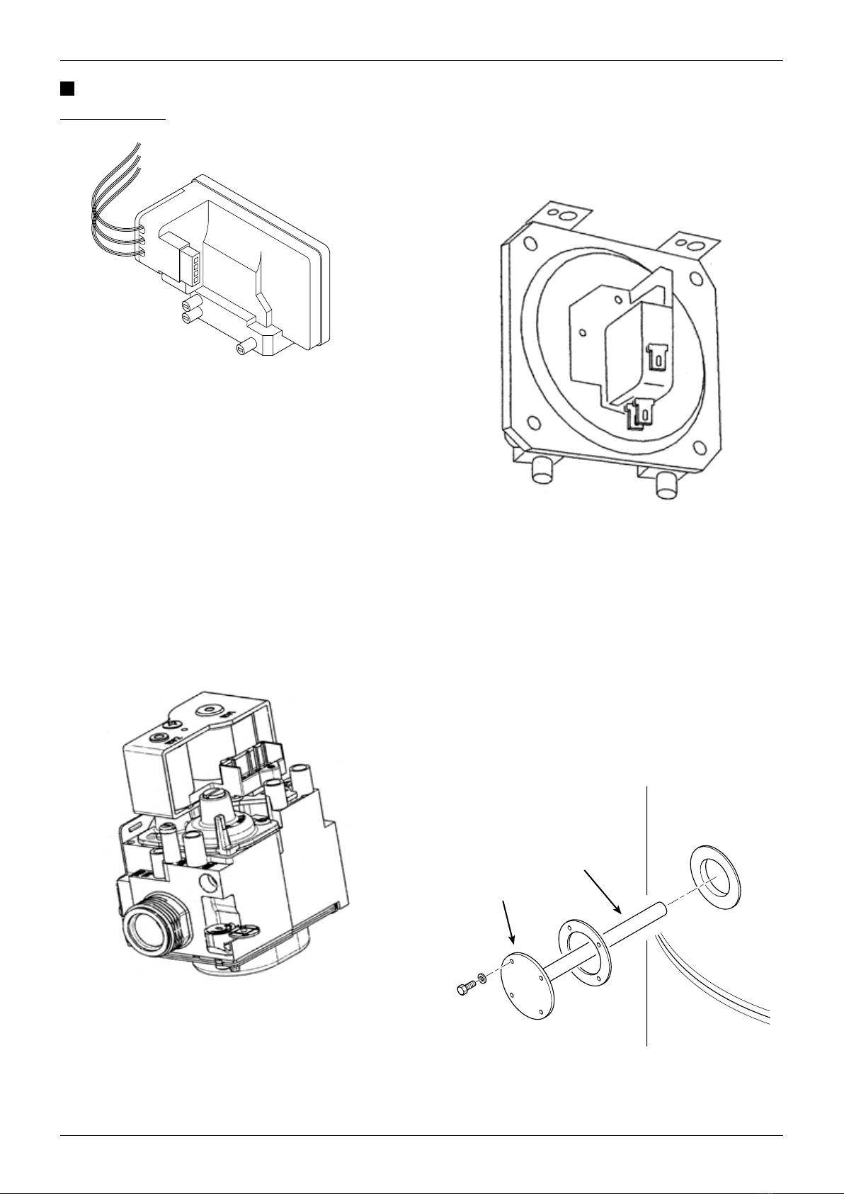
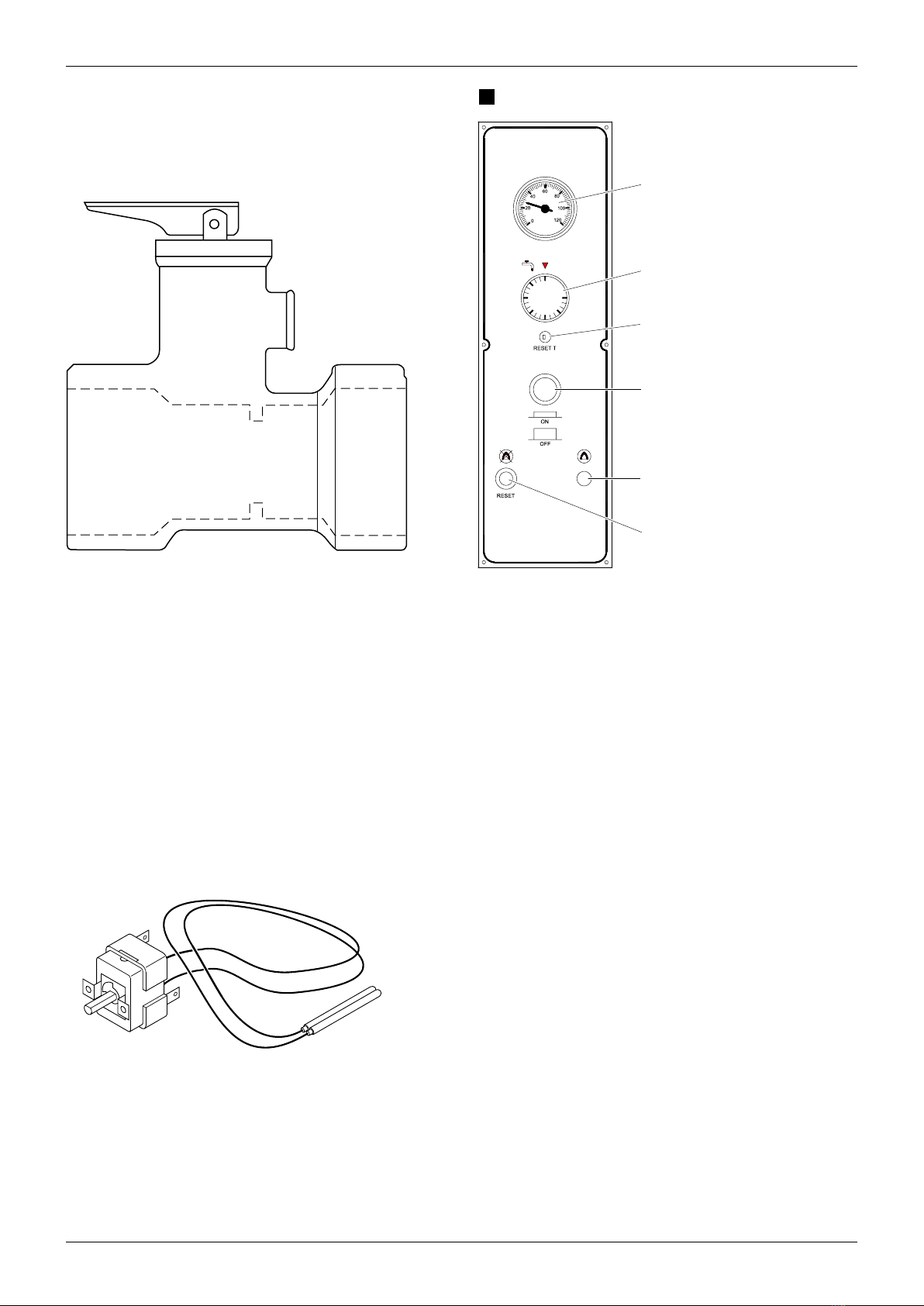
Control Panel
The control panels contains all the components in order to adjust
the normal operation of the water heaters: thermostat, ignition
device, luminous release button, thermometer etc..
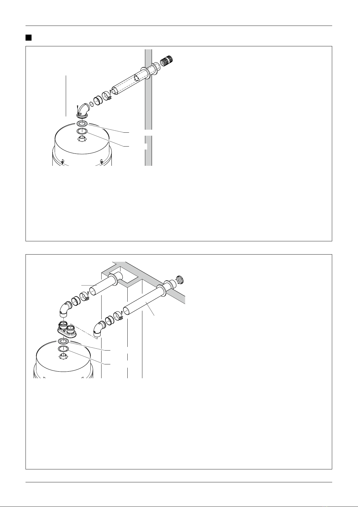
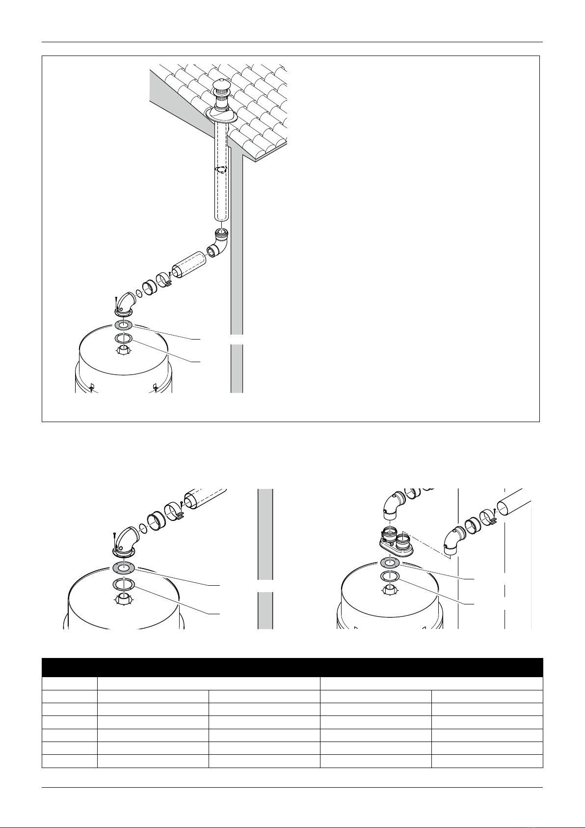
KIT OF SMOKE DRAINAGE (supplied separately)
As for the different requirements of Installation it can be:
• Concentric with drainage and aspiration to the wall
• Concentric with drainage and aspiration to the wall
• Divided with drainage and aspiration to the wall, to the roof or
in a fume pipe.
DESCRIPTION OF THE APPLIANCE 4TEST OF THE WATER HEATER AND SECURITY
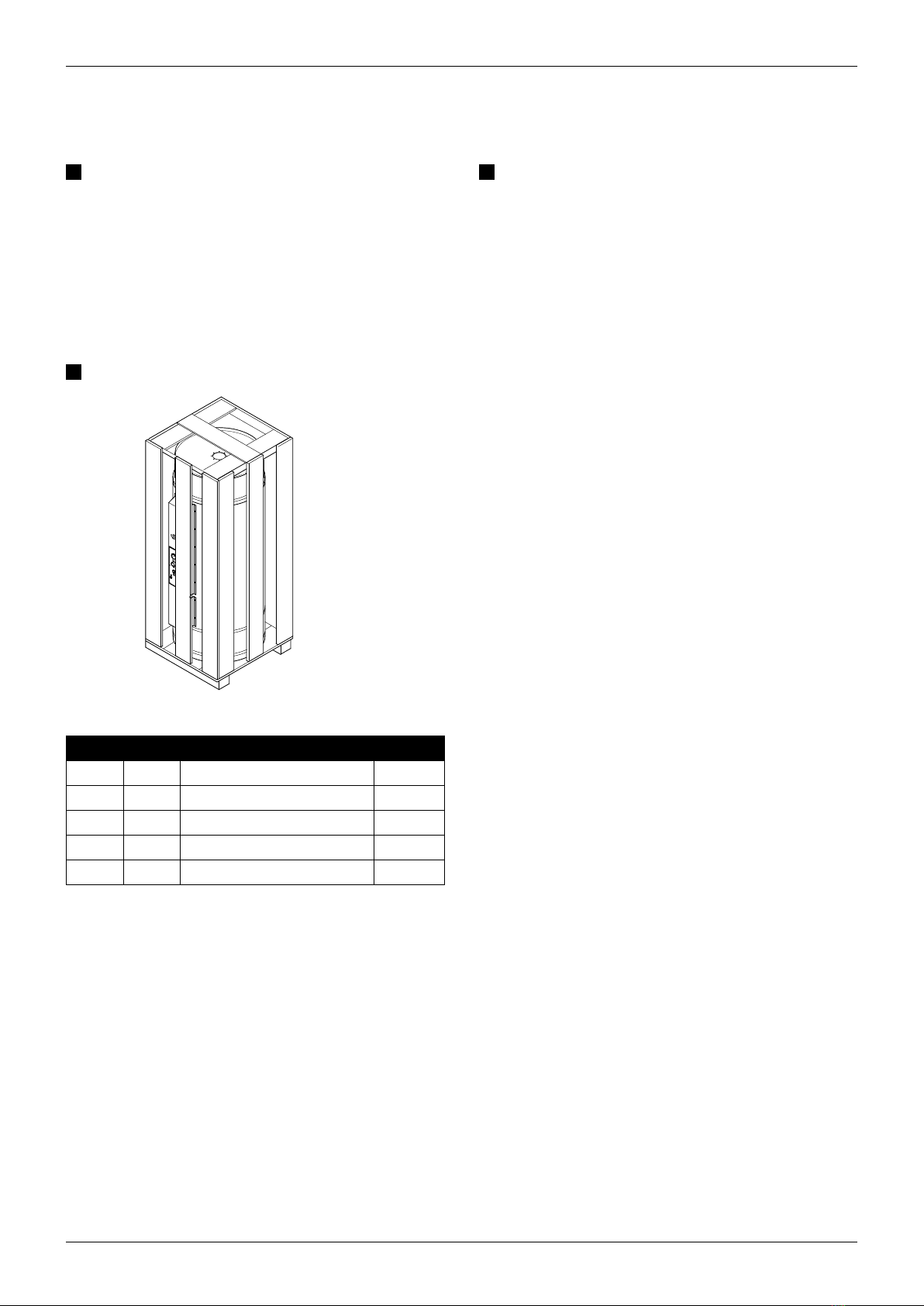
Electronic ignition card
Fig. 02
It controls the opening of the gas valve and the burner ignition. Since
when it receives the electrical feeding from the thermostat it initially
checks that the contacts of the pressostat are in position of operation
otherwise there is no ignition; on the contrary, subsequently, it makes
a pre ventilation cycle of the combustion chamber and the ignition
spark, if during this cycle it does not find the flame of ignition in the
pre fixed time, it is placed in block position; in it this case please wait
some second and then press the luminous reset key.
The survey of the flame happens for ionization through appropriate
probe on the burner, CE Homologated EN 298.
GAS VALVE
It is made of one multifunctional multigas valve with double safety B class
for silent operation.
The valve is equipped of pressure regulator and device for the slow ignition,
with adjustable gas capacity (factory pre setted) Homologated as for norms
EN 126.
Fig. 03
The body is in fused aluminium it is supplied of inlet and outlet gas
connection 1/2”. The unit is supplied of inlet gas filter.
The two electro valves are connected in series on the main pipe of
the gas and are feeded by co a single tripolar connector, to avoid
wrong connections. All the operations of calibration and regulation
must be executed from qualified staff.
In case of replacement of the valve be sure that the flow of the gas
is in compliance with the arrow on the body of the valve and that
during the assembly operations external substances do not enter.
AIR PRESSOSTAT
Fig. 04
The function of this device is to control the combustion, interrupting
the operation of the burner in case of insufficient capacity of the
fan.
The device has 3 contacts,( two positions, one normally in open
position NA, the other normally closed NC.
MAGNESIUM ANODE
Magnesium anode is important to protect the water heater from
corrosion and galvanic currents. It is suggested to replace the anode
once every year, the anode is placed in the inspection flange, in the
frontal part of the tank.
Fig. 05