Accorroni FR-FC-FCO-FCR Series Manual

Technical Information
FR - FC - FCO - FCR 100÷800
Fan coil units series
FR - FC - FCO - FCR
Models100÷800

FAN COIL UNITS
SERIES FR - FC - FCO - FCR
Models100-200-300-400-600-800
Technical details
This manual is in three sections:
-SECTION A - GENERAL INFORMATION
Contains descriptions and technical details of the equipment.
-SECTION B - INSTALLATION DETAILS FOR THE INSTALLER
Contains all the instructions and notes necessary for installing equipment.
-SECTION C - USER INSTRUCTION AND MAINTENANCE MANUAL
Thissectionisfortheuser'suseandcontainsallthenecessaryinformationforthecorrectusageand
periodic checks on the equipment.
Important notes for using the manual:
1- To ensure correct and safe use of the appliance, the planner, installer, user and maintenance
technician respectively must scrupulously observe everything contained in this manual. The
manualmustbe heldfor referenceandmust bekeptwiththeappliance forthelength ofits working
life, including in the case of its transfer to a third party.
2- The word WARNING! indicates information of great importance which must be strictly observed.
Non-compliancewiththisinstructioncouldresultindamagetotheapplianceand/ordangerinusing
it. Paragraphs written in bold contain important information, advice or instructions which must be
carefully considered.
3- AccorroniS.r.l.isnot responsible foranydamagecaused by theimproperuse of the appliance,by
anyusedifferentfromtheonedesignatedorbyanyincompleteorapproximateconformationtothe
instructions in this manual.
4- Thetechnicaldata, physicalappearance,componentsand accessoriesshownin thismanualmay
be subject to change. Accorroni S.r.l. reserves the right to make any changes at any time that it
considers necessary for improving the quality of the product.
5- References to laws, norms and technical regulations in the manual are for information purposes
onlyandarevalidatthedateofprintingshownonthelastpage. AccorroniS.r.l.hasnoresponsibility
to third parties arising out of implementation of new provisions or changes to existing ones.
6- Accorroni S.r.l. is responsible for ensuring that the product conforms to the production laws,
regulations and norms in force at the time of putting the product on the market. Knowledge and
observance of the laws and regulations appropriate to the plant design, installation, use and
maintenance of the appliance are the exclusive responsibility of the planner, installer and user
respectively.
INDEX
SECTION A - GENERAL INFORMATION page
1. PRINCIPAL CHARACTERISTICS......................................................................................... 3
1.1 Appliance classification........................................................................................................... 3
1.2 EC conformity ......................................................................................................................... 3
1.3 Functional description ............................................................................................................. 3
1.4 Technical characteristics........................................................................................................ 3
1.5 Pack contents ......................................................................................................................... 4
1.6 Optional accessories .............................................................................................................. 4

pag. 2
1.7 Measurements ........................................................................................................................ 6
1.8 Components ........................................................................................................................... 8
1.9 Technical data tables............................................................................................................ 13
1.10 Standard 3 row battery heat output diagrams ....................................................................... 14
1.11 Standard 3 row battery charge loss for water at 10°C diagrams .......................................... 17
1.12 Electrical Diagrams .............................................................................................................. 20
SECTION B - INSTALLATION INSTRUCTIONS
2. WARNINGS ......................................................................................................................... 22
2.1 Installerqualifications ............................................................................................................ 22
2.2 Preliminary information ......................................................................................................... 22
2.3 Transport and handling ......................................................................................................... 22
2.4 Data control .......................................................................................................................... 22
2.5 Instruction use....................................................................................................................... 22
3. INSTALLATION.................................................................................................................... 23
3.1 Positioning ............................................................................................................................ 23
3.2 Installationprocedures .......................................................................................................... 23
4. STARTING UP .....................................................................................................................25
4.1 Checks.................................................................................................................................. 25
4.2 Starting up............................................................................................................................. 25
5. REPLACING COMPONENTS............................................................................................. 26
5.1 Fan group.............................................................................................................................. 26
5.2 Heatexchanger..................................................................................................................... 26
SECTION C - USER INSTRUCTION AND MAINTENANCE MANUAL
6. WARNINGS ......................................................................................................................... 27
6.1 Instructions and guarantee.................................................................................................... 27
6.2 Recommendations - improper use ....................................................................................... 27
7. STARTING UP .....................................................................................................................28
7.1 Checks.................................................................................................................................. 28
7.2 Turning on ............................................................................................................................. 28
7.3 Turning off ............................................................................................................................. 28
8. MAINTENANCE................................................................................................................... 28
8.1 Normal user maintenance..................................................................................................... 28
8.2 Regular checks..................................................................................................................... 29
8.3 Trouble-shooting ................................................................................................................... 29
APPENDICES
EC conformity declaration..................................................................................................... 30

pag. 3
SECTION A - GENERAL INFORMATION
1.PRINCIPALCHARACTERISTICS
1.1 APPLIANCE CLASSIFICATION
The F-FR-FC-FCR fan heaters are defined as
"air treatment terminals for winter and summer
airconditioning".
1.2 EC CONFORMITY - CERTIFICATION
The EC symbol guarantees that the appliance
conforms to EEC machinery directive EEC/98/
37, low tension directive EEC/73/23,
electromagnetic directive EEC/89/336 and any
subsequent amendments. The appliances have
the Eurovent certificates and the symbol
guarantees conformity to the data declared.
1.3 FUNCTIONAL DESCRIPTION
The fan heaters consist essentially of a system
of heat exchange between the liquid circulating
inside the exchanger (hot or cold water) and the
air flow controlled by a fan system. The outside
airistakeninbythefansandsentouttotheheat
exchanger which heats the air in winter or cools
it in summer. During the summer cycle,
dependingontheheat-hygrometricconditionsof
the outside air, water condensation is formed
andcollectedintheappropriatecontainersothat
it can be disposed of.
The treated air is emitted through the appliance
grilleorthroughtheoutletunitsbuiltintotheplant.
The appliances come as standard with fittings
for2pipes. For4-pipeplantswithtwoindependent
circuits,thereisanoptionalsupplementaryheat
exchangesystem. Thefan heaterhasa remote
control (supplied separately). A choice can be
made from various available versions.
1.4 ASSEMBLY CHARACTERISTICS
1.4.1 Available versions
Thefanheatersareavailablein6differentsizes
and in the following versions:
FR- Vertical with casing
For wall installation, under windows or in
anyotherfreespaceorpositionwhichoffers
technical or functional advantages.
FC- Horizontal with casing
Fordirectceilinginstallationinallsituations
where there is not enough free wall space.
FCO- Vertical built in
Supplied without any casing for invisible
installation in custom made panels and
connection to intake and output grilles and
outlets.
FCR - Horizontal built in
As above, supplied without casing for
invisibleinstallation inpanellingordropped
ceiling.
For the F and FR versions, there is also a G
variation with frontal air intake grille complete
with filter.
1.4.2 Component characteristics
The support frame is made in zinc plate of an
appropriate thickness and comes with fixings
already in place for attaching the appliance to a
wallorceilingwithhooksandbracketsaswellas
mountings for the various components and
accessories. Internal surfaces are insulated
with closed-cell fireproof material.
Theheatexchangesystemisfora2-pipeplant
and consists of 3 rows of copper pipes with
continuous aluminium fins. The aluminium fin
packisweldedtothepipesurfacebymechanical
expansion of the pipes themselves. The frame
is in stainless steel and the collectors in brass
alloycomewithfemaleattachingflangesof G1/
2" and manual air bleed valves of G1/8". The
fancoilunitcomeasstandardwithplumbing
attachments on the left side.
The fan system consists of one (sizes 100 and
200) or two centrifugal double-aspiration fans.
Theyhaveahighaircapacityandlownoiselevel
with blades and screws in plastic. The system
iselectronicallybalancedbeforeandafterbeing
mounted in the unit.

pag. 4
The single-phase 230 V electric motors have a
permanently installed capacitor and heat
protection is incorporated. Use of the
autotransformer means that 6 speeds can be
accessed. Three are standard and can be
selected from the control panel.
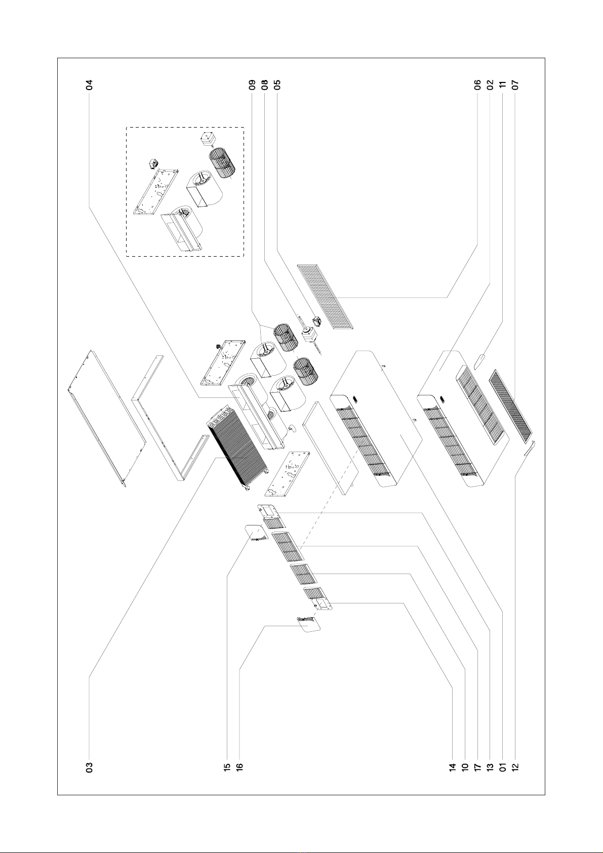
The motor is directly coupled to the fan(s) and
mountedonaflexible support and thesystemis
assembled to include a tray for collection of
condensation. Electrical connection with the
control panel is by rapid polarised insert.
The air filter is made of synthetic fibre and
mounted on a metal frame with a mesh net on
both sides. It can be extracted using the
unblockingflangesandatool. IntheFCandFCR
versions with casing, the air filter is supplied on
request.
The cover (F and FR versions) is made of zinc
plate and pre-painted in colour RAL 9002. It is
protected by transparent cling film to prevent
damageduringtransportationandinstallation. G
versionare alsoavailablewithacovercomplete
with frontal intake grille in plastic and air filter.
The air output grille comesinmodularform in
heat-resistant plastic in colour RAL 7032. The
right and left terminals include the site for the
control panel (F version) and the necessary
accessflapswhichhaveanexclusivetripclosing
mechanism. In locations where access to the
control panel is not allowed (public places,
schools etc.) the access points can be closed
using the appropriate screw with head cover.
The F version fan heaters come as standard
with space for the control panel on the right
side.
Thecontrolpanelisnotincludedinthestandard
fanheaterpackbecausetherearevariousdifferent
models both for mounting on the appliance and
for remote mounting on a wall:
-Basic control panel 1
consists of an on-off switch for starting and
turning off the fan heater, a manual 3-speed
selector and an 'on' indicator light.
-Basic control panel 2
consists of a manual selector for OFF/
SUMMER/WINTER,a3-speedmanualselector
and an 'on' indicator light.
The control panel is set up for connection of a
thermostat(suppliedseparately)whichmeans
that in the heating mode the fan is activated
only when the temperature of the water in the
heat exchanger exceeds a pre-set limit.
- Electronic thermostat 1
consists of an on-off switch for starting and
turning off the fan heater, a 3-speed manual
selector, and 'on' indicator light and a manual
SUMMER/WINTERselector.
The thermostat ensures automatic accurate
temperaturecontrolinheatingandconditioning
plants with 2 pipes. The thermostat regulator
switch enables temperatures of from 5°C to
35°Ctobe programmed. Thefanheater goes
offautomaticallywhen the desiredtemperatu-
re is reached.
- Electronic thermostat 2
consistsofamanualOFF/SUMMER/WINTER
switch, a 3-speed manual selector and an 'on'
indicatorlight.
The thermostat includes all the functions of
electronicthermostat1andinadditioncanbe
used with a 2-electrovalve control in 4-pipe
plants or 1 electrical resistance electrovalve
in 2-pipe plants. A minimum temperature
reading can also be included using an
appropriate connection (for use in winter
cycle).
- Microprocessor thermostat
Includes all the functions of the electronic
thermostats and in addition has automatic fan
speedselectionand summer/winter switch. A
2 electrovalve control is possible in 4-pipe
plants and 1 electrical resistance electrovalve
in 2-pipe plants. A minimum temperature
reading can also be included (for winter use)
and a device for activating the energy saving
function.
1.5 PACK CONTENTS
The fan heaters are supplied as standard in
recyclablecardboardpackagingwithexpanded
polystyreneorpre-shapedcardboardprotective
covering.
The pack contains this manual of technical
installation procedures, use and maintenance
as well as plastic fittings and screws for fixing
the filters in versions F-FR with covers.
1.6 OPTIONAL ACCESSORIES
Aswellasthecontentslistedabove,thefollowing
optional extras can be supplied:
- Basiccontrolpanel1(withbracketformounting
on the appliance or on the wall).
- Basiccontrolpanel2(withbracketformounting
on the appliance or on the wall).

pag. 5
- Electronic thermostat 1 (with bracket for
mounting on the appliance or on the wall).
- Electronic thermostat 2 (with bracket for
mounting on the appliance or on the wall).
- Microprocessor thermostat (with bracket for
mounting on the appliance or on the wall).
- Mechanicalthermostatforbasecontrolpanel 2.
- Mechanical thermostat for control panel with
electronic thermostat 1.
- Minimumtemperaturegauge for controlpanel
with electronic thermostat 2.
- Minimumtemperaturegauge for controlpanel
with microprocessor thermostat.
- 1 row supplementary battery for heating.
- Auxiliary condensation collection tray for use
with F - FC vertical versions.
- Pair of foot supports for F version with cover.
- Frontal grille support for F-FR versions with
cover.
- 90° air intake system for FC - FCR versions
with casing.
- 90° air output system for FC - FCR versions
with casing.
- Direct air output system for FC -FCR versions
with casing.
- Frontal air intake panel for FCR horizontal
version with casing.
- Lower air intake panel for FCR horizontal
version with casing.
- Lower/back air intake closure panel.
- Aluminium air intake grille with filter for FC -
FCR versions with casing.
- Aluminium air output grille with fixed slats for
FC - FCR versions with casing.
- Air filter for the built in versions FC - FCR.
- Valve kit for 3 row standard battery only, com-
plete with pipes and fittings.

pag. 6
562
A
1/2” G exit
220 48172
B
A
562
144
45
477
274
477
274
144
45
1/2” G entry
1/2” G exit
1/2” G entry
B
220 48
172
C
150
360
93
D
D
1.7 SIZE AND MASS
Mod. 100 200 300 400 600 800
A760 870 980 1.090 1.310 1.310
B440 550 660 770 990 990
C460 570 680 790 1.010 1.010
D644 754 864 974 1.194 1.194
Fig. 1
VERTICAL FRVERSION WITH COVER
HORIZONTAL FCVERSION WITH COVER

pag. 7
1.7 SIZE AND MASS
Fig. 2
Mod. 100 200 300 400 600 800
A480 590 700 810 1.030 1.030
B440 550 660 770 990 990
VERTICAL FC VERSION WITH CASING
HORIZONTAL FCR VERSION WITH CASING
220
142
B
A
525
144
45
477
274
1/2” G exit
1/2” G entry
525
A
1/2” G exit
477
274
14445
1/2” G entry
B
220
118
24 A+60

pag. 8
1.8 DETAILED VIEW - Vertical FRversion with cover
Fig. 3
modd.100-200

pag. 9
1.8 DETAILED VIEW - Horizontal FCversion with cover
Fig. 4
modd.100-200

pag. 10
1.8 DETAILED VIEW - Vertical FCOversion with casing
Fig. 5 modd.100-200

pag. 11
1.8 DETAILED VIEW - Horizontal FCR version with casing
Fig. 6
modd.100-200

pag. 12
Components
Vertical FRversion with cover (fig. 3)
01 coverwith grille
02 variationG withfrontalairintake grille
03 3 row heat exchange system
04 complete fan system
05 autotransformer
06 standardair filter
07 frontalair intakefilterorsupport
08 fanmotor
09 fan casing + fan
10 220mmgrille element
11 rightfront intakegrilleterminal
12 leftfront intakegrilleterminal
13 rightgrille terminal
14 leftgrille terminal
15 rightflap
16 leftflap
17 330mmgrille element
Components
Vertical FCOversion with casing (fig. 5)
03 3 row heat exchange system
04 complete fan system
05 autotransformer
08 fanmotor
09 fan casing + fan
Components
Horizontal FCversion with cover (fig. 4)
01 coverwith grille
02 variationG withfrontal intakegrille
03 3 row heat exchange system
04 complete fan system
05 autotransformer
06 standardair filter
07 frontalair intakefilterorsupport
08 fanmotor
09 fan casing + fan
10 220mmgrille element
11 rightfront intakegrilleterminal
12 leftfront intakegrilleterminal
13 rightgrille terminal
14 leftgrille terminal
15 rightflap
16 leftflap
17 330mmgrille element
Components
Vertical FCR version with casing (fig. 6)
03 3 row heat exchange system
04 complete fan system
05 autotransformer
08 fanmotor
09 fan casing + fan

pag. 13
1.9 TECHNICAL DATA TABLE 100 200 300 400 600 800
max. 2.830 4.130 5.640 7.050 9.770 12.330
med. 2.530 3.680 5.140 6.290 8.860 11.230
min. 2.220 3.210 4.670 5.230 7.480 10.580
Max water capacity 243 355 485 606 825 1.060
Max charge loss water 70 °C 1,50 3,00 7,30 11,45 23,50 33,00
max. 1.620 2.200 3.370 4.050 5.900 6.060
med. 1.450 1.830 3.070 3.640 5.270 5.610
min. 1.270 1.680 2.790 3.240 4.620 5.090
Max charge loss water 50 °C (E) kPa max. 1,03 2,27 6,45 8,90 22,25 26,50
max. 1.860 2.420 3.380 4.100 5.930 6.530
med. 1.710 2.240 3.160 3.800 5.510 6.270
min. 1.540 2.060 2.970 3.490 4.630 6.070
1 row battery water capacity 160 208 291 352 516 559
Max charge loss water 1 row battery 4,50 7,60 16,00 26,50 46,00 51,00
max. 1.150 1.630 2.730 3.110 4.660 5.140
med. 1.030 1.380 2.410 2.880 4.230 4.740
min. 880 1.270 2.190 2.630 3.870 4.360
max. 930 1.320 2.220 2.550 3.640 4.150
med. 830 1.110 1.940 2.180 3.220 3.670
min. 700 995 1.720 1.970 2.850 3.340
Max cooling water capacity 192 275 460 552 790 868
Max charge loss cooling water (E) 1,22 2,70 7,65 10,55 26,45 31,00
max. 210 340 450 560 760 1.000
med. 180 280 400 485 630 890
min. 150 240 340 434 540 780
Number of fans
max. 30,6 39,5 40,7 42,3 44,7 50,0
med. 27,7 34,9 37,4 39,4 41,8 48,1
min. 22,9 31,9 34,2 36,7 37,1 45,5
max. 39,1 48,0 49,2 50,8 53,2 58,5
med. 36,2 43,4 45,9 47,9 50,3 56,6
min. 31,4 40,4 42,7 45,2 45,6 54,0
230 V / 1 / 50 Hz
Max motor potential (E) 34 45 58 77 104 123
Max current absorption 0,15 0,20 0,25 0,34 0,46 0,59
Weight 17,0 19,0 22,0 24,6 28,8 30,2
(E) = Eurovent certified. Data refer to the following working conditions:
Summer cooling: outside air temperature: 27 °C b.s., 19 °C b.u.
Water temperature: intake 7 °C, outgoing 12 °C at max speed
Winter heating: outside air temperature: 20 °C
Water temperature: intake 70 °C,
∆
T 10 °C at max speed
(with intake water at 50 °C the same water capacity as for cooling at max speed)
Unit of mes.
Heat potential
(incoming water 70°C) W
l/h
kPa
Heat potential (E)
(incoming water 50°C) W
Heat potential for
supplementary 1 row battery W
l/h
kPa
Total cooling potential (E) W
Air capacity (E) m3/h
Sensitive cooling potential W
l/h
kPa
2
Noise levels dB (A)
Noise potential (E) dB (A)
n° 1
Electric power
W
A
kg

pag. 14
1.10 3 row standard battery potential heat output diagrams
Rese termiche - Mod. 100
0,5
1,0
1,5
2,0
2,5
3,0
3,5
4,0
4,5
0 100 200 300 400 500 600 700 800
Portata acqua (l/h)
Resa termica (kW)
20
30
40
50
60
70
Le rese temiche delgrafico corrispondono alla massima velocità. Per conoscere le rese
alle altre velocità moltiplicare i valori peri seguenti coefficienti:
V med 0,87
V min 0,77
∆
T = T
acqua entrante
- T
aria
Rese termiche - Mod. 200
0,5
1,5
2,5
3,5
4,5
5,5
6,5
100 200 300 400 500 600 700 800 900
Portata acqua (l/h)
Resa termica (kW)
20
30
40
50
60
70
Le rese temiche delgrafico corrispondono alla massima velocità. Per conoscere le rese
alle altre velocità moltiplicare i valori per i seguenti coefficienti:
V med 0,88
V min 0,79
∆
T = T acqua entrante - T aria
Heat output - Mod. 100
Theheatoutputfiguresinthegraphareformax.speed. Tocalculateoutputatotherspeeds,
multiplythevalues by thefollowing coefficients:
Heat output (Kw)
Water capacity (l/h)
T ingoing water – T air
Heat output - Mod. 200
Theheatoutputfiguresinthegraphareformax.speed. Tocalculateoutputatotherspeeds,
multiplythevalues by thefollowing coefficients:
Heat output (Kw)
Water capacity (l/h)
T ingoing water – T air

pag. 15
Rese termiche - Mod. 300
1,0
2,0
3,0
4,0
5,0
6,0
7,0
8,0
9,0
100 200 300 400 500 600 700 800 900
Portata acqua (l/h)
Resa termica (kW)
20
30
40
50
60
70
Le rese temiche delgrafico corrispondono alla massima velocità. Per conoscere le rese
alle altre velocità moltiplicare i valori per i seguenti coefficienti:
V med 0,92
V min 0,82
∆
T = T
acqua entrante
- T
aria
Rese termiche - Mod. 400
2,0
3,0
4,0
5,0
6,0
7,0
8,0
9,0
10,0
11,0
200 300 400 500 600 700 800 900 1000
Portata acqua (l/h)
Resa termica (kW)
20
30
40
50
60
70
Le rese temiche delgrafico corrispondono alla massima velocità. Per conoscere le rese
alle altre velocità moltiplicare i valori per i seguenti coefficienti:
V med 0,91
V min 0,83
∆
T = T acqua entrante - T aria
1.10 3 row standard battery heat potential diagrams
Heat output - Mod. 300
Theheatoutputfiguresinthegraphareformax.speed. Tocalculateoutputatotherspeeds,
multiplythevalues by thefollowing coefficients:
Heat output (Kw)
Water capacity (l/h)
T ingoing water – T air
Heat output - Mod. 400
Theheatoutputfiguresinthegraphareformax.speed. Tocalculateoutputatotherspeeds,
multiplythevalues by thefollowing coefficients:
Heat output (Kw)
Water capacity (l/h)
T ingoing water – T air

pag. 16
Rese termiche - Mod. 600
2,0
4,0
6,0
8,0
10,0
12,0
14,0
16,0
350 450 550 650 750 850 950 1050
Portata acqua (l/h)
Resa termica (kW)
20
30
40
50
60
70
Le rese temiche delgrafico corrispondono alla massima velocità. Per conoscere le rese
alle altre velocità moltiplicare i valori per i seguenti coefficienti:
V med 0,88
V min 0,78
∆
T = T
acqua entrante
- T
aria
Rese termiche - Mod. 800
2,0
4,0
6,0
8,0
10,0
12,0
14,0
16,0
400 500 600 700 800 900 1000 1100
Portata acqua (l/h)
Resa termica (kW)
20
30
40
50
60
70
Le rese temiche delgrafico corrispondono alla massima velocità.Per conoscere le rese
alle altre velocità moltiplicare i valori per i seguenti coefficienti:
V med 0,93
V min 0,86
∆T = T
acqua entrante
- T
aria
1.10 3 row standard battery heat potential diagrams
Heat output - Mod. 600
Theheatoutputfiguresinthegraphareformax.speed. Tocalculateoutputatotherspeeds,
multiplythevalues by thefollowing coefficients:
Heat output (Kw)
Water capacity (l/h)
T ingoing water – T air
Heat output - Mod. 800
Theheatoutputfiguresinthegraphareformax.speed. Tocalculateoutputatotherspeeds,
multiplythevalues by thefollowing coefficients:
Heat output (Kw)
Water capacity (l/h)
T ingoing water – T air

pag. 17
1.11 Diagrams for standard 3 row battery
charge loss for 10°C water
°C 40 50 60 70 80
K 0,88 0,86 0,84 0,82 0,8
To calculate charge loss at different
temperatures, multiply by coefficient K
FR-FC-FCO-FCR 100
0,3
0,4
0,5
0,6
0,7
0,8
0,9
1
1,1
1,2
1,3
1,4
1,5
1,6
1,7
80 90 100 110 120 130 140 150 160 170 180 190 200 210 220 230
Portata [kg/h]
∆P [kPa]
FR-FC-FCO-FCR 200
0,6
0,8
1
1,2
1,4
1,6
1,8
2
2,2
2,4
2,6
2,8
3
3,2
3,4
120 130 140 150 160 170 180 190 200 210 220 230 240 250 260 270 280 290 300
Portata [kg/h]
∆P [kPa]
Capacity (kg/h)
Capacity (kg/h)

pag. 18
1.11 Diagrams for standard 3 row battery
charge loss for 10°C water
°C 40 50 60 70 80
K 0,88 0,86 0,84 0,82 0,8
To calculate charge loss at different
temperatures, multiply by coefficient K
FR-FC-FCO-FCR 400
2
3
4
5
6
7
8
9
10
11
12
13
14
240 260 280 300 320 340 360 380 400 420 440 460 480 500 520 540 560 580 600
Portata [kg/h]
∆P [kPa]
FR-FC-FCO-FCR 300
1,5
2
2,5
3
3,5
4
4,5
5
5,5
6
6,5
7
7,5
8
8,5
9
200 220 240 260 280 300 320 340 360 380 400 420 440 460 480 500
Portata [kg/h]
∆P [kPa]
Capacity (kg/h)
Capacity (kg/h)

pag. 19
1.11 Diagrams for standard 3 row battery
charge loss for 10°C water
°C 40 50 60 70 80
K 0,88 0,86 0,84 0,82 0,8
To calculate charge loss at different
temperatures, multiply by coefficient K
FR-FC-FCO-FCR 600
4
6
8
10
12
14
16
18
20
22
24
26
28
30
300 350 400 450 500 550 600 650 700 750 800 850
Portata [kg/h]
∆P [kPa]
FR-FC-FCO-FCR 800
10
12
14
16
18
20
22
24
26
28
30
32
34
36
38
40
500 550 600 650 700 750 800 850 900 950 1000
Portata [kg/h]
∆P [kPa]
Capacity (kg/h)
Capacity (kg/h)
This manual suits for next models
6
Table of contents
Other Accorroni Heater manuals
Popular Heater manuals by other brands

U-Line
U-Line H-8022 manual

Smartgen
Smartgen HWP40N user manual

Dimplex
Dimplex XLS6N Installation and operating instructions

Dimplex
Dimplex MFP 051E Installation and operating instructions

Livington
Livington Handy Heater Deluxe Instructions for use

Roberts Gorden
Roberts Gorden Gordon-Ray RTH-75 Service instructions