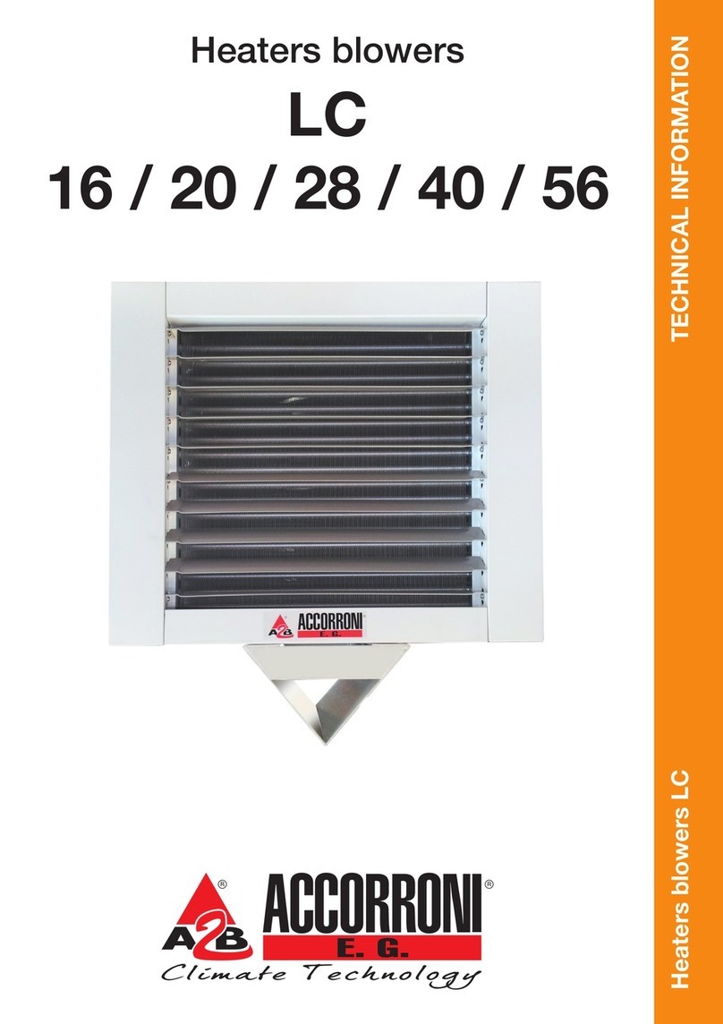
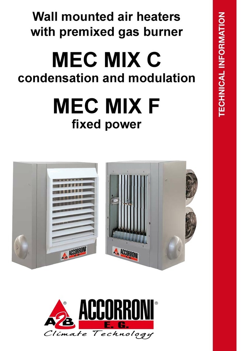
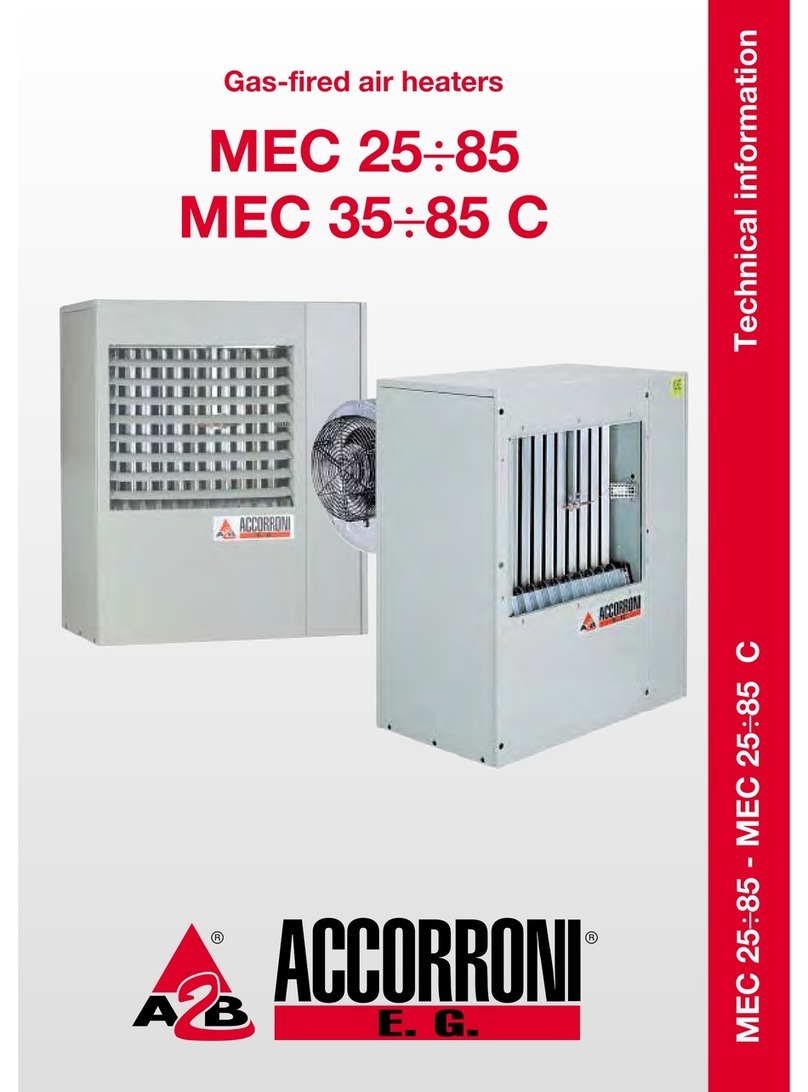
Accorroni GHIBLI 4-5-6 ELITE Manual

Technical Information
GHIBLI 4-5-6 ELITE
Gas-fired convective air heaters
GHIBLI 4-5-6 ELITE
Cod. 25619502IT - Rev. 0 - 20/03/2013


GAS FIRED CONVECTION HEATERS WITH FAN
GHIBLI SERIES
Models 4 - 5 - 6
Technical information
This manual is divided into three sections:
-SECTION 1 - GENERAL INFORMATION
It contains all the information relevant to the description of the heaters and their technical features
-SECTION 2 - TECHNICAL INFORMATION FOR THE INSTALLER
It contains all the instructions that the technical installer must comply with to ensure effective plant
operation
-SECTION 3 - USER OPERATING AND MAINTENANCE INSTRUCTIONS
The section is reserved for the user and contains all the information needed to use the appliance
correctly and to perform periodic tests
Important notes:
1- To use the appliance correctly and safely, the installer, the user and the service man, must comply
with what is indicated in this manual.
2- The word WARNING! is followed by information which, because of its importance, must be carefully
observed and for which non-compliance may damage the appliance and/or reduce operating safety.
3- The paragraphs written with bold characters contain important information, warnings or
recommendations which should be carefully considered.
4- The technical data, styling characteristics, components and accessories detailed in this manual are
not binding. A2B ACCORRONI E.G. S.r.l. reserves the right to make changes, at any time,
that are considered necessary to improve the product.
5- The legal references, standards and technical rules mentioned in this manual are presented merely
for the sake of information and should be considered valid as of the date this manual is printed, as
indicated on the last page. If new regulations or amendments to current laws go into effect, this will
not obligate A2B ACCORRONI E.G. S.r.l. in any way with regard to others.
6- A2B ACCORRONI E.G. S.r.l. is responsible for ensuring that its product conforms to the laws,
directives andconstruction standards in force at the time the product is sold. Knowledge and
compliance with legal regulations and standards regarding plant design, installation, operation and
maintenance are the exclusive responsibility of the designer, installer and user.
SUMMARY
SECTION 1 - GENERAL INFORMATION page
1. PRINCIPAL CHARACTERISTICS .......................................................................................... 4
1.1 Appliance classification ........................................................................................................... 4
1.2 Certification - EC marking ....................................................................................................... 4
1.3 Functional description ............................................................................................................. 4
1.4 Construction characteristics.................................................................................................... 5
1.5 Package contents ................................................................................................................... 5
1.6 Accessories supplied on request ............................................................................................ 5
1.7 Application .............................................................................................................................. 5
1.8 Dimensions ............................................................................................................................. 6
1.9 Wiring diagram........................................................................................................................ 7
1.10 Technical data table ................................................................................................................ 8
1.11 Exploded view ......................................................................................................................... 9

page 2
2. CONTROL AND SAFETY DEVICES .................................................................................. 12
2.1 Gas controller ....................................................................................................................... 12
2.2 Gas unit................................................................................................................................. 12
2.3 Fan thermostat...................................................................................................................... 12
2.4 Safety thermostat.................................................................................................................. 12
SECTION 2 - TECHNICAL INFORMATION FOR THE INSTALLER
3. PRECAUTIONS ................................................................................................................... 13
3.1 Gas safety regulations .......................................................................................................... 13
3.2 Related documents ............................................................................................................... 13
3.3 Transport and handling ......................................................................................................... 13
3.4 Data check ............................................................................................................................ 13
3.5 Using the instructions ........................................................................................................... 13
4. INSTALLATION .................................................................................................................... 13
4.1 Positioning instructions ......................................................................................................... 13
4.2 Air intake and flue exhaust ducts .......................................................................................... 14
4.3 Outside positioning of the flue gas exhaust terminal ............................................................. 15
4.4 Installation operations ........................................................................................................... 15
5. START-UP ........................................................................................................................... 18
5.1 Tests ..................................................................................................................................... 18
5.2 Ignition ................................................................................................................................... 19
5.3 Useful information ................................................................................................................. 19
6. GAS TYPE CHANGE .......................................................................................................... 20
6.1 Switching from gas in the second group to gas in the third group ........................................ 20
6.2 Switching from gas in the third group to gas in the second group ........................................ 20
7. OPERATING DEFECTS ...................................................................................................... 21
7.1 Preliminary tests ................................................................................................................... 21
7.2 Possible defects ................................................................................................................... 21
8. REPLACING PARTS ........................................................................................................... 23
8.1 Control equipment ................................................................................................................. 23
8.2 Fuse ...................................................................................................................................... 23
8.3 Gas solenoid valves .............................................................................................................. 23
8.4 Convection fan control thermostat ........................................................................................ 23
8.5 Safety limit thermostat .......................................................................................................... 23
8.6 Electrodes ............................................................................................................................. 24
8.7 Flue exhaust fan.................................................................................................................... 24
8.8 Convection fan ...................................................................................................................... 24
9. PERIODIC MAINTENANCE OPERATIONS....................................................................... 25
9.1 User information.................................................................................................................... 25
9.2 Yearly inspection ................................................................................................................... 25
SECTION 3 - USER OPERATING AND MAINTENANCE INSTRUCTIONS
10. START-UP ........................................................................................................................... 26
10.1 First firing and testing ............................................................................................................ 26
10.2 Tests ..................................................................................................................................... 26
10.3 Ignition ................................................................................................................................... 26
10.4 Shutdown .............................................................................................................................. 26
11. APPLIANCE MAINTENANCE ............................................................................................. 27
11.1 Routine maintenance to be performed by the user ............................................................... 27
11.2 Annual air heater inspection .................................................................................................. 27

page 3
FIGURE SUMMARY
Fig. no. page
1Dimensions ............................................................................................................................... 6
2Wiring Diagram .................................................................... - Ghibli Model 4 ........................... 7
3Wiring Diagram .................................................................... - Ghibli Model 5 ........................... 7
4Wiring Diagram .................................................................... - Ghibli Model 6 ........................... 8
5Exploded View ...................................................................... - Ghibli Model 4........................... 9
6Exploded View ...................................................................... - Ghibli Model 5 - 6 ................... 10
7Gas controller .......................................................................................................................... 12
8Fan thermostat ........................................................................................................................ 12
9Safety thermostat .................................................................................................................... 12
10 Positioning ............................................................................................................................... 14
11 Minimum maintenance distances............................................................................................ 14
12 Type C12 installation ............................................................................................................... 14
13 Type C52 installation ............................................................................................................... 15
14 Terminal protection grille ......................................................................................................... 15
15 Intake/exhaust duct ................................................................................................................. 16
16 Solution with duct doubling device........................................................................................... 16
17 Location of the doubling device in the wall............................................................................... 16
18 Coupling with the doubling device ........................................................................................... 16
19 Power supply cable connection............................................................................................... 18
20 Connecting more than one unit with a single external timer .................................................... 18
21 Control panel ........................................................................................................................... 19
22 Gas unit ................................................................................................................................... 20
23 Standard gas change .............................................................................................................. 21
24 Control equipment replacement .............................................................................................. 23
25 Gas unit coil replacement ........................................................................................................ 23
26 Fan thermostat replacement ................................................................................................... 23
27 Safety thermostat replacement ............................................................................................... 24
28 Electrode positioning ............................................................................................................... 24
29 Flue exhaust replacement ....................................................................................................... 24
30 Fan replacement .................................................................. - Ghibli Model 4 ......................... 24
31 Fan replacement .................................................................. - Ghibli Model 5 - 6 ................... 25
32 Cleaning the appliance ......................................................... - Ghibli Model 4 ......................... 25
33 Control panel ........................................................................................................................... 26

page 4
SECTION 1 - GENERAL INFORMATION
1. PRINCIPAL CHARACTERISTICS
1.1 APPLIANCE CLASSIFICATION
These appliance are defined as “Independent
gas-fired convection heaters incorporating a fan
to assist transportation of combustion air and
flue gases”.
In addition, they are classified according to
harmonised European standards EN 437 and
EN 1266 into:
category - according to the types of gas, at the
different supply pressures, that they can use;
type - according to the possible methods to
exhaust the combustion productions (see also
4.2.1).
1) Category II2H3+
the heater is suitable to use gas that belongs to
two families. The atmospheric burner can be fed
with gas from the second group (natural gas -
group H) and gas from the third group (butane
and propane at the two pressure ratings 28-30
and 37 mbar)
2) Type C12
The combustion circuit is sealed with respect to
the environment in which it is installed and the
combustion air supply and combustion product
exhaust lines are connected outside the room by
means of flues which pass directly through the
outside wall of the room.
3) Type C52
The combustion circuit is hermetically sealed with
respect to the environment in which it is installed
and the combustion air supply and combustion
product exhaust lines are connected outside the
room by means of separate ducts with terminals
which need not necessarily be adjacent to each
other. (In this case, a special accessory shall be
used which is supplied on request).
1.2 CERTIFICATION - EC MARKING
The Ghibli air heaters, as previously described
and classified, have obtained the "CE type test
certificate" in conformity with EEC Directive 90/
396 and with reference to the harmonised
European standard EN 1266. Attaching the CE
marking shown below also guarantees that the
appliance conforms with EEC directive 2006/95
("Low voltage") through the harmonised standard
EN 60335-1 and EEC directive 2004/108
("Electromagnetic compatibility") through the
standards EN 50081-1 and 50082-1.
It is important to point out that, to protect the end
user, attaching the CE marking means that the
manufacturer must submit a declaration of
conformity for the entire line of products with the
certified characteristics and performance ratings.
This is possible through the use, by the
manufacturer, of a Quality Assurance system.
The efficiency of that system is controlled by the
Organisation which issued the certification.
1.3 FUNCTIONAL DESCRIPTION
The Ghibli air heater consists basically of a heat
exchanger unit which exchanges heat between
the combustion products of a gas burner and the
air flow delivered by a fan.
The technology used to build the burner also
ensures very low emission of polluting NOx
(nitrogen oxides) for this category of appliance.
The fan takes in the room air which is then
heated as it passes through the heat exchanger.
The warm air is discharged directly into the
environment through the grille located at the top
of the appliance.
Fan operation is controlled by a thermostat: to
prevent cold air from entering the environment.
The fan begins operating shortly after the burner
has ignited. The fan runs for a short time after the
burner is extinguished, to allow the exchanger to
cool off gradually.
In case of malfunction or if the fan does not turn
on and the exchanger overheats, a safety
thermostat trips and cuts off the gas flow to the
burner.
The combustion products are exhausted
outdoors by a centrifugal fan installed after the
hermetically sealed combustion circuit. The
combustion chamber always has a lower
pressure with respect to the environment, thus
providing an additional safety feature.

page 5
Air heater operation is controlled by the built-in
room thermostat and by a digital timer that may
be supplied on request.
1.4 CONSTRUCTION CHARACTERISTICS
The casing is built with ivory-coloured, epoxy-
powder painted steel plate, with sides made with
black, heat-resistant nylon. The two air intake
and delivery grilles are located, respectively, at
the bottom and at the top of the casing.
The control panel is located on the front of the
appliance. This panel includes the following:
-on/off switch
-convection fan speed switch (models 5 and 6)
-reset switch for the burner control device
-lockout led
-heat request led
-room thermostat regulation dial
The rear of the appliance includes the following:
-the connector for the combustion air inlet and
combustion product exhaust ducts
-the holes to attach the appliance to the wall
-the entry with cable gland for the air heater
electric power supply
The following is installed inside the appliance:
-the combustion chamber and the finned heat
exchanger with flue gas exhaust fan located
after the heat exchanger.
-the atmospheric burner with ignition electrode
and flame detection electrode
-a tangential convection fan for Ghibli model 4
and a centrifugal type with double impeller and
central motor for Ghibli models 5 and 6
-the fan control thermostat and safety
thermostat
-the electric board including the burner control
device, the gas unit, the room thermostat and
related wiring
1.5 PACKAGE CONTENTS
The air heater is shipped with cardboard packing
with two polystyrene foam protection shells which
also contain:
-the intake and exhaust duct for walls up to 40
cm, complete with connector flange, ceramic
fibre gasket, attachment screws and wind
protection terminal
-gas conversion kit with label.
-the gas on-off valve
-a screwdriver to disassemble the casing
-this installation and servicing technical
information manual as well as warranty
documents
1.6 ACCESSORIES SUPPLIED ON REQUEST
In addition to the material described above, the
following accessories can also be supplied on
request:
-intake and exhaust duct, 100 cm
-intake and exhaust doubling device including
terminals, to be used with separate ducts Ø 60
mm, rigid or bendable (see point 4.2.1)
-protection grille for standard terminal
-digital timer kit
1.7 APPLICATION
The Ghibli gas heater is an independent
appliance designed to heat individual rooms.
This design solution is a good alternative to
traditional equipment, since it does not involve
costly installation work and allows heat to be
managed in a personalised manner, room by
room, only when it is needed. The Ghibli gas
heater is ideal for single-family dwellings, vacation
homes, offices, stores, laboratories.
It is particularly suitable for restructuring projects,
where a traditional system would require major
masonry work or involve exorbitant costs. The
Ghibli gas heater can also be added to an
existing system.
WARNING! It is important to verify that the
design and installation conform with current
standards.

page 6
1.8 DIMENSIONI E INGOMBRI
AB C Aspir./Scar. Gas
Ghibli 4 717 267 534 Ø 65 G 3/8"
Ghibli 5 - 6 807 366 624 Ø 65 G 3/8"
Fig. 1

page 7
1.9 WIRING DIAGRAM - Ghibli Model 4
Fig. 2
Al =External auxiliaries supply
Ac =Control equipment
Ea =Ignition electrode
Er =Flame detection electrode
Ev =Gas solenoid valve
Fr =RFI filter
Int =On-Off switch
M1-2-3 =Connection terminal boards
Me =Flue gas exhaust motor
Mv =Fan motor
Op =Bridge for auxiliaries (i.e.: timer)
R=Reset button
Sb =Lockout signal
Src =Heat request signal
T=Earth connection
Ta =Room thermostat
Ts =Safety thermostat
Tv =Fan thermostat
=Fuse, 2A
- - - - - =Connection to be made
=Series connection
Warning:
-Power should be supplied to the heater
via a switch with contact opening of at
least 3 mm.
-Observe the correct phase-neutral polarity
when connecting the single-phase, 230 V
~50 Hz power supply.
Me
N
L
Ts
Op
Mv
Ta
Tv
Ev
Ea
Er
Ac Src
Int
R
Sb
Fr
M2
M1
17
16
15
14
13
12
11
10
9
N
L
230 V ~
50 Hz
8
7
6
5
4
3
2
1
18
19
M3
Al
T
1.9 WIRING DIAGRAM - Ghibli Model 5
Fig. 3
Al =External auxiliaries supply
Ac =Control equipment
Co =Fan speed switch
Ea =Ignition electrode
Er =Flame detection electrode
Ev =Gas solenoid valve
Fr =RFI filter
Int =On-Off switch
M1-2-3 =Connection terminal boards
Me =Flue gas exhaust motor
Mv =Fan motor
Op =Bridge for auxiliaries (i.e.: timer)
R=Reset button
Sb =Lockout signal
Src =Heat request signal
T=Earth connection
Ta =Room thermostat
Ts =Safety thermostat
Tv =Fan thermostat
=Fuse, 2A
- - - - - =Connection to be made
=Series connection
Warning:
-Power should be supplied to the heater via a
switch with contact opening of at least 3 mm.
-Observe the correct phase-neutral polarity
when connecting the single-phase, 230 V ~
50 Hz power supply.
N
L
Ts
Op
Mv
Ta
Tv
Ev
Ea
Er
Ac Src
Int
R
Sb
Fr
M2
M1
17
16
15
14
13
12
11
10
9
N
L
230 V
~ 50 Hz
8
7
6
5
4
3
2
1
18
19
M3
Al
T
Co
common
I
II
Me
Fan motor 2 speed 3 speed
connections motor motor
Max. speed II
Med. speed II
Min. speed I I

page 8
1.9 WIRING DIAGRAM - Ghibli Model 6
Fig. 4
N
L
Ts
Op
Mv
Ta
Tv
Ev
Ea
Er
Ac Src
Int
R
Sb
Fr
M2
M1
17
16
15
14
13
12
11
10
9
N
L
230 V
~ 50 Hz
8
7
6
5
4
3
2
1
18
19
M3
Al
T
Co
common
I
II
Me
Al = External auxiliaries supply
Ac =Control equipment
Co =Fan speed switch
Ea =Ignition electrode
Er =Flame detection electrode
Ev =Gas solenoid valve
Fr =RFI filter
Int =On-Off switch
M1-2-3 =Connection terminal boards
Me =Flue gas exhaust motor
Mv =Fan motor
Op =Bridge for auxiliaries (i.e.: timer)
R=Reset button
Sb =Lockout signal
Src =Heat request signal
T=Earth connection
Ta =Room thermostat
Ts =Safety thermostat
Tv =Fan thermostat
=Fuse, 2A
- - - - - =Connection to be made
=Series connection
Warning:
-Power should be supplied to the heater
via a switch with contact opening of at
least 3 mm.
-Observe the correct phase-neutral polarity
when connecting the single-phase, 230 V
~50 Hz power supply.
1.10 TECHNICAL DATA TABLE Units Ghibli 4 Ghibli 5 Ghibli 6
Heat input (Hi)kW 3,72 4,83 5,52
kcal/h 3.200 4.150 4.750
Heat output (Hi)kW 3,35 4,37 4,91
kcal/h 2.880 3.760 4.220
Gas Natural gas G20 mc/h 0,39 0,51 0,58
consumption Butane G30 kg/h 0,29 0,38 0,44
(15 °C - 1.013 mbar) Propane G31 kg/h 0,29 0,37 0,43
Burner G20 p 20 mbar mbar 11,5 11,5 11,5
pressure G30 p 28-30 mbar mbar 27,8-29,8 27,7-29,8 27,7-29,8
(15 °C - 1.013 mbar) G31 p 37 mbar mbar 36,5 36,5 36,5
Injector size G20 mm 1,70 1,90 2,05
G30 / G31 mm 1,00 1,10 1,15
Air delivery Min. speed m3/h 110 180 240
Max. speed m3/h -240 300
Gas service connection “G 3/8
Air supply / Flue exhaust diameter mm 65
Fuse A2
Electrical supply 230 V ~ / 1 / 50 Hz
Electric power W47 80 102
Net weight kg 21 27 27

page 9
1.11 EXPLODED VIEW - Model Ghibli 4
Fig. 5

page 10
1.11 EXPLODED VIEW - Models Ghibli 5 and 6
Fig. 6

page 11
Legend of components Ghibli 4 (see fig. 5)
Pos Codice ......................................................... Description
01 45610001 ........................................ Casing Ghibli 5/6 Elite
02 45810002 .................................... Screw for casing fixing
04 45610004 ................................... Heat exchanger Ghibli 4
05 40170018 .................................................. Fan thermostat
07 45610008 .................................................. Burner Ghibli 4
08 45610009 ............................................. Burner Disk Ghibli
10 45960007 ................................ Flame detection electrode
11 45960008 ............................................... Ignition electrode
11 45610012 ....................................... Gas injector MET 1.70
12 45610313 ....................................... Gas injector LPG 0.95
14 45610014 .................................... Burner chamber gasket
15 45970012 ...................................... Knob room thermostat
16 45620015 .............................. Commands electrical board
18 45620017 ..................... Electric supply connection board
19 45810021 .............................................................. Gas tap
20 45960033 .......................................................... Gas valve
21 45960034 ........................................ Valve rectifier bridge
22 45960035 ................................................ Spool gas valve
23 45970020 ............................................... Room thermostat
25 45960216 ........................................................ Control box
27 45620026 ........................................ Flue gas exhaust fan
28 45610032 ........................... Exchanger/exhauster gasket
30 45610034 ..................................... Intake/exhaust terminal
31 45610035 .......................................... Intake/exhaust duct
32 45610036 .................................... Duct attachment gasket
33 45610037 .................................................... Tangential fan
34 45880506 ................................................ Tank of humidity
35 45880501 ................................. Plastic side dx Ghibli elite
36 45880502 ................................. Plastic side sx Ghibli elite
37 45610003 ............................................. Safety thermostat
38 45650211 .................................... Plate side dx Ghibli elite
39 45650212 .................................... Plate side sx Ghibli elite
40 45880503 ........................... Fixing plate side A Ghibli elite
41 45880504 ........................... Fixing plate side B Ghibli elite
42 45652522 ............................... Gas valve plate Ghibli elite
43 45652523 ....................... Plate for control box Ghibli elite
44 45880505 ..................................... Door control Ghibli elite
45 45611601 ................................................ Gas supply pipe
47 45970011 ........................... Internal electric wiring board
48 45619501 ..... Stricker plate of control panel Ghibli 4 elite
(*) Components missing in the design
*45610038 ..................................... Bronze friction bearing
*45960036 ............................. Kit of gas valve connection
Legend of components Ghibli 5 and 6 (see fig.6)
Pos Code description
01 45660001 ........................................ Casing Ghibli 5/6 Elite
02 45810002 .................................... Screw for casing fixing
04 45710004 ........................ Heat exchanger Ghibli 5/6 Elite
05 40170018 .................................................. Fan thermostat
07 45660008 ............................... Complete burner Ghibli 5/6
08 45710009 ....................................... Burner Disk Ghibli 5/6
10 45960007 ................................ Flame detection electrode
11 45960008 ............................................... Ignition electrode
12 45660013 ....................................... Gas injector MET 1.90
13 45660014 ....................................... Gas injector GPL 1.10
14 45610014 .................................... Burner chamber gasket
15 45970012 ...................................... Knob room thermostat
16 45670016 .............................. Commands electrical board
18 45620017 ..................... Electric supply connection board
19 45810021 .............................................................. Gas tap
20 45960033 .......................................................... Gas valve
21 45960034 ........................................ Valve rectifier bridge
22 45960035 ................................................ Spool gas valve
23 45970020 ............................................... Room thermostat
25 45960216 ........................................................ Control box
27 45670027 ........................................ Flue gas exhaust fan
28 45610032 ........................... Exchanger/exhauster gasket
30 45610034 ..................................... Intake/exhaust terminal
31 45610035 .......................................... Intake/exhaust duct
32 45610036 .................................... Duct attachment gasket
33 45710039 .................................................. Centrifugal fan
34 45880506 ................................................ Tank of humidity
35 45880501 ................................. Plastic side dx Ghibli elite
36 45880502 ................................. Plastic side sx Ghibli elite
37 45610003 ............................................. Safety thermostat
38 45650211 .................................... Plate side dx Ghibli elite
39 45650212 .................................... Plate side sx Ghibli elite
40 45880503 ........................... Fixing plate side A Ghibli elite
41 45880504 ........................... Fixing plate side B Ghibli elite
43 45652523 ....................... Plate for control box Ghibli elite
44 45880505 ..................................... Door control Ghibli elite
45 45611601 ................................................ Gas supply pipe
47 45970011 ........................... Internal electric wiring board
48 45719501 ..... Stricker plate of control panel Ghibli 4 elite
(*) Components missing in the design
*45960036 ............................. Kit of gas valve connection
*45652522 ............................... Gas valve plate Ghibli elite

page 12
2. CONTROL AND SAFETY DEVICES
2.1 GAS CONTROLLER
This device is housed in a heat-resistant and
shockproof plastic enclosure and is mounted on
the air heater electric board (fig. 7).
The control device operates on the ionisation
flame detection principle, using a special probe
on the burner.
The detection circuit must be fed with single-
phase 230 V ~50 Hz mains voltage. The
circuit is sensitive to the phase-neutral
polarity. If this is reversed, the device will
lock out within the safety time, even if the
flame has a regular shape (for special cases
consult our Technical Office).
2.2 GAS VALVE
The gas valve includes two, direct operation
solenoid valves with class B closing devices
(maximum pressure 50 mbar) and a pressure
regulator. The die-cast aluminium casing is
equipped with 3/8 RP threaded gas inlet and
outlet connections and two inlet and outlet
pressure test points. The gas valve is also
equipped with an inlet filter (fig. 22).
2.3 FAN THERMOSTAT
This thermostat controls fan operation, making
it start when the exchanger has reached the
rated operating temperature and stopping it
when the exchanger has adequately cooled.
The thermostat is attached to a threaded support,
located on the exchanger (fig. 8).
2.4 SAFETY THERMOSTAT
The thermostat is designed to interrupt burner
operation when the air temperature in the air
heater reaches a set value, i.e. when the
exchanger overheats due to insufficient air flow
or a fan malfunction. The thermostat enclosure
uses a special support to attach to the front
shield of the appliance (fig. 9).
Fig. 7
GASCONTROLLER
Fig. 9
SAFETYTHERMOSTAT
Thermostat
Electric
connection
Fig. 8
FAN THERMOSTAT
Threaded attachment
Electric connection

page 13
SECTION 2
TECHNICAL INFORMATION FOR THE INSTALLER
3. PRECAUTIONS
3.1 GAS SAFETY REGULATIONS
The law requires all gas appliances to be
installed by competent persons in accordance
with the regulations. Failure to install
appliances correctly may lead to prosecution.
It is in your own interests and that of safety to
ensure compliance with the law.
3.2 RELATED DOCUMENTS
Notwithstandingtheirlimited scope, the appliances
should be installed in accordance with the relevant
provisions of the following regulations:
UNITED KINGDOM
Gas Safety (Installation and Use) Regulations
1984 and BS 6891: 1988. Due account should
be taken of any obligations arising from the
Health and Safety at Work etc Act 1974, the
current Building Regulations, the current I.E.E.
Regulations and other relevant codes of practice.
IRELAND
I.S.3212: 1987, ICP 4, I.S.327. Due account
should be taken of any obligations arising from
the current Building Regulations, the current I.E.E.
Regulations and other relevant codes of practice.
3.3 TRANSPORT AND HANDLING
The air heater is supplied with standard cardboard
packing with two polystyrene foam shells. The
packed appliance can be handled by hand or
with a fork-lift truck, making sure to observe the
instructions reported on the box indicated by the
special graphic symbols.
When delivered, check that no visible damage
on the packing and/or on the appliance has
occurred during transport. If damage is noted,
immediately submit a claim to the shipping agent.
When removing the air heater from the packing,
do not damage the cardboard. The assembly
template to be used to make the holes on the wall
in the room is printed on that cardboard. Check
that the packing includes the appliance but also
all the parts indicated in point 1.5. Place the
material and the documents in a protected area.
3.4 DATA CHECK
Check that the heater and its technical
characteristics match what is indicated by the
drawings or other documents.
The type of gas for which the heater has been
designed and the supply pressure are found
on the exterior of the packing and on a special
label located on the inside of the appliance.
WARNING! If the type gas for which the
appliance has been designed is different
from the one being used, the conversion
operation must be carried out by skilled
technical personnel.
3.5 USING THE INSTRUCTIONS
WARNING! When installing or working on
the appliance, comply with all the instructions
given in this manual. Changes to any type of
connection and non-compliance with these
instructions will immediately invalidate the
warranty and release the manufacturer from
all responsibilities.
4. INSTALLATION
4.1 POSITIONING INSTRUCTIONS
Before carrying out any installation operations,
make sure that the following conditions are
satisfied regarding the position where the air
heater will be installed:
a) the appliance with standard accessories ,
must be installed on an external wall to ensure
that the it operates correctly.
The appliance can also be installed on other
walls by using a special kit which splits the
flue from the air intake. This is known as a
doubling device (see point 4.2.1).
b) it must be possible to provide a gas supply to
the selected point as well as a single-phase
230 Volts ~ 50 Hz power supply line
c) the position must be suitable to distribute the
air correctly into the room and the air flow
should not be obstructed by obstacles such
as furniture or drapes
d) the appliance must be installed at a minimum
of 10 cm from the floord so that the convection
fan can take in air correctly and thus ensure
optimal circulation of air on the exchanger. Do
not install the base of the appliance at a height
of more than 50 cm from the floor, since this
would lead to a non-uniform distribution of the
warm air and thus waste fuel

page 14
e) if the appliance is installed under a window or
under a shelf, make sure that the sill or the
shelf does not obstruct the flow of warm air;
it is recommended that a distance of at least
20 cm is maintained. For this reason and to
make maintenance easier, the air heater
should not be installed inside niches or in
positions where it is difficult to access. The
clearances indicated in fig. 11 should be
observed.
4.2 AIR INTAKE AND FLUE EXHAUST DUCTS
WARNING! The material used to build the
external wall and any covering (wood, plastic)
must not be sensitive to the heat generated
by the flue gas exhaust duct. If it is heat
sensitive, the passage hole must be
protected with insulation that insulates the
wall or the covering.
4.2.1 Type definition
As already mentioned in point 1.1, the Ghibli air
heatercan be installed with different configurations
of the air intake and combustion product exhaust
duct(s) and these different solutions constitute
the definition of "type" according to the current
standards:
-Type C12 (standard supply)
The combustion circuit is hermetically sealed
with respect to the environment in which the air
heater is installed. The intake/exhaust duct
passes directly through the external wall of the
room. This is the standard configuration supplied
(fig. 12).
-Typr C52 (with accessories on request)
The combustion circuit is sealed with respect to
the environment in which the air heater is installed.
The ducts are separated and both are connected
to the outdoors, but their terminals need not be
adjacent to each other (fig. 13).
WARNING! Also in the second solution (Type
C52), the intake and exhaust ducts, including
the relative accessories, are considered by
the standards to be integral parts of the air
heater. Therefore, they must be requested
from the manufacturer.
In both the cases described above the length of
the ducts must always respect the limits indicated
in the next point.
Fig. 12
TYPE C12 INSTALLATION
(standard supply)
Air intake / flue gas
exhaust duct
External terminal
Fig. 10
POSIZIONAMENTO
10-15 cm
min. 20 cm
MINIMUM MAINTENANCE DISTANCES
Fig. 11
TOP VIEW
60 cm 30 cm

page 15
4.2.2 Duct length limits
If the duct passes directly through the external
wall, and if that wall has a thickness of more than
40 cm, an intake/exhaust duct with a length of 1
metre can be supplied on request. If the appliance
is installed with separated ducts, using the special
accessory, the length of the ducts must not be
greater than 6 metres, considered as the sum of
the layout of both ducts (for example: 3 m intake
+ 3 m exhaust, etc.), to ensure correct operation.
It should be remembered that a bend is
equivalent to a straight segment of about 50 cm.
If the exhaust duct layout is exposed to low
temperatures, prevent condensation from
forming by using suitable insulation on that duct.
4.3 OUTSIDE POSITIONING OF THE FLUE
GAS EXHAUST TERMINAL
The position of the flue gas exhaust terminal and
its distance from windows, ventilation openings,
etc. must comply with what is prescribed by the
current standards.
If the air heater is installed in rooms on the ground
floor and the exhaust faces sidewalks at the level
of pedestrians, a special protection grille must be
applied, which is supplied on request (fig. 14).
4.4 INSTALLATION OPERATIONS
Set up the gas and electricity supply lines based
on the installation design.
4.4.1 Air heater wall-mounting preparations
(appliance with standard supply -
Installation Type C12)
Once the position and the height of the appliance
from the ground has been determined, use the
wall template from the cardboard packing to
indicate the positions of the holes to be made
(three holes to attach the appliance with an Ø 8
mm bit for expansion bolts, one hole for the
intake/exhaust duct with special hole cutter Ø 70
mm, to be made as perpendicular as possible to
the direction of the wall).
The template also indicates the positions of the
electric power supply cable and gas feeder pipe
entries.
4.4.2 Mounting the intake/exhaust duct
(appliance with standard supply -
Installation Type C12)
The intake/exhaust duct, supplied for walls up to
40 cm, consists of an aluminium pipe with
connector flange and an external terminal. Mount
the duct in the sequence described below:
Fig. 14
TERMINALPROTECTIONGRILLE
Grille
TYPE C52 INSTALLATION
Fig. 13
SIDE VIEW
TOP VIEW
Using the doubling device (supplied on
request), it is possible to create different
configurations of the air intake and flue gas
exhaust ducts, within specified limits. The
external terminals are not required to be
adjacent to each other.

page 16
a) precisely measure the thickness of the wall.
This measurement corresponds to the
distance between the flange and the point in
which the duct must be cut (fig. 15)
b) use a hack saw to cut the aluminium duct to
the specific measurement. Trim off any burrs
using a file
c) insert the duct into the appliance using the
special gasket and tighten it with the three
screws supplied with the kit.
WARNING! The duct can only be connected
in one direction; do not force the pipe if
resistance is felt. Note the position of the
pipe on the flange and turn it in the correct
position, if necessary.
4.4.3 Air heater wall-mounting preparations
and duct installation (appliance with
accessories for separate intake and
exhaust ducts - Installation Type C52)
Unlike the previous solution, to mount the duct
doubling device a recessed housing must be
created in the wall and possibly some chases to
indicate the duct layout (fig. 16).
Therefore, by positioning the cardboard template,
the centre of the appliance intake/exhaust fitting
must be traced on the wall. The centre of the
similar doubling device fitting must be in the
same position.
Create the depression in the wall for the doubling
device and make the necessary chases to house
the ducts, whether or not they are the rigid or the
Fig. 15
INTAKE / EXHAUST DUCT
(Type C12 - standard supply)
Terminal
Air intake and flue
gas exhaust duct
Wall thickness
Attachment
screw
Fig. 17
LOCATION OF THE DOUBLING DEVICE
IN THE WALL (top view)
WARNING!
(Side flush with wall)
Fig. 18
COUPLING WITH THE DOUBLING DEVICE
Aluminium
flange
O-Ring gasket
Screw
Doubling device
Fig. 16
SOLUTION WITH DUCT DOUBLING DEVICE
FLUE GAS
AIR INLET

page 17
bendable type in stainless steel. Connect the
ducts to the doubling device using metal clamps
and tighten them to ensure a good seal on the
fitting. With the doubling device connected in
this manner, place it in the housing and block it
into position using cement mortar.
Make sure to respect the position indicated
in fig. 17, so that only the circular fitting
projects from the finished wall, while the
interior of the doubling device is flush with
that wall.
WARNING! The seal of the connector between
the doubling device and the appliance is
created by a special gasket (fig. 18). Make
sure that the wall on which the air heater is
installed is perfectly flat, so that the
subsequent attachment of the appliance does
not change the coupling.
Assemble the ducts in the chases up to the
relative external terminal, carefully checking any
joints (if a rigid tube is used make sure that the
special unions and gaskets are mounted
correctly).
WARNING! It is recommended to insulate the
duct by using insulating material that is
suitable for the temperatures generated (for
example,glass fibre mattress for temperatures
up to 200°C), to prevent condensation from
forming inside the duct and/or to avoid cracks
in the plaster due to the high temperature. At
the end of the previous operations close the
chases, making sure that the cement mortar
completely covers the ducts and that there
are no empty spaces.
Place the previously used template on the wall,
centering the position of the intake/exhaust fitting
onto the corresponding centre of the walled
doubling device, and mark the position of the
three holes to attach the appliance. The holes
should be drilled using an Ø 8 mm bit for
expansion bolts.
To adapt the intake/exhaust fitting of the
appliance to the coupling with the doubling device
connector, do the following operations:
a) remove the three screws inserted in the fitting
on the appliance (they will not be used again)
b) mount the aluminium flange Ø 92 mm,
inserting the ring gasket and attaching it on
the appliance fitting using the three screws
supplied with the kit. Check that the ring
gasket fits correctly into its housing (fig. 18).
4.4.4 Appliance wall mounting
a)Appliance with standard supply -
Installation Type C12
Liftthe appliance and, putting the intake/exhaust
duct at the beginning of the hole, push it toward
the wall until contact is made.
Adjust the position of the appliance and attach
it with the expansion screws that were
previously inserted into the wall. On the
exterior, check that the intake/exhaust duct
ends flush with the wall.
Insert the external wind protection terminal on
the duct and mark the position of the hole for
the expansion bolt to be drilled in the wall (fig.
15). After drilling the hole, re-insert the terminal
and attach it permanently, checking its stability.
b)Appliance with accessories for separate
intake and exhaust ducts - Installation
Type C52
Lift the air heater and slowly bring it closer to
the wall until coupling the two intake/exhaust
connectors located on the doubling device
and on the appliance.
Making sure not to change the coupling
described above, adjust the position of the
appliance and attach it using the expansion
screws that were previously inserted into
the wall.
In both cases described above, it is
recommended to use two persons to lift and
position the air heater to avoid any possible
damage to the wall or the appliance.
4.4.5 Gas connection
Mount the gas on-off valve supplied with the
appliance using the special gasket. Connect the
gas supply line to the valve which is equipped
with a female threaded attachment G 3/8".
WARNING!: The valve must be located in a
position that can be easily accessed by the
user.
Check the seal on the gas piping and make sure
that it was created in conformity with the current
standards regarding gas installations.
4.4.6 Electrical connections
Ensure that a single-phase, 230 V ~ 50 Hz
electric power supply is available.
The appliance must be properly insolated by
means of an omnipolar circuit-breaker with

page 18
an adequate rating to be used as a general
switch to turn off the appliance(s).
Connect the power supply cable to the phase,
neutral terminals and to the earth connection of
the appliance. Insert the power supply cable
through the special cable gland, making sure to
cut the wires so that the yellow/green earth cable
is slightly longer than the other two.
This precaution, in case of accidental
detachment, allows the earth cable to be the last
connection to be removed (fig. 19).
Comply with the phase/neutral polarity,
otherwise the control equipment will gene-
rate a safety lock out.
THESE APPLIANCES MUST BE EARTHED.
4.4.7 Using a timer (the kit is supplied on
request)
To operate the air heater automatically at
predetermined hours, it is possible to install a
digital timer on the appliance, even after the
appliance has already been installed. The timer
is supplied on request as an assembly kit.
4.4.8 Connecting more than one unit with a
single external timer
To operate several appliances with just one
timer follow the diagram given in fig. 20 to avoid
malfunctions of the entire installation.
To complete this special connection, use a
normally open contact relay with an adequate
rating. Terminals 3 and 4 will be connected to the
terminal board of the appliances, after having
removed the existing bridge.
5. START-UP
WARNING! The appliance initial start-up
operations and tests must be performed by
skilled technical personnel.
5.1 TESTS
5.1.1 Before starting the air heater, make sure
that all the current provisions and standards
relevant to the installation of these appliances
have been observed. Pay particular attention to
the correct positioning of the combustion
product exhaust terminal.
5.1.2 Make sure that the single-phase, 230 V ~
50 Hz electric power supply and the earth wire
are connected to the special air heater terminals.
The phase conductor must be connected to the
terminal marked with the letter "L", otherwise the
control equipment will generate a safety lockout.
5.1.3 Check that the gas injector mounted on
the burner corresponds to what is indicated for
the type of gas to be used (table on page 11).
WARNING! The appliance are delivered
already set in the factory to use natural gas
G20, with a supply pressure of 20 mbar.
Instead, if gas from the third group is used
(G30 - G31), first carry out the operations
described in point 6.1.
5.1.4 Check that the gas on-off valves on the
meter and on the air heater are open. Make sure
that the air inside the gas supply piping has been
purged.
Fig. 20
4
3
1st heater 2nd heater
4
3
nth heater
n
2
1
n
2
1
Relay
with n
contacts
timer
switch
Neutral
Phase
4
3
Fig. 19
POWER SUPPLY CABLE CONNECTION
Brown
Yellow / Green
Blue
Table of contents
Other Accorroni Heater manuals