Acculab ATL-224 User manual

98648-015-55
Operating Instructions
ACCULAB ATILON
Electronic Analytical and Precision Balances

3Warnings and Safety Precautions
4Getting Started
5Installation
11 Operation
11 Display and Operating Elements
12 Basic Weighing Function
14 Calibration/Adjustment
17 Configuration (Operating Menu)
17 Functions of the Keys during Configuration
18 Menu Navigation; Example: Setting the Language
19 Parameter Settings: Menu
20 Parameter Settings: Overview
24 Input: ID Number, Date and Time
26 Application Programs
27 Counting
29 Weighing in Percent
31 Calculation
33 Animal Weighing/Averaging
35 Net-total Formulation
37 Totalizing
39 Density Determination
41 Mass Unit Conversion
2
Contents
44 ISO/GLP-compliant Printout/Record
46 Data Interface
47 Troubleshooting Guide
48 Care and Maintenance
49 Recycling
50 Overview
51 Specifications
55 Accessories
56 C-Marking
57 Declaration of Conformity
58 Confirmation of an EC Type-Approval Certificate

3
Safety
§To prevent damage to the equipment, please read these
operating instructions carefully before using the balance.
!Do not use this equipment in hazardous areas.
!The balance may be opened only by trained service
technicians.
!Disconnect the balance from power before connecting or
disconnecting peripheral devices.
!If you operate the balance under ambient conditions
subject to higher safety standards, you must comply with
the applicable installation regulations.
!Exposure to excessive electromagnetic interference can
cause the readout value to change. Once the disturbance
has ceased, the instrument can be used again in
accordance with its intended purpose.
Make sure that no liquid enters the equipment housing;
use only a slightly moistened cloth to clean the balance.
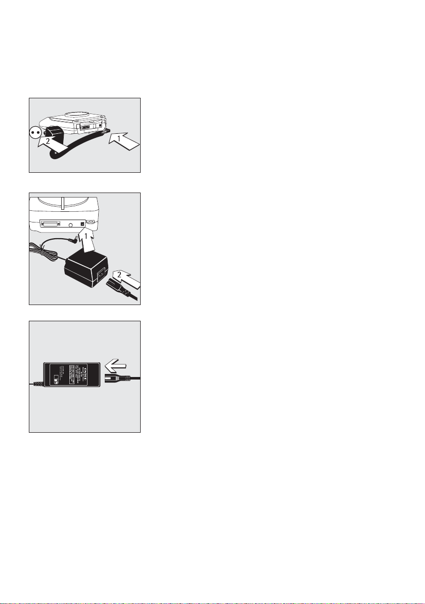
Installation
!Make sure the voltage rating printed on the power supply
is identical to your local line voltage.
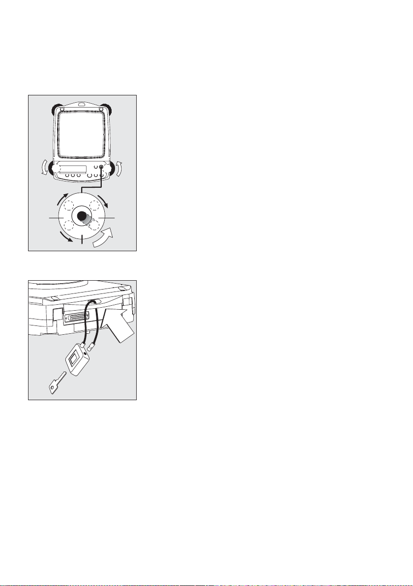
– Proceed with extreme caution when using pre-wired
RS-232 connecting cables, as the pin assignments may
not be compatible with Acculab equipment. Before
connecting the cable, check all pin assignments against
the cabling diagrams and disconnect any lines that are
assigned differently.
!If there is visible damage to the equipment or power cord,
disconnect the equipment from power and lock it in a
secure place to ensure that it cannot be used for the time
being.
– Connect only Acculab accessories, as these are optimally
designed for use with your Atilon balance. The operator shall
be solely responsible for installation and testing of any modifi-
cations to Acculab equipment, including connection of cables
or equipment not supplied by Acculab. On request,
Acculab will be happy to provide information on operating
specifications (in accordance with the Standards for defined
immunity to interference).
$Do not open the balance housing. If the seal is broken, this
will void all claims under the manufacturer’s warranty.
$If you have any problems with your balance, contact your
local customer service center.
Symbols
The following symbols are used in these instructions:
§indicates required steps
$indicates steps required only under certain conditions
> describes what happens after you have performed a
particular step
– indicates an item in a list
!indicates a hazard
Warnings and Safety Precautions

4
Storage and Shipping Conditions
– Do not expose the balance to extreme temperatures,
moisture, shocks, blows or vibration.
Unpacking the Equipment
§After unpacking the equipment, please check it immediately
for any external damage.
$If you detect any damage, proceed as directed in the
chapter entitled “Care and Maintenance,” under “Safety
Inspection.”
$Save the box and all parts of the packaging for any future
transport. Disconnect all cables before packing the balance
for shipping.
Equipment Supplied
– Balance
– Weighing pan
– Pan support (only for models with a round weighing pan)
– AC adapter
Additional equipment supplied with models
ATL-224, -124:
– Sliding-door draft shield
– Drip/breeze ring
– Draft shield base plate
Additional equipment supplied with models
ATL-623, -423, -153:
– Round glass draft shield with cover
Getting Started
Installation
Choose a location that is not subject to the following
negative influences:
– Heat (heater or direct sunlight)
– Drafts from open windows and doors
– Excessive vibration during weighing
– Excessive moisture
Conditioning the Balance
Moisture in the air can condense on cold surfaces
whenever the equipment is moved to a substantially
warmer place. To avoid the effects of condensation, allow
the balance to sit for 2 hours, at room temperature, before
plugging into AC power.
Seal on Balances Verified for Use in Legal
Metrology in the EU*:
For instruments of accuracy class K, EU legislation
requires that a control seal be affixed to verified balances.
The control seal consists of a sticker. If the seal is broken,
the verification becomes null and void and the balance
must be re-verified.
* Including the Signatories of the Agreement on the
European Economic Area

Installation
Setting Up the Balance
Instruments with sliding-door draft shield:
§Place components inside the chamber in the following order:
– Draft shield base plate
– Drip/breeze ring
– Pan support
– Weighing pan
Instruments with a round glass draft ring:
§Position the components listed below in the order given:
– Place the lower lid on the balance with the raised edge facing upwards
– Pan support
– Weighing pan
– Glass draft ring
– Place the upper lid on the draft shield ring with the raised edge facing downwards
Instruments with a round weighing pan
§Position the components listed below in the order given:
– Pan support
– Weighing pan
Instruments with a rectangular weighing pan:
§Place the weighing pan on the balance
5

Connecting the Balance to AC Power/Safety Precautions
Use only original Acculab AC adapters. For use within
– Europe: part no. 6971412
– U.S./Canada: part no. 6971413
§1) Connect the angle plug to the balance
§2) Connect the AC adapter to the wall outlet (mains)
AC Adapter with Country-specific Power Cord
Some models come with separate country-specific power cords for the
AC adapter.
§1) Connect the angle plug to the balance
§2) Select the power cord for your area and connect it to the AC adapter
§3) Plug the power cord into the wall outlet (mains)
Use an original Acclulab AC adapter with a wide input voltage range
$(100 to 240 V~), order no. 6971966, and replaceable power cord:
6900900 (Europe) 6900905 (AUS)
6900901 (US/CDN) 6900902 (ZA)
6971945 (UK) 6971977 (Argentina)
6971973 (India) 6971978 (China)
6971980 (Denmark) 6971975 (Israel)
6971776 (Italy)
Safety Precautions
Plug-in AC Adapter 6971412/6971413:
The AC adapter rated to Class 2 can be plugged into any wall outlet without
additional safety precautions.
Benchtop AC Adapter 6971966:
The AC adapter rated to Class 1 can be plugged into any wall outlet without
additional safety precautions.
The ground terminal is connected to the
balance housing, which can be additionally grounded for operation.
The data interface is also electrically connected to the balance housing (ground).
6

7
NOTE: This equipment has been tested and found to
comply with the limits pursuant to part 15 of FCC Rules.
These limits are designed to provide reasonable protection
against harmful interference. This equipment generates,
uses and can radiate radio frequency energy and, if not
installed and used in accordance with these instructions,
may cause harmful interference to radio communications.
For information on the specific limits and class of this
equipment, please refer to the Declaration of Conformity.
Depending on the particular class, you are either required
or requested to correct the interference.
If you have a Class A digital device, you need to comply
with the FCC statement as follows: “Operation of this
equipment in a residential area is likely to cause harmful
interference in which case the user will be required to
correct the interference at his own expense.”
If you have a Class B digital device, please read and follow
the FCC information given below:
“However, there is no guarantee that interference will not
occur in a particular installation. If this equipment does
cause harmful interference to radio or television reception,
which can be determined by turning the equipment off and
on, the user is encouraged to try to correct the interference
by one or more of the following measures:
– Reorient or relocate the receiving antenna.
– Increase the separation between the equipment and
receiver.
– Connect the equipment into an outlet on a circuit different
from that to which the receiver is connected.
– Consult the dealer or an experienced radio/TV technician
for help.”
Before you operate this equipment, check which FCC class
(Class A or Class B) it has according to the Declaration of
Conformity included. Be sure to observe the information of
this Declaration.

8
Connecting Electronic Peripheral Devices
§Make sure to unplug the balance from AC power before you connect or disconnect
a peripheral device (printer or computer) to or from the interface port.
Warmup Time
To ensure accurate results, the balance must warm up before operation
as follows:
– Models ATL-153 and ATL-822: 2 hours
– All other models: 30 minutes
Only after this time will the instrument have reached the required operating
temperature.
Using Verified Balances in Legal Metrology in the EU*:
$Make sure to allow the equipment to warm up for at least 24 hours after initial
connection to AC power or after a relatively long power outage.
Operation Outside the Temperature Range
!Operating the balance beyond the temperature range of +10…+30°C
(50°…86°F). Differences from the specifications listed in the chapter on
“Specifications” are possible.
* Including the Signatories of the Agreement on the European Economic Area

9
Below-Balance Weighing
A port for a below-balance weighing hanger
is located on the bottom of the balance.
$Below-balance weighing is not permitted in legal metrology.
§Open cover plate on the bottom of the balance.
Important: set the balance on its side to access the cover plate. DO NOT turn the
balance upside-down.
§Using the built-in hook 1: Attach the sample (e.g., using a suspension wire)
to the hanger.
$Install a shield for protection against drafts if necessary.
1

Leveling the Balance
Purpose:
– To compensate for unevenness at the place of installation
Always level the balance again any time after it has been moved to a different
location. Only the 2 front feet are adjusted to level the balance.
§Retract the two rear feet (only on models with a rectangular weighing pan).
§Turn the 2 front feet as shown in the diagram until the air bubble is centered
within the circle of the level indicator.
> In most cases this will require several adjustment steps.
§On models with a rectangular weighing pan: Lower the 2 rear feet until they
touch the surface on which the balance rests.
Anti-theft Locking Device
§To secure the balance at the place of installation, fasten a chain or a lock to the
lug located on the rear panel of the balance.
$Anti-theft locking device (chain and lock): order number LC-1
10
R
L
L
R
R
L

11
Overview of Display Elements
Operation
1
2
3
4
5
6
12
11
10
9
8
7
ATILON
ZERO
TARE
PRINT
ON/OFF
ENTER
MENUECLEAR CAL
Pos. Designation
1 Weight unit
2 Menu level indicator
3 Symbol: “GLP printing mode active”
4 Symbol: “Printing mode active”
5 Symbol: “Application program active”
6 Calculated-value indicator (i.e., not a weight value)
7 Symbol: Gross or net value
8 Symbols for active application
(W, Z, L, V, R, A, C)
9 Symbol: Calibration/adjustment function
10 Symbols for zero range
Pos. Designation
11 Busy symbol: command is being processed (for example,
“Wait for stability icon); after you turn on the power,
Awill be displayed until you press a key
12 Weight value displayed in selected weight unit
Symbols:
<< Save settings and exit the operating menu
< One menu level higher
V Scroll through menu items
> Next item on current menu level
↵Select a parameter setting
Overview of Operating Elements
Pos. Designation
1 On/off
2 Level indicator
3 Start calibration/adjustment routine
4 Data output:
Press this key to send readout values to the built-in data
interface.
5 Taring
Pos. Designation
6 Start an application program
7 Open the operating menu | Select an application program
8 Clear
This key is generally used to cancel functions:
– Quit application program
– Cancel calibration/adjustment routine |
Exit the operating menu
8
7
6
1
2
3
4
5

12
Features
– Taring the balance
– Printing weights
Preparation
§Switch on the balance:
Press (ON/OFF)
§Tare the balance, if necessary:
Press (TARE)
$If necessary, change the configuration settings:
See the chapter entitled “Configuration”
$If desired, load the factory settings:
See the chapter entitled “Configuration”
Additional Functions
$Switching off the balance:
Press (ON/OFF)
$Balance in standby mode:
the current time is displayed
Using Verified Balances as Legal Measuring
Instruments in the EU*:
The type-approval certificate for verification applies only to
non-automatic weighing instruments. For automatic
operation with or without auxiliary measuring devices, you
must comply with the regulations applicable to the place of
installation.
§Before using the balance as a legal measuring instrument,
calibrate and adjust it at the place of use using the built-in
motorized calibration weight; for details, see
“Calibration/Adjustment” in this chapter.
$
The temperature range (°C) indicated on the verification
label must not be exceeded during operation.
* Including the Signatories of the Agreement on the
Eruopean Economic Area
Basic Weighing Function

13
Example
Simple Weighing
Step Key (or instruction) Display/Printout
Balance in standby mode 10:32:30
1. Switch on the balance (ON/OFF) 0.0 g
Self-test is performed,
followed by automatic
initial tare function.
2. Place container on weighing pan + 11.5 g
(in this example: 11,5 g).
3. Tare the balance (TARE) 0.0 g
4. Place sample in container + 132.0 g
(in this example: 132 g).
5. Print weight (PRINT) N + 132.0 g

Purpose
Calibration is the determination of any difference between
the measured value displayed and the true weight (mass)
of a sample. Adjustment is the correction of this difference,
or its reduction to an allowable level within maximum
permissible error limits.
Using Verified Balancess as Legal Measuring Instruments in
the EU*: Before using your balance as a legal measuring
instrument, internal calibration must be performed at the
place of installation.
Features
Calibration/adjustment can be performed only when:
– there is no load on the balance
– the balance is tared
– the internal signal is stable
– for external calibration, the value displayed for the
calibration weight on the balance does not differ from the
nominal weight value by more than 2%
If these conditions are not met, an error message is
displayed “Err 02”.
You can use any of the following weight units in
calibration/adjustment:
CAL.Einh. - gramm, Kilogr. or Pound
(not for verified models)
To block calibration/adjustment:
– Select Cal.-Adj.-blocked in the menu
– Close the menu access switch on the back of the balance
External Calibration in Verified Balances
When the balance is used in legal metrology, external
calibration is blocked as follows:
– The setting of the menu access switch is locked
(see “To block calibration/adjustment”)
– The cap over the menu access switch is sealed
For details on generating an ISO/GLP-compliant printout of
calibration/adjustment results, see page 43.
Following calibration/adjustment, the application program
is cleared.
Internal Calibration/Adjustment
In the operating menu, select Cal.-Adj.-Cal.Int.
before beginning.
The built-in motorized calibration weight is applied and
removed automatically for internal calibration.
§Select calibration/adjustment: Press (CAL)
> The built-in weight is applied automatically
> The balance is adjusted
> The built-in calibration weight is removed.
* Including the Signatories of the Agreement on the
European Economic Area
Calibration and Adjustment
14

15
Internal Calibration/Adjustment (Only on ATL…-I und ATL…-V models)
Set the following parameters:
SETUP - Waage - CAL.Just. - Cal.Int. (menu code 1.1. 9. 4)
The built-in motorized calibration weight is applied and removed automatically for internal calibration.
Step Key (or instruction) Display
1. Unload and tare the balance (TARE) 0.0 g
2. Start calibration (CAL) CAL.Int. g
The built-in weight is CAL.RUN.
applied automaticallyg
3. Calibration/adjustment executed CAL.end g
4. The built-in weight is removed 0.0 g

External Calibration
Parameters (changes in factory settings):
SETUP - Waage - CAL.Just. - Cal.Ext. (menu code 1.1. 9. 1)
The required calibration weight is configured at the factory (see “Specifications”)
Step Key (or instruction) Display
1. Unload and tare the balance (TARE) 0.0 g
2. Start calibration. (CAL) Cal.Ext. g
Once you store the zero point - 5000.0 g
the required calibration weight
is prompted (flashing display)
3. Apply the prompted calibration 5000.0 g
weight (in this example: 5000 g)
Weight too light:
a minus sign “–” is shown
Weight too heavy:
a plus sign “+” is shown
The display stops flashing
as soon as the weight value is
within the defined limit.
4. Calibration/adjustment executed; Cal.end g
then the calibration weight
is displayed + 5000.0 g
5. Remove the calibration weight 0.0 g
16

17
You can configure the balance; i.e., adapt it to individual requirements.
Functions of the Keys during Configuration
Symbol Key Function
V (MENU)* Scroll through menu items
Press and hold
> (ENTER) One menu level lower
↵(ENTER) Confirm menu item
(CLEAR) Save settings and exit menu from any position
Press and hold
<< (CLEAR) Save settings and exit menu
< (CLEAR) One menu level higher
Indicates menu level
* On some models, the keypad overlay shows the German word “MENUE“ for MENU.
Configuration (Operating Menu)

Menu Navigation
Example: Setting the Language
Step Key (or instruction) Display
1. Open the menu: (MENU)* (hold) Applic.
In weighing mode: first menu item is shown
2. Scroll upward within the Repeatedly: (MENU)* Input
menu level; after the last ...
menu code, the first languag.
code is displayed again
3. Select menu level Repeatedly: (ENTER) english o
(scrolls to the right)
4. Change setting: (MENU)* Espanol
Scroll until the desired setting is shown
5. Confirm the menu code; (ENTER) Espanol o
“o” indicates the active setting
6. Return to the next higher menu (CLEAR) Lengua
level (from the second level)
$Set other menu items as desired (MENU)*, (ENTER)
7. Save settings Repeatedly: (CLEAR)
and exit menu
or
$Exit menu without saving changes (ON/OFF)
> Restart your application 0.0 g
* On some models, the keypad overlay shows the German word “MENUE“ for MENU.
18

19
Parameter Settings: Menu
Level 1 Level 2 Level 3 Menu code
Setup Bal.Scal. Ambient Ambient conditions 1. 1. 1.
Balance parameters app.fil. Application filter 1. 1. 2.
Stab.Rng. Stability range 1. 1. 3.
Taring Taring 1) 1. 1. 5
AutoZer. Auto zero 1. 1. 6
Wt.Unit Basic weight unit 1. 1. 7.
Display Display accuracy1) 1. 1. 8.
Cal./adj. Function of the (CAL) key 1. 1. 9.
Cal.Unit. Weight unit for calibratio 1) 1. 1.11.
Interf. Interface Baud Baud rate 1. 5. 1.
parity Parity 1. 5. 2.
Stopbit Number of stop bits 1. 5. 3.
handshk. Handshake mode 1. 5. 4.
databit Number of data bits 1. 5. 5.
Dat.Rec. Output: SBI (ASCII) or printout 1. 5. 6.
Prnt.Out Print (manual/automatic) 1. 6. 1.
Settings for print function StopAut. Stop automatic printing 1. 6. 2.
Tar./prt. Tare balance after ind. print 1. 6. 4.
Prt.Init. Printout of appl. parameters 1. 6. 5.
format Line format for printout 1. 6. 6.
GLP ISO/GLP-compliant printout 1. 6. 7.
time 12h/24h 1. 6. 8.
date-Format 1. 6. 9.
extras Menu 1. 8. 1.
Additional functions Signal Acoustic signal (beep) 1. 8. 2.
Keys Keypad 1. 8. 3.
ext. Keys. Funktion external Keypad 1. 8. 4.
On Mode Power-on mode 1. 8. 5.
Backlit Display backlighting 1. 8. 6.
reset menu Factory settings 1. 9. 1.
Applic. Weigh 2. 1.
Application programs Unit Toggle wt. unit Disp.Dig. Display accuracy 1) 2. 2. 2.
Count Counting. Resolut. Resolution 2. 3. 1.
Ref.Updt. Autom. ref. sample updating 2. 3. 2.
Percent Weighing in percent Dec.Plcs Decimal places 2. 4. 1.
Net-Tot Net-total formulation Comp.Prt. Printout of components 2. 5. 1.
Total Totalizing Comp.Prt. Printout of components 2. 6. 1.
AnimalW. Animal weighing Activty. Animal activity 2. 7. 1
start 2. 7. 2.
Calc. Calculation Method (operator) 2. 8. 1.
Dec.Plcs Decimal places 2. 8. 2.
Density Density determination Dec.Plcs Decimal places 2. 9. 1.
Input Input ID no., Date, time Input: ID no., date, time 3. 1./2./3.
Info Information Version , Ser. No. , Model Display software ver., serial no., model 4. 1./2./3.
Languag. English (factory setting) 5. 1.
Deutsch German 5. 2.
Franc. French 5. 3.
Ital. Italian 5. 4.
Espanol Spanish 5. 5.
.PyCCKV1V1Russian 5. 6.
polski Polish 5. 7.
Codes Menu shows codes (not texts) 5. 8.
1) Setting cannot be changed on verified balances

Parameter Settings: Overview
ο= Factory setting √= User-defined setting
Level 1 Level 2 Level 3 Level 4 Menu code
Setup Bal.Scal. Ambient V.Stable Very stable 1. 1. 1. 1
Balance Ambient οStable 1. 1. 1. 2
parameters conditions Unstabl 1. 1. 1. 3
(Filter adaptation) V.Unstbl. Very unstable 1. 1. 1. 4
App.filt. οFinal.Rd. Final readout mode 1. 1. 2. 1
Application filter Filling Filling mode 1. 1. 2. 2
Stab.Rng. 1/4-Dig. (digit) 1. 1. 3. 1
Stability range 1/2-Dig. 1. 1. 3. 2
1-Digit 1. 1. 3. 3
ο2-Digit 1. 1. 3. 4
4-Digit 1. 1. 3. 5
8- Digit1) 1. 1. 3. 6
Taring 1)W/o Stb W/o stability 1. 1. 5. 1
Taring o W/ StAb After stability 1. 1. 5. 2
AutoZer. Off 1. 1. 6. 1
Auto zero οOn 1. 1. 6. 2
Wt.Unit For list of units, see 1. 1. 7. 1
Basic weight “Toggling between Weight
unit Units” 1. 1. 7. 23
Disp.Dig.1) οAll 1. 1. 8. 1
Display Minus 1 1. 1. 8. 2
accuracy
Cal./adj. οCal. ext. External cal./adj.1) 1. 1. 9. 1
Function of the Cal. int. Internal cal./adj.2) 1. 1. 9. 2
(CAL) key Blocked (CAL) key blocked 1. 1. 3. 3
Cal.Unit. Unit1) οGrams 1. 1.11. 1
for calibration Kilogr. Kilograms 1. 1.11. 2
weight Pounds1) 1. 1.11. 3
1) Setting cannot be changed on verified balances
2) Only on ATL-…-I, ATL-…-V models
20
This manual suits for next models
36
Table of contents
Other Acculab Scale manuals

Acculab
Acculab 98648-013-61 User manual

Acculab
Acculab VICON User manual

Acculab
Acculab PP-62 User manual

Acculab
Acculab ECL6 User manual

Acculab
Acculab GSI-200 User manual

Acculab
Acculab ALC series User manual

Acculab
Acculab PP-62 User manual

Acculab
Acculab VI Series User manual

Acculab
Acculab POCKET PRO PP-250B User manual

Acculab
Acculab SV-30 User manual