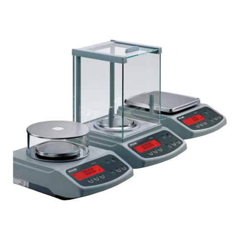
Acculab VI Series User manual

VI-
Series
VIR-
Series
Instruction Manual
for Models:
• VI-1mg • VI-200 • VI-2400
• VI-3mg • VI-350 • VI-4800
• VI-400 • VI-4kg
• VI-600 • VI-6kg
• VI-1200 • VI-10kg
®
400025.12 Rev. B

Certificate
of Calibration
We hereby certify that this instrument
was manufactured in the United States and that
it has been calibrated using appropriate reference
standards traceable to the
National Institute of Standards and
Technology.
This instrument has been fully
inspected and has passed all quality tests as speci-
fied by
Acculab quality procedures.
To assure proper measurements, it is
necessary to periodically recalibrate the instrument
using appropriate standards
as specified in the operating manual.
®
®
Phone: 800-656-4400
267-988-8702
Fax: 800-356-0338
303-940-2250
Sales Office: 67 Buck Road, Suite 131
Huntingdon Valley, PA 19006
www.acculab.com

VI/ VIR-Series Balances
Thank you for purchasing the Acculab VI / VIR-Series Electronic Balance. With proper care and treatment it will
provide years of reliable service.
Please read all operating instructions carefully and be sure to activate your warranty per the instructions listed
under the WARRANTY section of this manual.
BEFORE YOU BEGIN
• Avoid lengthy exposure to extreme heat or cold. Your balance works best when operated within the
temperature limits listed in the specifications. Always allow the unit to acclimate to a stable temperature before
calibration.
• Allow at least 30 minutes of warm up time before starting calibration to give internal components sufficient time
to stabilize.
• Keep your operating environment as clean as possible. Electrostatic fields, gravitational fields, dust, dirt,
moisture, vibration, air currents, and proximity to other electronic equipment can all have an adverse effect on
the reliability and accuracy of your unit.
• Handle with care. Carefully set weighing tray onto top of unit until level. Gently apply all items to be weighed
onto the center of tray top. Although designed to be quite durable, avoid rough treatment as this may
permanently damage the internal sensor.
TABLE OF CONTENTS
SECTION 1: VI-1mg, VI-3mg
• Operation ..................................................................................................... 4
• Calibration ..................................................................................................... 4
• Features ..................................................................................................... 5
• Keypad Functions ....................................................................................... 5
• Error Codes .................................................................................................. 6
• Accessories ............................................................................................... 6
• Specifications ............................................................................................... 7
SECTION 2: VI-200, VI-350, VI-400, VI-600, VI-1200, VI-2400, VI-4800, VI-4kg, VI-6kg, VI-10kg
• Operation ..................................................................................................... 9
• Calibration ..................................................................................................... 9
• Features ..................................................................................................... 10
• Keypad Functions ....................................................................................... 10
• Error Code ................................................................................................... 11
• Accessories ............................................................................................... 12
• Specifications ............................................................................................... 12
SECTION 3: Technical Appendices
• Memory Function ........................................................................................ 13
• RS-232 Operation (VIR Models only) .......................................................... 14
WARRANTY............................................................................................. inside back cover

Model #
VI-1mg
VI-3mg
VIR models include RS-232 interface for computer or
printer capability. Data output control in seven categories
including baud rate, manual or auto print and stability and
ambient condition presets.
Bubble level and leveling feet on all VI/VIR models.
New housing design directs
spills away from the keypad.
Brushed stainless steel weighing surfaces.
Built in lock down bracket (cable
lock sold separately).
Sealed keypad
with raised
buttons for
tactile feel
along with audio
function tone.
Large angled LCD display.
AC adapter and calibration weights
included with all models.
Housing is constructed of
sturdy ABS material with
special structural
cross-bracing
for added rigidity.
SECTION 1
For Models VI-1mg & VI-3mg
page 3

OPERATION
AC Adapter Operation:
1) Power - Use only the AC adapter provided with the unit. Use of another adapter may
damage the balance. This unit does not operate by battery power.
2) Start Up - Plug in provided adapter. Turn the unit on and allow sufficient warm up time
of at least 30 minutes.
3) Set Up - Always set up the unit on a level surface in a clean draft-free area. Place
the stainless steel spill ring base onto the raised lip on the top of the balance. Place the
stainless steel tray top on the center post and GENTLY turn until you feel the tray top
settle onto the pin stand. Place the glass draft shield on the stainless steel spill ring
base and (as needed) place the stainless steel cover on the glass draft shield. For best
results always use the draft shield assembly.
Place components listed below on the balance in the order shown.
(1) Spill Ring
(2) Weighing Tray
(3) Glass Draft Shield Cylinder
(4) Stainless Draft Shield Cover
CALIBRATION
IMPORTANT:
Please follow the calibration procedure described below. Only use the calibration weights provided or OIML
Class F1 weights. Calibration is always recommended when first using the balance or after the unit has been
moved or subjected to an extreme change in temperature. Always perform the calibration procedure AFTER the
unit has been allowed to properly warm up (at least 30 minutes). It is always recommended to recalibrate the
unit periodically during long periods of use and to always start a procedure by taring the unit to re-zero the bal-
ance.
External calibration is performed through the use of the key pad controls and proper calibration weight. Internal
factory calibration is preset and performed by accessing internal components. Access to internal components by
other than a factory authorized technician will void warranty coverage of the unit.
Calibration Procedure:
1) After allowing unit to warm for 30 minutes, remove all items from the tray top and tare the balance. The spill
ring and glass draft shield should be in place without the stainless cover.
2) After observing a stable ZERO with a stable arrow in the (g) gram mode, press and hold the CAL/MODE but-
ton until calibration weight value appears on the display.
3) Gently place the correct calibration weight as provided (or equivalent F1 Class weights) onto the tray top.
4) The + sign will disappear. Wait approximately ten seconds as the unit performs internal calibration.
IMPORTANT - Do not disturb the balance during this time. Avoid vibration and air currents.
5) When calibration is complete the unit will beep, correct calibration weight value will disappear for one second
then reappear as an active weight value. The balance is now calibrated.
6) Remove calibration weight and press the TARE button to reset the zero point. NOTE: If calibration weight
value remains on the LCD display, an improper calibration weight has been used. Remove improper weight and
repeat calibration procedure with correct weight.
Model #
VI-1mg
VI-3mg
(4)
(3)
(2)
(1)
page 4

FEATURES
• Power Up Segment Test: When first turning on the unit, all segments of the LCD
display will appear as shown. This display will remain for approximately three seconds and then reset to zero.
• Stable Reading Indication: A right-facing arrow appears on the right side of the display indicating the
weighing mode in which the unit is operating. This arrow will disappear during weighing while the unit stabilizes,
and then reappear when a stable value is reached.
• Key Tone: Pressing the ON, TARE and CAL/MODE buttons on the front panel will emit a tone indicating
registry of the function. There is no key tone with the OFF keypad.
• Overload: When an applied load exceeds the unit’s capacity, “H” will appear on the display. Remove
excessive load immediately. The unit should return to normal operation.
• Negative Value: Any tared value will be displayed as a negative number once all weight is removed from the
weighing surface. The negative sign will appear and tared value will be displayed.
• Tare: The tare feature is designed to allow the user to reset the balance to zero at any time. Tare can also be
used to eliminate the value of a pan liner, scoop, beaker, etc. from a sample or procedure, when the weighed
material needs to be held in a container and only the net weight of the material is desired. Place the container
only (without material) on the weighing tray, wait for a stable reading and then press tare. The unit returns to
zero and the weight value of the container is permanently removed from the remainder of the procedure. When
all weight is removed from the weighing tray, the tared value of the container will be displayed as a negative
number. Press the TARE key again to return the balance to zero. NOTE: The total weight of the container plus
material cannot exceed the capacity of the balance.
• Lock Down Bracket: A molded piece is attached to the back of the balance housing that can be used on an
optional basis to secure the unit. An optional cable lock can be incorporated and is sold separately as an accessory.
KEYPAD FUNCTIONS
• ON/MEMORY: Press to turn on balance. For Memory function operation refer to page 13 in Section 3.
•OFF: Press to turn off balance.
• CAL/MODE: Press and hold this key to begin calibration procedure as outlined under the CALIBRATION
section. After unit is on or calibrated, briefly pressing the same key will change the weighing mode. When
balance is turned on the unit initially defaults to the gram (g) mode. However, if the mode is changed the
balance will default to the last mode used when turned on again. The following modes may also be selected:
ounces (oz), carats (ct),and penny weight (dwt).
The right facing arrow will point to the weighing mode the unit is currently displaying. To change modes briefly
press the CAL/MODE key to scroll between grams, ounces, carats, and penny weights.
•TARE: Press tare to reset the balance to zero. Tare can be used to eliminate the weight value of a container
from a sample or procedure. The container weight is permanently removed from the remainder of the procedure.
When all weight is removed from the weighing tray, the tared value of a container will be displayed as a negative
number. Press TARE again to return the balance to zero.
▲
+
▼
8.8.8.8.8.8.
▲▲▲▲
Model #
VI-1mg
VI-3mg
page 5
ERROR CODES
Following is a description of typical error codes that may appear on VI/VIR-Series balances.
1) LThis indicates that the balance is under loaded. Check to see if the weighing
pan is properly installed and seated on the top of the unit.
2) HThis indicates that there may be an excessive weight applied to the weighing pan. It is critical
not to exceed the maximum load capacity by more than 150% or damage to the balance may
occur.
3) E-01 Capacity of LCD digit readout has been exceeded in CT and DWT modes.
4) E-02 Usually detected when the calibration operation is being attempted. It is usually the result of
the balance being exposed to vibrations, air drafts, or unstable environments. The balance
must be placed in a stable environment before calibration occurs. Before pushing the
CAL/MODE button as part of the calibration process, the LCD should display a stable ZERO
with the mode arrow stable on the gram (g) mode.
5) E-10 This will be displayed only if there is a value stored in memory and the tare button is pressed.
Memory must be cleared or the unit turned off in order to restore the normal tare function.
6) E-30 This is an indication that an electronic malfunction has occurred. The unit must be returned to
the factory for evaluation.
7) E-54 This fault will appear on the display when the unit is powered on. This occurs when the
electronics are no longer within the factory set parameters. The most common cause is from
objects being dropped onto the weighing pan or from the balance itself being dropped. The
balance must be returned to Acculab or an authorized service center for electronic evaluation
and repair.
8) ▲(in the upper left corner of display) Following are the most probable causes of this error code.
The balance must be returned to Acculab or an authorized service center for electronic
evaluation and repair.
1. There is something causing the sensor to function out of specification.
2. Rough, improper handling of the balance.
3. Liquids and other materials spilled into the balance.
NOTE: Do not attempt to access internal components or make any unauthorized repairs since this will void the
warranty.
SUPPLIED ACCESSORIES
• AC Adapter (DC 12V):
#AC-1 -For use in USA/Canada (AC 120V 60Hz) #AC-3 -For use in U.K. (AC 240V 50Hz) #AC-5 -For use in AUS/NZ (AC 240V 50Hz)
#AC-2 -For use in Europe (AC 240V 50Hz) #AC-4 -For use in Japan (AC 100V 50/60Hz)
• Calibration Weight:
#VI-1mg - One (1) 100g weight to calibrate balance at 100g OIML Class F1
#VI-3mg - Two (2) 100g weight to calibrate balance at 200g OIML Class F1
• Draft Shield & Spill Ring:
Glass Draft Shield with stainless steel cover
Stainless steel spill ring
OPTIONAL ACCESSORIES
• Cable lock, carry case
Model #
VI-1mg
VI-3mg
page 6

Acculab Model Numbers VI-1mg VI-3mg
CAPACITY 120g / 4.2328oz / 300g / 10.5821oz /
600.005ct / 77.1610dwt 750.000ct / 96.4500dwt
READABIITY (g) 1mg / 0.001g
PRECISION (g) ±2mg / 0.002g ±4mg / 0.004g
WEIGHING MODES g, oz, ct, dwt
TARE RANGE To capacity by subtraction
CALIBRATION Auto calibration from keypad w/included weight
STABILIZATION TIME (sec) 3
MAXIMUM OVERLOAD 150% of capacity
OVERLOAD INDICATION “H” reading on LCD
UNDERLOAD INDICATION “L” reading on LCD
OPERATING TEMPERATURE 50˚ - 86˚F (10˚ - 30˚C)
OPERATING HUMIDITY Less than 80% RH
DISPLAY TYPE LCD / .75” high with segment test
AUDIO TONE At startup and function keys
POWER REQUIREMENTS AC adapter only(included)
PLATFORM SIZE/TYPE 100mm diameter (4”), stainless steel
DIMENSIONS H x W x D 4.75”x5.75”x10.25” (120 x 146 x 260mm)
NET WEIGHT (lb/kg) 4/1.8
DRAFT SHIELD Glass & stainless steel w/ spill ring
SECURITY Built-in lock-down bracket, cable lock sold separately
INCLUDED ACCESSORIES Calibration weight, AC adapter
OPTIONAL ACCESSORIES Cable lock, carry case
Model #
VI-1mg
VI-3mg Specifications
Performance specifications measured within optimum temperature range after recommended warm up and proper calibration.
Specifications subject to change without notice.
page 7

Model #
• VI-200 • VI-2400
• VI-350 • VI-4800
• VI-400 • VI-4kg
• VI-600 • VI-6kg
• VI-1200 • VI-10kg
New housing design directs
spills away from the keypad.
Brushed stainless steel weighing surfaces.
Built in lock down bracket (cable
lock sold separately).
Sealed keypad
with raised
buttons for
tactile feel
along with audio
function tone.
Large angled LCD display.
9V battery operation on many models
for complete portability.
AC adapter included with all models
and calibration weights included with
all models under 1200g.
Housing is constructed of
sturdy ABS material with
special structural
cross-bracing
for added rigidity.
SECTION 2
For Models VI-200, VI-350, VI-400, VI-600, VI-1200,
VI-2400, VI-4800, VI-4kg, VI-6kg, VI-10kg
VIR models include RS-232 interface for computer or
printer capability. Data output control in seven categories
including baud rate, manual or auto print and stability and
ambient condition presets.
Bubble level and
leveling feet only
on VIR models.
page 8
VI-350
VI-2400

OPERATION
AC Adapter Operation:
CAUTION: Use only a 12V Adapter with a negative tip, as provided, to supply AC power. Use of another type of
adapter may permanently damage the unit and will void the warranty.
1) Model # VI-350 will operate on AC 120V or AC 240V, only.
2) Insert the female plug into the receptacle at the rear of the unit, and then into the desired electrical outlet.
Check you use of any extension cord which may affect power output. Unplug AC adapter when not in use for
extended periods.
Battery Operation:
1) Model #’s VI-200, VI-400, VI-600, VI-1200, VI-2400, VI-4800, VI-4kg, VI-6kg, VI-10kg operate on one 9V
Alkaline battery, or AC adapter as provided.
2) To install battery, open battery cover on bottom of balance and connect battery to snap. Place battery into its
compartment and replace the cover. Always handle battery lead wires with care. DO NOT USE EXCESSIVE
FORCE!
3) Remove battery when balance is not used for extended periods. Replace battery when LCD indicates “LO”.
CALIBRATION
**PLEASE NOTE: Calibration weights are NOT supplied with Models VI-1200, VI-2400, VI-4800, VI-4kg, VI-6kg,
or VI-10kg. All balances are factory calibrated and ready to operate. Calibration weights may be purchased
separately from your ACCULAB dealer (see Optional Accessories).
IMPORTANT: The calibration procedure is described below. Only use the calibration weights provided or OIML
Class weights. Calibration is always recommended when first using the balance or after the unit has been
moved or subjected to an extreme change in temperature. Always perform the calibration procedure AFTER the
unit has been allowed to properly warm up (at least 30 minutes). It is also recommended to recalibrate the unit
periodically during long periods of use and to always start a procedure by taring the unit to re-zero the balance.
External calibration is performed through use of the keypad controls and proper calibration weight. Internal fac-
tory calibration is preset and performed by accessing internal components. Access to internal components by
other than a factory authorized technician will void warranty coverage of this unit.
Calibration Procedure:
1) After allowing unit to warm for 30 minutes, remove all items from the tray top and tare the balance.
2) After observing a stable ZERO with a stable arrow in the (g) gram mode, press and hold the CAL/MODE but-
ton until calibration weight value appears on the display.
3) Gently place the correct calibration weight as provided (or equivalent OIML Class weights) onto the tray top.
4) The + sign will disappear. Wait approximately ten seconds as the unit performs internal calibration.
IMPORTANT - Do not disturb the balance during this time. Avoid vibration and air currents.
5) When calibration is complete the unit will beep, correct calibration weight value will disappear for one second
then reappear as an active weight value. The balance is now calibrated.
6) Remove calibration weight and press the TARE button to reset the zero point. NOTE: If calibration weight
value remains on the LCD display, an improper calibration weight has been used. Remove improper weight and
repeat calibration procedure with correct weight.
page 9
Model #
• VI-200 • VI-2400
• VI-350 • VI-4800
• VI-400 • VI-4kg
• VI-600 • VI-6kg
• VI-1200 • VI-10kg

FEATURES
• Power Up Segment Test: When first turning on the unit, all
segments of the LCD display will appear as shown. This display will remain for approximately three seconds
and then reset to zero.
• Stable Reading Indication: A right-facing arrow appears on the right side of the display indicating the
weighing mode in which the unit is operating. This arrow will disappear during weighing while the unit stabilizes,
and then reappear when a stable value is reached.
• Key Tone: Pressing the ON, TARE and CAL/MODE buttons on the front panel will emit a tone indicating
registry of the function. There is no key tone with the OFF keypad.
• Overload: When an applied load exceeds the unit’s capacity, “H” will appear on the display. Remove
excessive load immediately. The unit should return to normal operation.
• Negative Value: Any tared value will be displayed as a negative number once all weight is removed from the
weighing surface. The negative sign will appear and tared value will be displayed.
• Tare: The tare feature is designed to allow the user to reset the balance to zero at any time. Tare can also be
used to eliminate the value of a pan liner, scoop, beaker, etc. from a sample or procedure, when the weighed
material needs to be held in a container and only the net weight of the material is desired. Place the container
only (without material) on the weighing tray, wait for a stable reading and then press tare. The unit returns to
zero and the weight value of the container is permanently removed from the remainder of the procedure. When
all weight is removed from the weighing tray, the tared value of the container will be displayed as a negative
number. Press the TARE key again to return the balance to zero. NOTE: The total weight of the container plus
material cannot exceed the capacity of the balance.
• Auto Off: An auto shut off feature is provided which is operational only while the unit is operating under battery
power. The unit will automatically turn off after approximately two minutes if no active weighing takes place.
Auto shut off will not occur during operation with AC Adapter.
• Lock Down Bracket: A molded piece is attached to the back of the balance housing that can be used on an
optional basis to secure the unit. An optional cable lock can be incorporated and is sold separately as an accessory.
KEYPAD FUNCTIONS
• ON/MEMORY: Press to turn on balance. For Memory function operation refer to page 13 in Section 3.
•OFF: Press to turn off balance.
• CAL/MODE: Press and hold this key to begin calibration procedure as outlined under the CALIBRATION
section. After unit is on or calibrated, briefly pressing the same key will change the weighing mode. When
balance is turned on the unit initially defaults to the gram (g) mode. However, if the mode is changed the
balance will default to the last mode used when turned on again. The following modes may also be selected:
ounces (oz), carats (ct),and penny weight (dwt).
The right facing arrow will point to the weighing mode the unit is currently displaying. To change modes briefly
press the CAL/MODE key to scroll between grams, ounces, carats, and penny weights.
• TARE: Press tare to reset the balance to zero. Tare can be used to eliminate the weight value of a container
from a sample or procedure. The container weight is permanently removed from the remainder of the procedure.
When all weight is removed from the weighing tray, the tared value of a container will be displayed as a negative
number. Press TARE again to return the balance to zero.
page 10
▲
+
▼
8.8.8.8.8.8.
▲▲▲▲
Model #
• VI-200 • VI-2400
• VI-350 • VI-4800
• VI-400 • VI-4kg
• VI-600 • VI-6kg
• VI-1200 • VI-10kg

ERROR CODES
Following is a description of typical error codes that may appear on VI/VIR-Series bal-
ances.
1) LThis indicates that the balance is under loaded. Check to see if the weighing pan is properly
installed and seated on the top of the unit.
2) HThis indicates that there may be an excessive weight applied to the weighing pan. It is critical
not to exceed the maximum load capacity by more than 150% or damage to the balance may
occur.
3) LO This indicates low battery.
4) E-02 Usually detected when the calibration operation is being attempted. It is usually the result of
the balance being exposed to vibrations, air drafts, or unstable environments. The balance
must be placed in a stable environment before calibration occurs. Before pushing the
CAL/MODE button as part of the calibration process, the LCD should display a stable ZERO
with the mode arrow stable on the gram (g) mode.
5) E-10 This will be displayed only if there is a value stored in memory and the tare button is pressed.
Memory must be cleared or the unit turned off in order to restore the normal tare function.
6) E-30 This is an indication that an electronic malfunction has occurred. The unit must be returned to
the factory for evaluation.
7) E-54 This fault will appear on the display when the unit is powered on. This occurs when the
electronics are no longer within the factory set parameters. The most common cause is from
objects being dropped onto the weighing pan or from the balance itself being dropped. The
balance must be returned to Acculab or an authorized service center for electronic evaluation
and repair.
8) ▲(in the upper left corner of display) Following are the most probable causes of this error code.
The balance must be returned to Acculab or an authorized service center for electronic
evaluation and repair.
1. There is something causing the sensor to function out of specification.
2. Rough, improper handling of the balance.
3. Liquids and other materials spilled into the balance.
NOTE: Do not attempt to access internal components or make any unauthorized repairs since this will void the warranty.
•Parts Counting: HOW TO USE THE PARTS COUNTING FEATURE
1) To set your balance to parts counting mode, scroll through the weighing modes by pressing the CAL/MODE
keypad until a down facing arrow appears in the lower left corner on the display. The minimum parts quantity
number (5) will also be displayed as rEF 5.
2) Continue to press the CAL/MODE keypad to select the desired parts counting unit: 5, 10, 20, 50 pieces. After
“50” is displayed, the indicator will scroll back to the gram weighing mode.
3) With the selected parts counting unit still displayed, place the desired sample on the tray top. Allow the sam-
ple to stabilize for 3-5 seconds then press TARE. The parts counting function is now set for the selected 5, 10,
20, 50 piece quantity.
IMPORTANT: Minimum individual (1 piece) part weight must be greater than or equal to 2X “D” (“d” is the divi-
sion or graduation of the balance). If the sample unit weight for one piece is less than 2X “D” the display will
read “E 22”, indicating that the individual (1 piece) part weight is too low and must be increased. To reset, press
CAL/MODE and scroll through the weighing modes again to the desired parts counting value. Refer to the fol-
lowing chart for minimum unit part weight (1 piece) for your particular balance.
Balance Graduation Minimum (1 piece) Part Weight
1 gram 2 grams
0.1 gram 0.2 gram
0.01 gram 0.02 gram
Model #
• VI-200 • VI-2400
• VI-350 • VI-4800
• VI-400 • VI-4kg
• VI-600 • VI-6kg
• VI-1200 • VI-10kg
page 11

Acculab Model Numbers VI-200 VI-350 VI-400 VI-600 VI-1200 VI-2400 VI-4800 VI-4kg VI-6kg VI-10kg
CAPACITY 200g 350g 400g 600g 1200g 2400g 4800g 4000g 6000g 10000g
7.054oz 12.345oz 14.10oz 21.16oz 42.32oz 84.65oz 169.31oz 141.0oz 211.6oz 352.7oz
126.602dwt 225.055dwt 257.20dwt 385.80dwt 771.61dwt 1543.23dwt 3086.47dwt 2572.0dwt 3858.0dwt 6430.1dwt
6.430ozt 11.252ozt 12.86ozt 19.29ozt 38.58ozt 77.16ozt 154.32ozt 128.6ozt 192.9ozt 321.5ozt
READABIITY (g) 0.01 0.1 1
PRECISION (g) ±0.01 ±0.1 ±1
WEIGHING MODES g, oz, dwt, ozt & parts counting
TARE RANGE To capacity by subtraction
CALIBRATION Auto calibration from keypad w/included weight Auto calibration from keypad
STABILIZATION 3 seconds
MAXIMUM OVERLOAD 150% of capacity
OVERLOAD INDICATION “H” reading on LCD
UNDERLOAD INDICATION “L” reading on LCD
OPERATING TEMPERATURE 50˚ - 86˚F (10˚ - 30˚C)
OPERATING HUMIDITY Less than 80% RH
DISPLAY TYPE LCD / .75” high with segment test
AUDIO TONE At startup and function keys
POWER REQUIREMENTS 9V alkaline battery AC adapter 9V alkaline battery or AC adapter
or AC adapter only
PLATFORM SIZE/TYPE 4.5” diameter (115mm), 5.5”x5.7” (141 x 145mm), stainless steel
stainless steel
DIMENSIONS H x W x D 3.5”x5.75”x10.25” (89 x 146 x 260mm)
NET WEIGHT (lb/kg) 4/1.8
SECURITY Built-in lock-down bracket, cable lock sold separately
INCLUDED ACCESSORIES Calibration weight & AC adapter AC adapter only
OPTIONAL ACCESSORIES Cable lock, carry case Cable lock, calibration weight, carry case
SUPPLIED ACCESSORIES
• Calibration Weight with the following models:
VI-200 - One (1) 200g weight to calibrate balance at 200g OIML Class M1
VI-350 - One (1) 200g weight to calibrate balance at 200g OIML Class M1
VI-400 - One (1) 200g weight to calibrate balance at 200g OIML Class M2
VI-600 - Two (2) 200g weights to calibrate balance at 400g OIML Class M2
• AC Adapter (DC12V)
#AC-1 -For use in USA/Canada (AC 120V 60Hz)
#AC-2 -For use in Europe (AC 240V 50Hz)
#AC-3 -For use in U.K. (AC 240V 50Hz)
#AC-4 -For use in Japan (AC 100V 50/60Hz)
#AC-5 -For use in AUS/NZ (AC 240V 50Hz)
OPTIONAL
ACCESSORIES
• Cable Lock, Carry Case
• Calibration Weight
VI-1200 - One (1) 1kg weight to calibrate balance at 1000g OIML Class M2
VI-2400 - One (1) 2kg weight to calibrate balance at 2000g OIML Class M2
VI-4800 - Two (2) 2kg weights to calibrate balance at 4000g OIML Class M2
VI-4kg - One (1) 2kg weight to calibrate balance at 2000g OIML Class M2
VI-6kg - Two (2) 2kg weights to calibrate balance at 4000g OIML Class M2
VI-10kg - Three(3) 2kg weights to calibrate balance at 6000g OIML Class M2
Specifications
Performance specifications measured within optimum temperature range after recommended warm up and proper calibration.
Specifications subject to change without notice.
Model #
• VI-200 • VI-2400
• VI-350 • VI-4800
• VI-400 • VI-4kg
• VI-600 • VI-6kg
• VI-1200 • VI-10kg
page 12

TECHNICAL
APPENDICES SECTION 3
page 13
The Memory Key & Function
All VI/VIR-Series balances include a unique memory function that allows cumulative weighing up to the capacity
of the balance. Using the memory function requires the following steps:
1. After making sure that the balance is on, start by pressing the “TARE/PRINT” key to tare the balance out to
zero.
2. Place a sample on the stainless steel tray-top, and when the displayed weight is stable, briefly press the
“ON/MEMORY” key. This action adds the displayed weight value to the value contained in memory buffer,
which is initially set to zero, and re-tares the balance so the LCD once again reads “0” (zero).
3. Repeat #2, above, as many times as you want until you are ready to see the cumulative weight of all samples
weighed.
4. To view the cumulative weight, press and hold the “ON/MEMORY” key until a beep is heard. When the beep
sounds, the memory buffer is dumped to the LCD and the total sum of everything weighed is visible. This also
clears out the memory buffer and re-initializes it to zero.
5. Briefly press “TARE/PRINT” key in order to tare out the balance, and you are ready to proceed with normal
balance operation.
A few things to keep in mind:
- If you begin using the memory function, and decide that you do not need to do cumulative weighing at the
moment, perform #4 & 5 above to jump out of the memory function mode.
- You cannot switch weighing modes after beginning to use the memory function. If you want to do cumulative
weighing using a different weighing mode, like pennyweight (dwt), switch to that weighing mode first, before
invoking the memory function.
- If your balance is a VIR-Series equipped with RS-232, and you are properly connected to a printer or comput-
er, any displayed weight values can be printed at any point during use of the memory function by simply press-
ing and holding the “TARE/PRINT” key until a beep is heard.

VIR-Series RS-232 Bi-Directional Serial Communications
All VIR-Series balances are equipped with a standard 9-pin male, bi-directional RS-232 interface located at the rear of the
balance. The RS-232 communication parameters are configurable with respect to baud rate, parity, # of stop bits, and hand-
shake. A seven-bit ASCII data stream is sent from the balance to an appropriate connected computer or printer via the prop-
er data interface cable. Correctly configured cables can be purchased from Acculab, or, can be made by the user. See the
table “Data Interface Cable PIN Configuration For VIR-Series Balances”.
User Configurable Balance Parameters
The table "User Configurable Internal Menu Codes" shows the balance parameters that are user configurable. Changing
configurable internal balance parameters requires accessing the balance internal menu system via the keypad. Navigating
the menu system is performed as follows:
1. To gain access to the balance internal menu system, start with the balance turned off. Briefly press the "ON/MEMORY"
key and immediately (and briefly) press the "TARE/PRINT" key while all LCD segments are illuminated. You should see a
"1" toward the left side of the LCD. This is the "left" segment value.
2. To increment the displayed digit within any segment, briefly press the "TARE/PRINT" key repeatedly until you reach your
target value.
3. To switch from one code segment to another, IE. from the left to center digit, center to right digit, or right to left digit, briefly
press the "CAL/MODE" key. Increment each digit segment by the method explained in #2, above.
4. When switching from the center to right segment, the number displayed is the setting that is currently selected - marked by
a small right facing arrow that points to the “g” indicator on the lower right side of the display.
5. To select a new value, increment the third segment (#2) until you reach the new desired value. To lock in this new value,
press and hold the "CAL/MODE" key until the small right facing arrow appears and points to the “g” indicator on the
lower right side of the display.
6. If you need to move on and change other internal values, do so by repeating steps 2-5 above.
7. To finalize and save all revised parameter settings, press and hold the "TARE/PRINT" key until the balance resets. All your
new settings are now balance defaults at startup.
Note: To reset the balance to all its factory default parameters, specify the menu code "9 - 1" and invoke step #7, above.
Printing To A Printer Or Computer
Printing with VIR-Series balances simply means that the displayed LCD contents are sent out the 9-pin RS-232 port to either
a connected printer or computer. To successfully print the following conditions must exist:
1. Attach the balance to a printer or computer using the appropriate data interface cable. The correct cable must be used to
connect the two devices together. Correctly configured cables can be purchased from Acculab, or, can be made by the
user. See the table “Data Interface Cable PIN Configuration For VIR-Series Balances”.
2. The RS-232 settings on both the balance and printer (or computer) must be the same. Both devices must be set to the
same number of data bits (“7”, not configurable), baud rate, parity, stop bits and handshake.
3. If the balance is set to manual print (default), press and hold the “TARE/PRINT” key until an audible beep is heard. The
LCD contents will be sent out the RS-232 port to the attached device.
page 14
TECHNICAL
APPENDICES

Verifying A Correct Cable Connection
This procedure assumes the following:
- You are using a PC that is running either Windows 95/98/NT4.0.
- The PC has Hyperterminal installed, (a communications package that ships with Windows).
- The interface cable is properly attached to both the balance RS-232 port and PC port (COMx).
- The balance communication parameters are all set to their defaults of 1200 baud, odd parity, and 1 stop bit.
Perform the following steps:
1. Turn on your balance, and invoke Hyperterminal.
2. Click “File-->Properties” to bring up the Properties window.
3. Make sure the box called “Connect Using” says “Direct to Comx”.
... “x” is the COM port of your PC, usually, either 1 or 2.
4. Click the “Configure” button, and check that the following values are selected:
Bits per second: 1200
Data bits: 7
Parity: Odd
Stop bits: 1
Flow control: Hardware
5. Exit back to the main Hyperterminal screen, by clicking “OK” twice. The bottom-left of your window should say
“Connected”. At this point, press and hold the “TARE/PRINT” button on the balance. The value on the LCD should show up in
the Hyperterminal window.
Controlling The Balance Remotely Via Computer
Because the VIR-Series RS-232 interface is bi-directional, a connected computer can remotely control the balance. There are
nine (9) balance functions, as listed in the table entitled “Remote Balance Operation Functions & Control Codes” (page 17)
that can be remotely invoked from an attached computer. The process of sending these codes varies depending on the com-
puter software used. Programming languages such as C++ and Visual Basic can be used to create routines to grab data
from the balance. There are also many software packages commercially available to help users capture data from RS-232-
enabled laboratory devices, like the VIR-Series.
page 15
TECHNICAL
APPENDICES

User Configurable Internal Menu Codes
Segment Position
Category L C R Value
Ambient Conditions 1 1 1 very stable
1 1 2* stable (default)
1 1 3 unstable
1 1 4 very unstable
Stability Range 1 3 1 ⁄digit
132fidigit
1 3 3 1 digit
1 3 4* 2 digits
1 3 5 4 digits
External CAL Units 1 4 1* grams (default)
External Calibration 1 5 1* external calibration is enabled (default)
1 5 2 external calibration is disabled
Auto Zero 1 6 1* on (default)
162off
Baud Rate 5 1 1 150
5 1 2 300
5 1 3 600
5 1 4* 1200 (default)
5 1 5 2400
5 1 6 4800
5 1 7 9600
Parity 5 2 1 mark
5 2 2 space
5 2 3* odd (default)
5 2 4 even
Stop Bits 5 3 1* 1 stop bit (default)
5 3 2 2 stop bits
Handshake 5 4 1 software
5 4 2 hardware, w/2 chars after CTS (default)
5 4 3* hardware, w/1 char after CTS
Print Stream 6 1 1 manual print, regardless of stability
6 1 2* manual print when stable (default)
6 1 3 continuous print, regardless of stability
6 1 4 continuous print, when stable
Printed Output 7 1 1* LCD contents only (default)
7 1 2 header and LCD contents
Menu Codes Reset 9 1 1 reset balance to factory defaults
Note: Settings 5--, 6-- and 7-- have no effect on VI-Series balances because they affect
performance of the RS-232 port included with VIR-Series balances only.
*=Factory default setting.
page 16
TECHNICAL
APPENDICES

Remote Balance Operation Functions & Control Codes
PC Key
Remote Function How Balance is Affected Control Codes
Very Stable Conditions Changes balance state ESC K
Stable Conditions Changes balance state ESC L
Unstable Conditions Changes balance state ESC M
Very Unstable Conditions Changes balance state ESC N
Disable Balance Keypad Changes balance state ESC O
Enable Balance Keypad Changes balance state ESC R
Print When Stable Performs a function ESC P
Tare Performs a function ESC T
Invoke External Calibration Performs a function ESC W
Data Interface Cable PIN Configuration For VIR-Series Balances
RxD 2
TxD 3
Signal Ground 5
Acculab VIR-Series
Balance 9-PIN port
Standard RS-232
9-PIN Connector
3 TxD
2 RxD
5 Signal Ground
RxD 2
TxD 3
Signal Ground 5
Acculab VIR-Series
Balance 9-PIN port
Standard RS-232
25-PIN Connector
2 TxD
3 RxD
7 Signal Ground
page 17
TECHNICAL
APPENDICES

Warranty
Two Year Limited Warranty
(effective February 1, 2002)
Duration: The Acculab balances and scales are warranted as a consumer product
to the original consumer purchaser for a period of two (2) years from the original
purchase date.
Coverage: The Acculab balances and scales are warranted against defects in
material and workmanship. The warranty includes parts, labor and return ship-
ping to customer (ground freight).
This warranty does not cover batteries and shall not apply to any product dam-
aged due to accident, misuse, abuse, lightning strike, power surges, improper
service, improper packaging or other causes not arising out of defects in material
or workmanship.
Disclaimer: The original purchaser’s sole remedy, Acculab and its Authorized
Distributors sole liability are set forth herein. In no event shall Acculab or its
Authorized Distributors be liable for any damages, incidental or consequential,
expenses, lost profits, lost savings, or any other claims due to the use or inability
to use the product/s. Acculab shall limit its obligations under warranty to a time
not to exceed the original product warranty period set forth herein. Acculab
reserves the right to either repair or replace the balance or scale. This warranty
gives you specific legal rights and you may have other rights which may be dif-
ferent from state to state.
In the event that service is required, the Customer/Distributor should call Acculab
(800-656-4400 or 267-988-8702) for technical support and proper return autho-
rization if needed. The product must be delivered to Acculab Service Center with-
in the warranty period, freight charges prepaid. The customer is responsible for
product removal, installation and proper packing in order to prevent damage
while shipping to Acculab Service Center.
This limited manufacturer warranty supersedes all other warranties pertaining to
the Acculab products, whether expressed or implied. Claims may be made by
calling toll free 1-800-656-4400, local 267-988-8702, by fax toll free 1-800-
356-0338, local fax 303-940-2250 or in writing to:
Acculab
67 Buck Road, Suite 131
Huntingdon Valley, PA 19006
Acculab Service Center
6542 Fig Street
Arvada, CO 80004

Specifications subject to change without notice.
as applicable
®
Phone: 800-656-4400
267-988-8702
Fax: 800-356-0338
303-940-2250
Sales Office: 67 Buck Road, Suite 131
Huntingdon Valley, PA 19006
www.acculab.com
400025.1 Rev. B
This manual suits for next models
13
Table of contents
Other Acculab Scale manuals

Acculab
Acculab SVI-50C User manual

Acculab
Acculab 98648-013-61 User manual

Acculab
Acculab ATL-224 User manual

Acculab
Acculab SV-30 User manual

Acculab
Acculab PP-62 User manual

Acculab
Acculab VICON User manual

Acculab
Acculab GSI-200 User manual

Acculab
Acculab ECL6 User manual

Acculab
Acculab POCKET PRO PP-250B User manual

Acculab
Acculab PP-62 User manual