Sine Wave
Data
Quartz
Oscillator
D/A
Converter
Output
Frequency
Divider
0110
Demodulated output
Phase Detector
FM Wave Signal
Input
Imaginary
Part
Real
Part
Division
Differentiation
tanθ
(tan1)
Phase
Angle(θ)
Arctangent
f0
Noise or adjacent
broadcast station
Narrow IF bandwidth
reduces interference
Wide IF bandwidth
is susceptible to
degradation by
noise and interference
DDS Local Oscillator
Attenuator
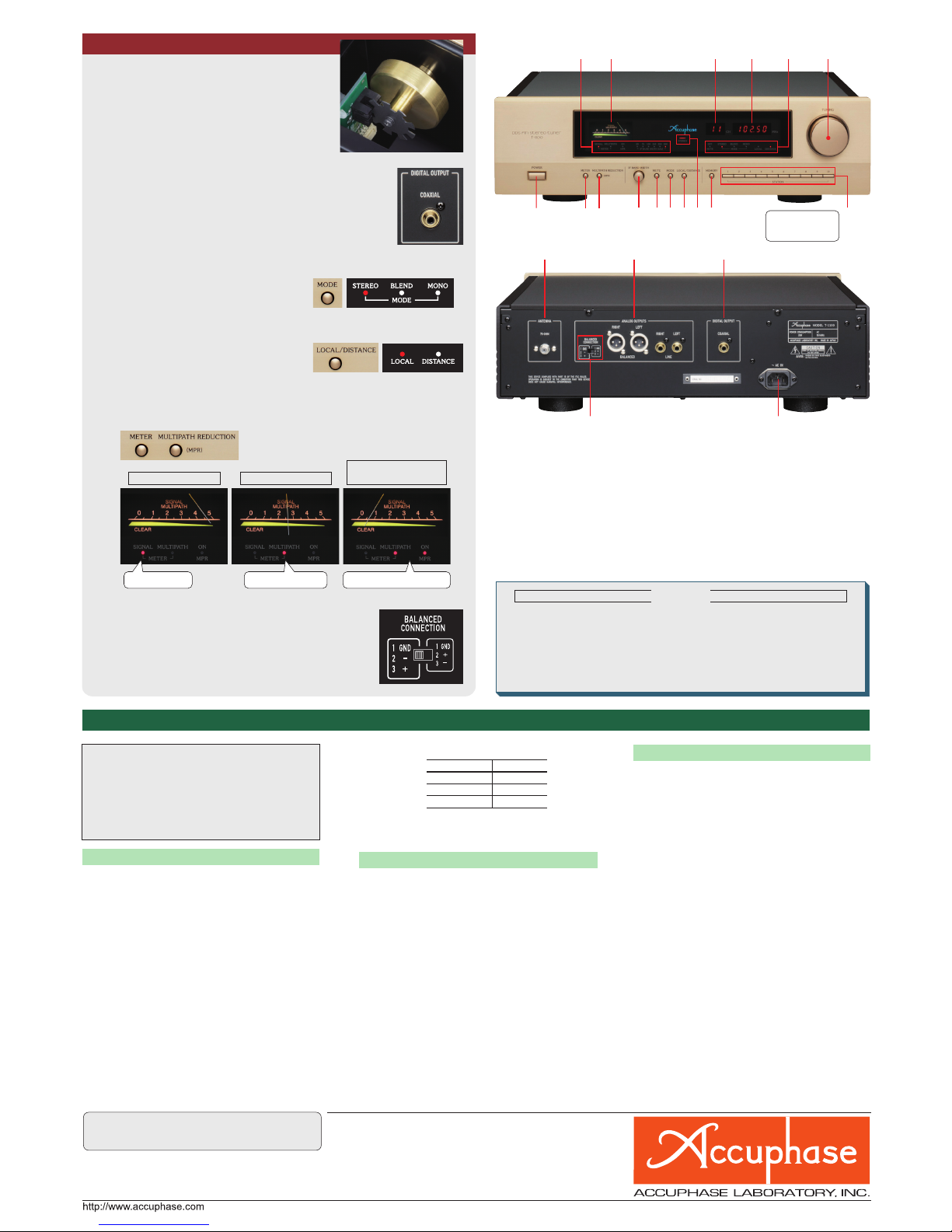
Local/Distance
Selector
Double
Balanced
Mixer
Double
Balanced
Mixer IF output
FM Antenna
Double-Tuned Circuit
RF
Amplifier Double-Tuned Circuit
AGC
Direct
Wave
Transmitter
Reflected
Wave
■Front End Circuit Diagram
■DDS Block Diagram
■Digital FM Demodulator
Coils used in double-tuned circuits
■IF bandwidth switchable in 6 stages
■FM Propagation Characteristics
The range of available program sources is getting
ever more varied: Compact Discs, analog records,
and net based music distribution, to name but a
few. But the FM tuner still has a special role to
play, since broadcasts cover the entire spectrum
from live performances of time-honored classical
works to the latest hits. The FM band provides a
rich choice of music all day long. In addition,
many local stations have recently come onto
stage using the live broadcast medium to best
advantage.
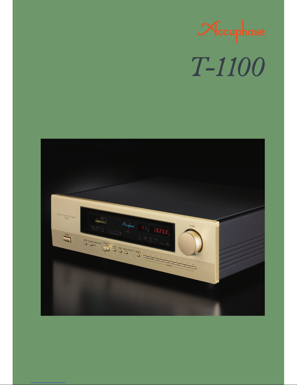
The T-1100 is a successor model to the highly
praised T-1000. Thanks to a blend of latest RF
circuit design with sophisticated digital signal
processing implemented by a high-speed, high-
precision DSP chip, it has become possible to
move most major functions of the tuner into the
digital domain without sacrificing performance or
sound quality. Audiophiles and music lovers can
now enjoy FM stereo at its best.
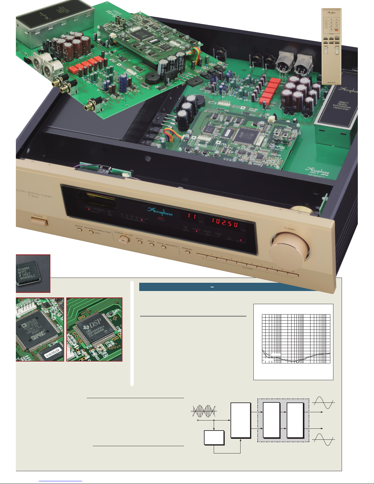
The newly developed front end features a double-
tuned circuit that optimizes sensitivity and
selectivity, as well as the revolutionary DDS
(Direct Digital Synthesis) principle for the local
oscillator. All functions after the intermediate
frequency (IF) stage are implemented using digital
signal processing in completely new and
innovative ways. This comprises the variable
bandwidth IF filter, multipath reduction function,
digital FM detector and DS-DC stereo
demodulator. The result is an FM tuner unlike any
other, offering further enhanced performance and
sound quality. Other attractive features include a
20-station memory, a coaxial output for digital
signal connection, two sets of line and balanced
analog outputs, and a supplied Remote
Commander for operation convenience. In sum,
this is a lavishly designed FM tuner that will meet
and surpass even the highest expectations.
The FM demodulator circuit is a crucial component that has a
significant effect on distortion and noise characteristics of the tuner’s
audio output. In the T-1100, the imaginary part of the digitized FM
signal is divided by the real part to extract the tangent of the phase
angle (
θ) . By calculating the arctangent from this, the phase angle
can be determined. Differentiation is then used to obtain the time
variation resulting in the FM demodulated output (audio output).
Ideal Digital FM Demodulation Principle
Variable Bandwidth IF Filter Improves Interference Performance
Multipath Reduction Function (MPR) Minimizes Reflections
DDS(Direct Digital Synthesis)
The signal from the antenna input is routed to an RF amplifier
and then mixed with the signal from a local oscillator for
conversion into the intermediate frequency (IF). The local
oscillator here is a highly advanced DDS (Direct Digital
Synthesis) circuit.
●The output of a quartz oscillator is supplied to the frequency
divider to create the timing (namely the sampling frequency)
with which the sine wave data are read out.
●Using this sampling frequency, the sine wave data are read
in the D/A converter to create the analog waveform output.
●Because there is no feedback loop, the frequency purity of
the D/A converter output can be kept identical to that of the
quartz oscillator.
■Anattenuatorintheinputstageenablesthetunertooperateatitsoptimum
pointalsowheninputlevelsareextremelyhigh,suchasinthevicinityofa
broadcasttowerorwhenusingacablenetwork.
■Two-stagedouble-tunedfrontendeliminatesintermodulationdistortionwith
strongsignals.
■Dual-gateMOS-FETsintheRFamplifierstageensureexcellentthird-order
intermodulationcharacteristics.
■Two-stage double-balanced mixer suppresses undesired signal compo-
nents.
■RevolutionaryDDSlocaloscillatorachievesamazingS/Nratio.
The IF BANDWIDTH selector of the T-1100 provides a choice of six settings
(50, 75, 100, 150, 250, 500 kHz). Normally, a wider bandwidth setting is pref-
erable in terms of perform-
ance characteristics, but
by restricting the band-
width, noise can be re-
duced in certain situations,
making it easier to obtain
a good quality signal from
a station affected by inter-
ference from a strong ad-
jacent station.
The variable bandwidth IF
filter is implemented using
a FIR (Finite Impulse Re-
sponse) type digital filter
with perfectly linear phase
characteristics, thereby
eliminating the phase shift
that can occur with con-
ventional IF bandwidth fil-
ters.
Double-Tuned Front End Eliminates Problems With High Input Signal Levels
4HE ULTIMATE &- STEREO TUNER ,ATEST 2& TECHNOLOGY AND ADVANCED
DIGITAL PROCESSING TECHNIQUES COME TOGETHER ON THE HIGHEST PLANE !LL
FUNCTIONS AFTER THE INTERMEDIATE FREQUENCY )& STAGE ARE PERFORMED BY
$30 SOFTWARE INCLUDING THE VARIABLE BANDWIDTH )& FILTER MULTIPATH
REDUCTION -02 FUNCTION DIGITAL &- DETECTOR AND $3$# STEREO
DEMODULATOR0ULSETUNINGPRINCIPLEALLOWSMANUALTUNINGANDSTATION
MEMORYTUNING$IGITALOUTPUTINCREASESCONNECTIONOPTIONS
Multipath reception refers to a condition where the same broadcast signal
reaches the antenna via several different propagation routes. In the case of
FM, this occurs when the signal travels to the antenna in a straight line, but
is also reflected and therefore slightly delayed by buildings, mountains or
other tall obstructions.
When the direct waves and
reflected waves are re-
ceived together, distortion
and noise occur.
The high-speed, high-
precision DSP chip in the
T-1100 makes it possible
to perform multipath reduc-
tion (MPR) through signal
processing that effectively
suppresses the harmful re-
flected components. This
technique which is based
on adaptive filtering princi-
ples ensures that only the
desirable direct wave com-
ponents are received, re-
sulting in high-quality audio
output.
■IF bandwidth is selected by turning knob
(with LED indication)