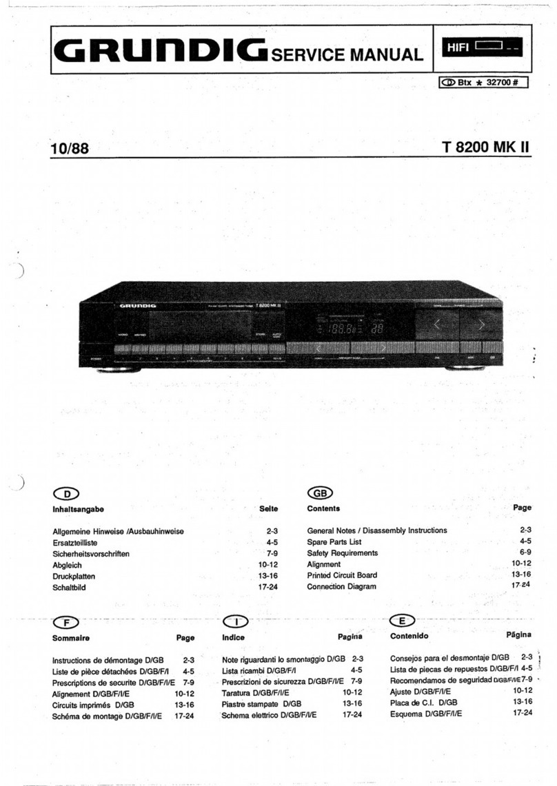
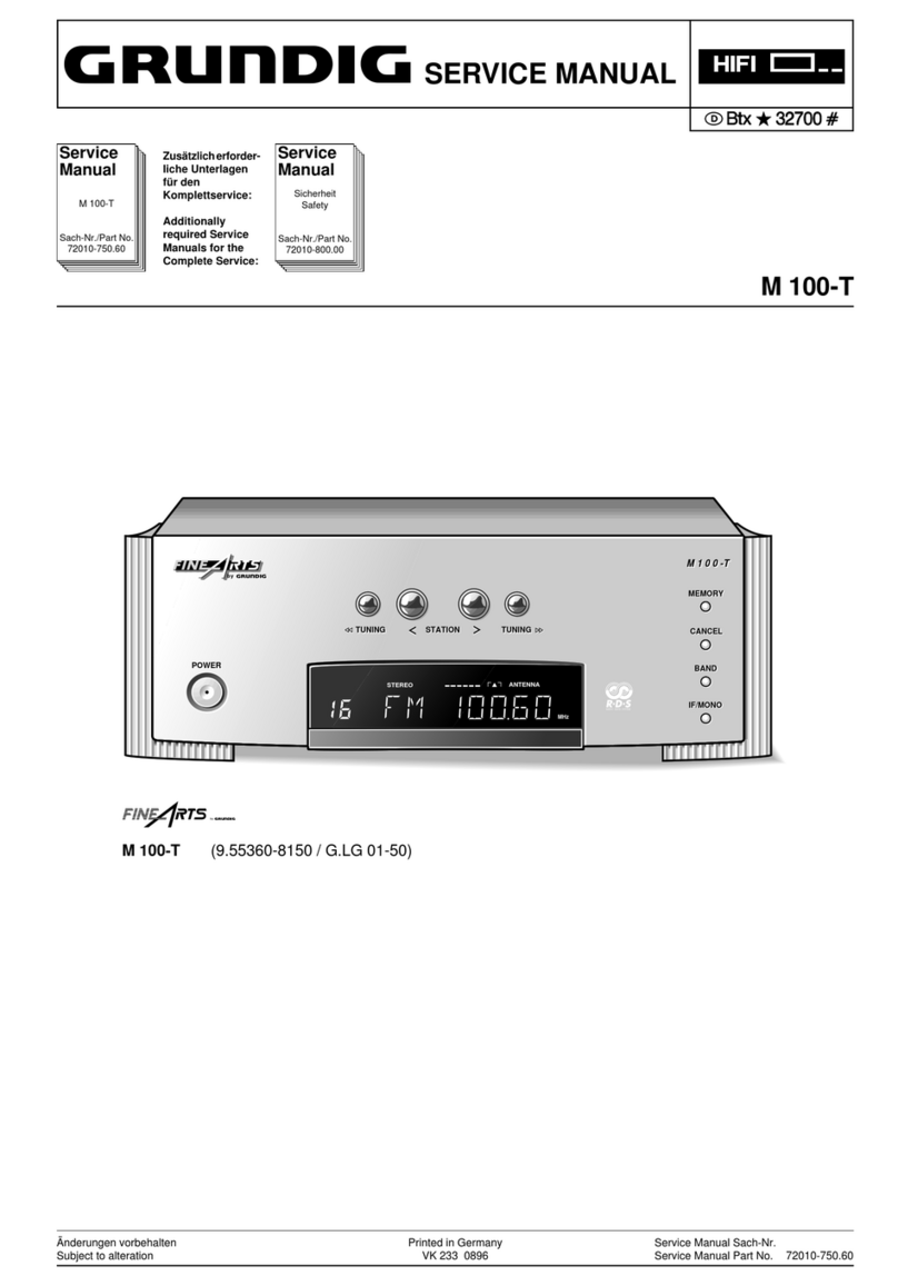
Grundig T 7500 User manual

perating
instructions
|
Mode
d’emploi
~
Istruzioni
per
|'uso
Gebruiksaanwijzing
Instrucciones
de
manejo

Wire
bridge
horizontal
=
AM
and
FM
(300
©
and
75
Q)
aerials
connected.
Wire
bridge
vertical
=
aerials
separated.
Boucle
en
position
horizontale
=
antennes
AM
et
FM
(300
2
et
75
Q)
internément
liées.
Boucle
en
position
verticale
=
antennes
AM
et
FM
séparées.
.
:
Me
Ponticello
in
posizione
orizzontale
=
antenne
AM
e
FM
(300
0
e
75
Q)
collegate
internamente.
Ponticello
in
posizione
verticale
=
antenne
AM
e
FM
separate.
Draadbrug
horizontaal
=
antennes
voor
AM
en
FM
(300
©
en
75
©)
doorverbonden.
Draadbrug
verticaal
=
antennes
gescheiden.
Puente
de
alambre
horizontal
=
antenas
para
AM
y
FM
(300
0
y
75
Q)
unidas.
Puente
de
alambre
vertical
=
antenas
separadas.

SoaUMtiGaneMTES
EARS

This
tuner
contains
a
microcomputer
which
controls
not
only
all
the
tuning
operations
of
the
high-precision
synthesiser,
but
also
-quickly
and
effectively
processes
the
data
|
for
up
to
15
preset
VHF,
MW
or
LW
stations.
Among
the
extra
operating
facilities
of
the
T
7500
are:
-
@
Manual
tuning
either
in
discrete
steps
or
in
large
steps
for
high
speed.
@
Automatic
station
location
(self-seek)
in
both
directions
with
an
automatic
check
on
the
reception
quality
of
each
station
located.
@
A
memory
which
can
be
programmed
for
up
to
15
stations
(VHF,
MW
or
LW).
@
Memory
facility
for
station
abbreviations
containing
up
to
4
letters
and/or
figures
which
appears
immediately
whenever
the
corresponding
station
is
selected
(alphanumeric
station
identification).
@
GRUNDIG
TUNOSCOPE®
as
an
aid
to
precise
tuning
of
stations.
@
Pre-programming
of
mono
or
stereo
reception
in
the
case
of
VHF
stations.
@
High
dynamic
selectivity
for
VHF
stations,
even
if
the
signal
strength
is
high.
@
Switchable
muting
on
all
wavebands.
@
Memory
scan
for
rapidly
reviewing
and
selecting
the
preset
stations.
®
Registered
trade-mark
@
FREE
button
for
indicating
unallocated
preset
station
numbers.
@
Compare
function
for
preventing
alloca-
tion
of
more
than
one
station
number
to
the
same
station.
When
a
station
is
located
by
.
the
automatic
location
system,
the
result
of
comparing
the
memory
contents
is
automati-
cally
shown
immediately
after
the
check
phase.
@
Non-volatile
memory
which
does
not
require
a
battery.
The
data
in
the
memory
is
retained
even
if
there
is
a
mains
failure.
Sha
NET
ASCe
Nr
oe
DNS
wens
ort

ar
NAPA
I
ECR
NER
MTT
TT
RO
et
NETS
ML
oN
A
CEA
IERIE
FE
ACES
FO
Re
Ee
eT
ein
ee
ere
ee
eee
‘Controls
and
Sockets
|
The
controls
of
the
T
7500
are
so
designed
that
buttons
used
frequently
have
a
bright
finish,
while
subsidiary
function
buttons
are
coloured
an
unobtrusive
black.
@
Mains
(POWER)
Switch
—
Button
pressed
in
=
tuneron
Button
released
=
tuner
off
©
Selected
Waveband
Display
FM
=
VHF
MW
=
medium
wave
LW.
=
long
wave
©
Display
For
indicating
the
frequency
tuned
to
or
the
station
abbreviation,
and
various
information
on
the
station
numbers,
viz.
NEW,
FREE
(=
not
allocated),
FULL.
@
Display
showing
the
function
being
performed
or
the
station
number.
HA
=
manual
tuning
AS
=
automatic
station
location
CH
=
station
check
after
automatic
location
ee
Oe
ee)
ee
8
ge
ee
ee
am
ee
©
Illuminated
Display
indicating:
STORE
=
Memory
ready
to
receive
data
|
FM
STEREO
=
Stereo
reception
FM
MONO
=
Mono
reception
MUTING
=
Muting
©
Tuning
Meter
Indicates
signal-strength
(AM)
or
fieldstrength
(VHF).
@
TUNOSCOPE
The
central
green
light
comes
on
when
tuning
is
precise.
©
L.S.M.
(Last
Station
Memory)
Indicator
This
must
light
up
before
the
tuner
is
switched
off
if
the
same
station
is
to
come
back
on
automatically
when
the
set
is
switched
on
again.
©
STORE
Button
Press
to
enter
station
information
in
memory
before
allocating
a
number
to
the
station.
@
Station
Selection
Buttons
For
selecting
the
pre-set
stations
1
-
15.
@
Waveband
Seiection
Buttons
FM
=
VHF
—
MW
=
medium
wave
LW
=
long
wave
@®
Manual
Tuning
Buttons
Press
DOWN
button
to
reduce
fre-
quency,
press
UP
button
to
increase
frequency.
In
each
case
the
rate
of
tuning
can
be
increased
by
pressing
the
centre
button
(FAST)
as
well.
@®
Start
Buttons
for
Automatic
Station
Location
(AUTO-SEARCH):
Press
¢
to
decrease
frequency,
press
>
to
increase
frequency.
(With
control
for
adjusting
station
location
threshold
in
middle).
@
MEMORY-SCAN
Buttons
To
review
the
allocated
station
numbers
in
sequence
press
one
of
these
buttons:
4
=
review
in
decreasing
sequence
>
=
review
in
increasing
sequence.
@
FREE
Button
Checks
through
pre-set
stations
and
shows
any
unallocated
numbers
in
the
display
@.
Can
also
be
used
to
erase
data from
memory
when
pressed
after
pressing
the
STORE
button.
@
COMP.
Button
Compares
any
frequency
tuned
to
with
those
of
stations
already
in
the
memory,
and
if it
has
already
been
entered,
indicates
the
station
number
allocated.
If
it
is
not
yet
stored
in
the
memory,
the
word
NEW
will
appear
in
the
display.
®
MONO
Button
For
switching
over
to
mono
reception
on
VHF,
eg:
if
stereo
broadcasts
are
subject
to
interference.

@®
MUTING
Button
For
muting
the
sound
between
stations
when
tuning.
@
A-2Z/0-9
Button
Press
to
enter
a
station
abbreviation
with
the
tuning
buttons
@.
@
SHIFT
Button
Moves
the
station
abbreviation
symbols
entered
in
the
display
@
one
place
to
the
left.
@
FREQ./NAME
Button
.
Switches
the
station
display
from
station
abbreviation
to
frequency
and
vice
versa.
—
-®
Sockets
for
AM
aerial
(LW
and
MW)Y
,
|
earth
<
and 300
2
VHF
dipoles"I=
®
Coaxial
socket
for
75
0
aerial.
@
Level
Control
For
adjusting
output
voltages
at
sockets
@
and
@).
@
DIN
Output
Socket
For
(pre)amplifier
@
Phono
Sockets
For
(pre)amplifier.
Positioning
If
hifi
units
are
placed
above
each
other
in
racks,
in
cabinets
or
in
table-top
racks,
the
amplifier
or
preamplifier
should
always
be
at
the
top.
In
the
GRUNDIG
hifi
range
you
will
find
suitable
racks
and
Compact
Systems
for
your
GRUNDIG
hifi
units.
Your
dealer
wiil
be
pleased
to
advise
you.
Important:
Do
not
site
mains
cables
near
audio
input
leads
such
as
those
from
the
record
deck,
cassette
deck,
tuner
or
loudspeakers.
Mains
Connection
The
tuner
is
designed
to
operate
only
from
AC
mains
(50/60
Hz).
The
mains
voltage
to
which
it
is
adjusted
in
the
factory
is
specified
on
the
back
of
the
set.
Changes
to
other
voltages
should
only
be
carried
out
by
the
dealer
in
accordance
with
the
data
given
in
the
set.
Additional
Information
for
Sets
Used
in
Great
Britain
We
recommend
that
a
13
amp
3-pin
plug
fitted
with
a
3
amp
fuse
be
used.
The
brown
lead
must
be
connected
to
the
live
pin
(marked
“L”
or
“red”
or
“brown”)
and
the
blue
to
the
neutral
pin
(marked
“N”
or
“black”
or
“blue”).
On
no
account
should
either
wire
be
connected
to
the
earth
pin
(marked
“E”
or
“green/yellow”).
If
other
mains
plugs
are
used,
ensure
that
they
are
protected
with
a
3
amp
fuse.
Sets
sold
in
Great
Britain
are
suitable
for
operation
from
a
mains
supply
of
240
V
AC.

Connection
to
an
Amplifier
There
is
a
choice
of
two
outputs
for
connec-
ting
to
an
amplifier:
@
The
DIN
socket
@
with
adjustable
output
voltage.
To
match
the
tuner
to
amplifiers
made
by
other
manufacturers,
the
output
voltage
can
be
varied
between
175
and
1500
mV
with
40
kHz
deviation
and
1000
Hz
modulation
using
the
level
control
@).
With
this
contro!
in
its
centre
lock-in
position
the
output
voltage
is
800
mV.
A
—
suitable
connecting
cable
is
supplied
with
the
tuner
(GRUNDIG
cable
379a).
_
-@
The
two
phono
sockets
@).
These
are
in
-
parallel
with
the
DIN
socket
@
and
the
output
level
can
therefore
also
be
adjusted
with
control
@).
A
control
voltage
is
available
at
the
DIN
output
socket
which
allows
suitably
designed
(pre)amplifiers
to
be
switched
on
and
off
together
with
the
tuner.
Example
of
a
suitable
unit
the
GRUNDIG
is
XV
7500.
The
GRUNDIG
cable
392
(included
with
the
amplifiers),
which
has
the
necessary
control
lead
in
it,
may
be
used
for
connection.
lf
required,
the
output
sockets
can
be
used
for
recording
on
tape.
The
DIN
socket
@
provides
an
output
of
0.87
mV/kQ
(for
40
kHz
deviation
and
1
kHz
modulation
frequency).
The
phono
socket
@
may
be
used
as
a
voltage
source
for
high-level
recordings
|
(800
mV
with
the
level
control
@
in
the
central
lock-in
position).
_
Aerials
In
good
reception
areas
or
in
the
neighbour-
hood
of
transmitters
it
is
possible
to
obtain
good
reception
with
a
simple
room
dipole,
eg:
the
GRUNDIG
VHF
indoor
aerial.
However,
to
obtain
optimum
reception
quality
itis
essential
to
install
a
good
outdoor
VHF
dipole
aerial.
This
is
especially
true
of
stereo
broadcasts,
which
require
an
aerial
voltage
about
ten
times
higher
than
for
mono
reception.
Makeshift
aerials
will
no
longer
be
satisfactory
in
this
case
and
will
be
no
more
than
an
expediency,
especially
in
unfavoura-
ble
reception
areas,
eg:
in
mountainous
regions
or
in
areas
distant
from
the
VHF
transmitter.
The
outdoor
dipole
should
be
mounted
as
high
as
possible
and
should
be
free-standing
on
the
roof.
The
flat
pin
sockets
@&
for
aerials
and
earth
are
at
the
back
of
the
set.
The
sockets
marked
=rare
for
connecting
a
300
0
VHF
dipole.
The
VHF
outdoor
dipole
may
be
used
not
only
for
receiving
VHF,
but
in
case
of
necessity,
also
the
AM
wavebands
(MW
and
LW),
if
the
wire
bridge
between
the
flat
pin
sockets
is
inserted
horizontally
(see
sketch
on
page
2).
If
two
separate
aerials
are
used
for
AM
and
VHF,
the
wire
bridge
should
be
inserted
vertically
between
the
flat
pin
sockets
(one
contact
not
connected).
This
ensures
there
will
be
no
interaction
between
the
two
aerials.
|
The
socket
marked
Y
is
a
high-inductance
socket
for
an
outdoor
AM
aerial.
A
75
Q
aerial
system
can
be
connected
to
the
coax
socket
@.
It
can
also
be
used
for
AM
ifthe
¥
AM
aerial
socket
is
connected
by
inserting
the
wire
bridge
horizontally
(as
above).
Your
dealer
is
familiar
with
local
reception
conditions
and
will
be
pleased
to
advise
you
on
achoice
of
aerial
system
and
method
of
installation.
Switching
On
and
Off
The
tuner
can
be
switched
on
and
off
with
the
POWER
switch
@.
The
first
time
it
is
switched
on,
“FM
87.50
MHz
HA”
will
appear
in
the
alphanumeric
display.
On
later
occasions
the
frequency
or
identifying
-
abbreviation
of
the
station
tuned
to
before
the
tuner
was
switched
off
will
be
displayed;
however,
for
this
to
happen,
the
tuner
must
be
left
on
the
station
concerned
for
at
least
2
min.
(indicated
by
the
L.S.M.
indicator
@
lighting
up
—
see
section
entitled
“L.S.M.
Indicator”).
Waveband
Selection
Buttons
@
These
buttons
select
the
required
waveband
(VHF,
MW,
or
LW)
for
manual
tuning
or
automatic
station
location.
FM
=
VHF
87.50-
108MHz
MW
=
Mediumwave
522-1611
kHz
LW
=
Longwave
155-
353kHz
The
waveband
selected
is
shown
in
the
extreme
left-hand
display
@.

Manual
Tuning
|
The
set
can
be
tuned
to
stations
manuaily
with
the
group
of
buttons
@
marked
“MANUAL
TUNING”.
The
frequency
tuned
to
is
shown
in
the
display
@,
and
the
appearance
of
the
letters
“HA”
in
the
display
@
indicates
the
set
is
in
the
manual
tuning
mode.
Muting,
ie:
suppression
of
inter-sta-
tion
noise
during
tuning,
can
be
switched
on
with
the
MUTING
button
@
(“MUTING”
appears
in
the
display
@).
@
Pressing
the
DOWN
button
(4)
reduces
the
frequency,
while
pressing
the
UP
button
(»)
increases
it.
To
change
the
frequency
in
_
single
steps,
quickly
press
and
release
the
tuning
button
concerned
(step
size
25
kHz
on
VHF,
and
1
kHz
on
MW
and
LW).
If
the
button
is
held
down
the
number
of
steps
per
second
increases
from
1.5
to
8.
If
the
centre
button
(FAST)
is
also
pressed,
the
rate
of
~
tuning
is
further
increased
to
20
-
27
tuning
steps
per
second
with
steps
of
100
kHz
on
VHF,
5
kHz
on
MW
and
1
kHz
on
LW
(in
these
circumstances
muting
is
automatic
and
cannot
be
switched
off).
@
The
TUNOSCOPE®
indicator
@
provides
©
an
aid
for
precisely
tuning
the
set
to
stations
whose
frequency
is
not
known.
When
a
VHF
>
station
is
approached
during
tuning
the
red
triangle
on
the
right
or
left
(depending
on
the
direction
of
tuning)
of
the
TUNOSCOPE
will
light
up.
The
illuminated
triangle
indicates
whether
further
tuning
should
be
towards
higher
or
lower
frequency
and
consequently
which
of
the
tuning
buttons
@
should
be
used.
When
tuning
is
correct,
the
green
indicator
in
the
TUNOSCOPE
will
light
up.
Illumination
of
the
two
red
LEDs
or
flickering
of
the
TUNOSCOPE
indicates
that
the
fieldstrength
of
the
station
being
received
is
too
weak.
In
the
MW
and
LW
bands
only
the
green
indicator
lights
up.
This
happens
when
a
station
of
sufficient
strength
is
being
received
onacentre
frequency
in
the
European
9
kHz
frequency
raster.
This
therefore
provides
a
precise
tuning
aid
since
strong
MW
and
LW
stations
often
do
not
give
a
clear
maximum
reading
on
the
signal-strength
meter.
®
Registered
trade-mark
@
The
signal-
or
fieidstrength
of
any
station
tuned
to
is
shown
by
the
chain
of
LEDs
@,
while
the
exact
frequency
of
the
station
can
be
read
off
in
MHz
or
kHz
from
the
display
@
-
once
the
station
has
been
precisely
tuned
to.
In
the
case
of
VHF
stations
the
third
place
after
the
decimal
point
is
not
shown
in
the
display,
but
can
be
determined
from
the
second
decimal
place
because
of
the
25
kHz
tuning
raster,
ie:
.00(0),.
.02(5),
.05(0),
.07(5),
etc.
FM
Stereo
Reception.
lf
a
stereo
broadcast
is
being
received,
the
“FM-STEREO’
will
light
up
in
the
display
@.
lf
the
set
is
being
manually
tuned,
it
may,
however,
have been
switched
to
mono
(“FM-MONO’”
fit
in
display
@)
and
it
will
be
necessary
to
press
the
MONO
button
@
to
receive
stereo
broadcasts
in
stereo.
When
the
automatic
station
location
system
is
used,
the
tuner
is
reset
for
stereo
reception
every
time
a
change
is
made.
If
stereo
reception
is
subject
to
interference
or
noise,
reception
may
be
improved
by
switching
to
mono
by
pressing
the
MONO
button
@.
VHF
Fieldstrength
Indicator
if
several
VHF
transmitters
carrying
the
same
programme
are
received
at
different
fieldstrengths,
ie:
the
incoming
strength
is
different
this
indicator
can
be
used
to
determine
which
is
the
strongest,
and
the
set
tuned
accordingly.
As
a
result
of
the
sensitivity
of
the
tuner,
mono
transmitters
which
are
only
slightly
obove
the
general
noise
level
can-give
good
reception.
1uV
—
-
S0pV
300pV
0
SMV
1OouV
100nvV
imV
=
10mV
The
specified
aerial
input
voltages
are
approx.
values
for
75
2.
impedance
(for
300
0
impedance
the
figures
are
doubled).

Noise-free
reception
of
stereo
transmitters
however
requires
an
aerial
voltage
which
is
approx.
ten
times
higher
than
for
mono
transmitters.
This
is
due
to
the
system
of
stereo
broadcasting
used.
The
minimum
_
aerial
voltage
with
which
this
tuner
can
be
operated
is
around
20
;V.
Below
this
figure
the
noise
level
will
increase.
MUTING
Button
|
If
muting
is
switched
on
with
MUTING
butto
@®
(“MUTING’
lit
in
display
@),
the
noise
between
stations
during
tuning
is
sup-
pressed.
The
muting
only
stops
when
a
station
has
been
tuned
to
precisely
(green
TUNOSCOPE
indicator
lit
up).
It
should
be
»
borne
in
mind
that
the
muting
system
also
mutes
stations
whose
strength
is
below
a
certain
threshold
level
to
which
the
set
is
adjusted
to
in
the
factory.
|
.
Automatic
Station
Location
(AUTO-SEARCH)
The
automatic
station
location
system
scans
the
VHF
band
in
50
kHz
steps,
and
the
‘mediumwave
and
longwave
bands
in
the
9
kHz
raster.
The
exact
frequency
of
any
station
located
with
this
system
is
shown
in
the
display
©,
while
the
green
lightinthe
|
TUNOSCOPE
@
indicates
that
the
station
is
precisely
tuned.
:
The
chain
of
LEDs
@
indicates
the
signal-
or
fieldstrength
of
the
station
concerned.
During
automatic
station
location
muting
is
automatic
and
cannot
be
switched
off.
@
Automatic
station
location
is
initiated
by
pressing
and
releasing
one
of
the
buttons
®
(
4
=
decreasing
frequency,
>
=
increasing
frequency).
in
addition
to
the
frequency,
the
letters
“AS”
(automatic
search)
appear
in
the
display
@.
@
Once
the
automatic
station
location
system
has
found
a
station,
it
takes
5
secs.
to
check
the
reception
quality,
during
which
time
“CH”
appears
in
the
display
@.
If
the
reception
is
poor,
the
check
procedure
is
interrupted
and
the
automatic
station
location
process
automatically
restarted
(“AS”
again
appears
in
the
display
@).
If
however,
the
station
is
suitable
for
reception
a
short
check
of
the
memory
contents
(Auto-Compare
procedure)
is
made
and
the
display
@
then
shows
“HA”
(=
manual
tuning).
When
Auto-Compare
procedure
is
complete
any
of
the
following
items
may
appear
in
the
display:
@
“NEW’
will
appear
for
2
secs.
in
the
display
@
if
the
station
found
has
not
already
been
entered
in
the
memory.
@
The
station
number
(1
-
15)
will
appear
in
the
display
@
for
a
short
time
if
the
frequency
has
already
been
entered
in
the
memory.
@
The
station
abbreviation
will
be
shown
in
the
display
@
if it
has
been
entered
in
the
memory
in
addition
to
the
frequency
shown.
Example:
97.90
MHz
+
BAY
3
has
been
stored
under
station
number
4.
Automatic
station
location
is
started,
say,
at
97
MHz
and
stops
at
97.90
MHz.
Initial
display:
97.90MHz
“CH”
displayed
for
5
secs.
then
BAY
3
“4”
displayed
for
2
secs.
finally
BAY
3
If
no
abbreviation
has
been
entered
in
the
memory,
the
display
will
show
97.90
MHz
throughout.
|
“HA”
displayed
continuously.
The
automatic
station
location
procedure
can
be
stopped
at-any
time,
either
by
pressing
one
of
the
AUTO-SEARCH
start
buttons
@
or
one
of
the
tuning
buttons
@
or
a
station
button
@.
At
the
end
of
the
wave-
band
the
station
location
process
does
not
stop
automatically,
but
scans
the
waveband
concerned
again
in
the
same
direction.
The
system
is
designed
for
high
reliability.
A
knurled
knob
is
located
between
the
two
AUTO-SEARCH
start
buttons
which
can
be
used
to
match
the
station
location
sensitivity
to
the
reception
locations
or
aerials.
If
one
wishes
to
receive
weak
stations,
the
knurled
knob
should
be
turned
anti-clockwise.
Turning
the
knob
clockwise
will
increase
the
station
location
threshold
and
only
strong
stations
will
be
tuned
to.
(Minimum
and
maximum
values
for
the
station
location
threshold,
see
specifica-
tions).
7

Presetting
Stations
The
tuner
has
a
memory
capable
of
storing
up
to
15
stations.
The
station
positions
can
be
selected
with
the
station
selection
buttons
@
and
the
number
of
the
position
can
be
read
in
the
display
@.
!f
no
station
frequency.
has
been
entered
for
a
given
station
position
“FREE”
will
appear
in
the
display
@
fora
short
time.
Each
of
the
station
positions
can
be
programmed
for
any
station
frequency
in
the
VHF,
MW
or
LW
band,
and
in
addition
an
abbreviation
of
the
station
name
can
be
entered
to
help
identify
it.
The
latter
will
appear
in
the
display
@
and
not
the
fre-
quency
when
the
station
is
selected.
For
'
VHF
stations
it
is
also
possible
to
prepro-
gramme
each
station
entered
in
the
memory
for
mono
or
stereo
(if
it
is
broadcast
in
stereo).
7
oe
@
If
astation
has
been
found
by
tuning
_manually
or
with
the
automatic
station
location
system
and
is
to
be
entered
in
the
memory,
the
STORE
button
@
should
first
be
pressed.
The
“STORE?”
will
then
light
up
in
the
display
@.
The
desired
station
number
sate
ananncas
suite
Bek
Hap
inee
cnn
is
then
selected
by
pressing
the
correspond-
ing
station
button
(group
of
buttons
@)
and
the
station
is
then
immediately
entered
in
the
memory.
The
station
number
is
shown
in
the
display.
| |
@®
The
memory
is
only
ready
to
receive
data
if
“STORE?”
is
lit
up
in
the
display
@
(stays
on.
each
time
for
about
30
secs.).
The
storage
procedure
can
be
termined
before
the
30
secs.
has
elapsed
by
pressing
the
STORE
button
@
a
second
time
or
by
selecting
manual
tuning
or
automatic
station
location.
@
The
abbreviation
for
the
station
eg:
WOR
2
can
either
be
entered
in
the
memory
at
the
same
time
as
the
station
frequency
or
at
a
later
date.
:
To
enter
the
abbreviation
proceed
as
follows:
hold
the
small
button
@
marked
A
-
Z/0
-
9
down
and
press
the
DOWN
or
UP
manual
tuning
button
®
until
the
first
letter
or
number
in
the
abbreviation
appears
in
the
extreme
right-hand
position
in
the
display
@.
Once
the
required
symbol
has
been
entered
(in
this
example
the
letter
“W’”),
it
should
be
moved
to
the
left
by
pressing
the
SHIFT
Sg
SRE
ERNE
ATOR
LET
HH
SN
GEL
OOS
TE
AION
ERR
EINES
ITG
EISR,
FAO
ER
OL
|
URI
FD
gpI
ESTILO
TE
BEDE
AE
TR:
LMS
TRE,
MERI
I
AIG
TN
ENE
LT
TATE
LE
EMS
TT
BS
IN
NIETO
LETT
VEEN
ELT
RA
2S
EEE
Ba
OE
EAM
button
@&
to
make
room
for
the
next
symbol!
(in
this
case
“D”).
The
procedure
is
contin-
ued
until
all
the
required
symbols
have
been
entered
(maximum
four).
In
the
symbols
available
there
is
a
gap
between
9
and
A
(or
vice
versa).
To
enter
a
gap
in
the
abbrevia-
tion
press
the
SHIFT
button
@
twice
in
succession.
If
a
mistake
is
made
in
the
entry
or
a
change
is
required,
some
‘or
all
of
the
symbols
will
have
to
be
changed.
Each
time
the
SHIFT
button
@
is
pressed,
the
series
of
symbols
moves
one
place
to
the
left
and
the
symbol
on
the
extreme
left
is
deleted.
A
new
symbol
can
then
be
entered
in
the
extreme
right-hand
position.
Once
the
abbreviation
for
the
station
has
been
entered,
it
can
be
stored
in
the
memory
by
first
pressing
the
STORE
button
@
and
then
the
appropriate
station
button.
When
the
station
is
selected
the
abbreviation
will
appear
in
the
display.
To
check
the
frequency
the
display
@
can
be
switched
to
frequency
by
pressing
the
|
FREQ./NAME
button
@).
@
For
VHF
stations
it
is
possible
to
enter
in
the
memory
whether
a
given
station
should
be
received
in
mono
or
stereo.
After
tuning
the
VHF
station
switch
to
MONO
or
STEREO
(“FM-MONO”
or
“FM-STEREO”
lit
in
the
display
@)
using
the
MONO
button
@
and
enter
the
information
in
the
memory
as
described
above.
This
can
also
be
done
ata
later
date.
itis,
of
course,
possible
to
change
this
programming
later
if
required.
The
content
of
the
memory
is
not
affected
if
the
mono
switch
is
operated
once
the
informa-
tion
has
been
entered
in
the
memory.
@
Station
data
can
be
transferred
from
one
station
position
to
another
(together
with
the
abbreviation
for
the
station
concerned
and
the
mono/stereo
information).
As
usual,
the
STORE
button
@
has
to
be
pressed
before
selecting
the
new
station
position.
After
the
transfer
the
original
station
position
retains
its
contents.
However,
it
is
possible
to
erase
the
contents
of
any
station
memory
position
so
that
if
the
position
is
selected
“FREE”
will
appear
in
the
display
(see
section
entitied
“FREE
Function”).
10

To
summarise,
the
sequence
of
operations
for
entering
the
frequency,
station
abbrevia-
tion
and
mono/stereo
information
in
a
station
memory
position
is
as
follows:
,
1)
Tune
to
the
station
frequency,
2)
Enter
the
abbreviation
for
the
station
and,
if
necessary,
the
stereo/mono
informa-
tion,
|
3)
Press
the
STORE
button
©.
.
4)
Press
the
button
(group
of
buttons
@)
for
‘the
required
station
position.
The
sequence
for
entering
the
abbreviation
for
the
station
and/or
the
mono/stereo
|
information
at
a
later
date
is
as
follows:
1)
Select
the
station
by
pressing
the
pre-set
|
station
button
(group
of
buttons
@),
2)
Enter
the
station
abbreviation
and/or
the
mono/stereo
information,
3)
Press
the
“STORE”
button
@,
4)
Press
the
appropriate
station
button
again.
FREE
Function
To
ensure
that
the
station
position
has
not
yet
been
allocated
before
entering
a
station
inthe
memory
and
therefore
accidentally
erasing
a
station
previously
allocated
to
the
same
station
number,
the
FREE
button
@
may
be
pressed
to
check
which
numbers
are
free
or
unallocated.
Next
to
the
word
“FREE”
in
the
display
@,
the
unallocated
numbers
will
then
appear
in
succession
in
the
display
@
as
long
as
the
FREE
button
@
is
pressed.
If
all
the
station
numbers
have
been
allocated,
the
word
“FULL”
will
appear
in
the
display
©.
@
If
you
wish
to
erase
the
data
allocated
to
a
station
number,
simply
select
the
number
concerned
and
press
the
STORE
button
©
and
the
FREE
button
@.
The
number
will
then
become
one
of
the
unallocated
ones
(this
can
be
checked
by
pressing
the
FREE
button).
,
MEMORY-SCAN
Buttons
@
These
buttons
can
be
used
to
select
a
pre-set
station
indirectly.
The
allocated
numbers
can
be
selected
in
sequence
in
the
downward
(
4)
or
upward
(>
)
direction,
free
locations
being
skipped
over
automatically.
It
is
possible
to
go
through
the
station
memory
positions
in
single
upward
or
downward
steps
by
quickly
pressing
and
releasing
buttons
@.
If
the
buttons
are
held
down,
the
display
moves
on
to
the
next
allocated
station
number
every
2
secs.
COMP.
Button
©
The
COMP.
(“COMPARE”)
button
can
be
used
to
establish
whether
a
station
fre-
quency
which
has
just
been
tuned
to
has
already
been
allocated
to
one
or
more
of
the
station
pre-set
buttons.
If
so,
the
station
numbers
and
their
identifying
abbreviations
(if
entered
in
the
memory)
can
be
read
off
in
the
display
@
while
the
COMP.
button
is
held
down.
If,
however,
a
frequency
has
not
yet
been
entered
in
the
memory,
ie:
if it
is
new,
the
word
“NEW”
will
appear
in
the
display
@.
With
the
aid
of
this
button
it
is
therefore
possible
to
avoid
entering
the
same
fre-
quency
under
several
station
numbers.
@
An
example
will
now
be
given
for
the
combined
use
of
the
auxiliary
memory
functions.
A
station
broadcasting
on
a
frequency
of
87.60
MHz
is
entered
in
the
memory
under
the
station
numbers
9
and
2,
in
the
latter
case
along
with
the
abbreviation
BAY
4.
If
you
tune
to
87.60
MHz
manually
and
you
would
like
to
know
whether
this
frequency
has
already
been
entered
in
the
memory,
press
the
COMP.
button
@.
The
following
information
will
then
be
shown
alternately
in
the
displays
@
and
@:
reava[
2]
—
[aro]
9
]
This
indicates
that
the
station
tuned
to
manu-
ally
is
Bayern
4
(4th
Bavarian
programme)
and
that
it
has
already
been
entered
in
the
station
position
2
and
also
in
the
station
position
9.
lf
you
now
wish
to
erase
the
data
from
station
position
9,
select
it
by
pressing
station
button
9
(group
of
buttons
@),
press
the
“STORE”
button
@
and
then
the
“FREE”
button
@.
The
station
position
9
will
now
be
available
for
entering
another
station
and
will
be
included
among
the
unallocated
station
numbers.
11

The
L.S.M
Indicator
©
L.S.M.
stands
for
“Last-Station
Memory”
and
the
indicator
can
be
used
to
ensure
that
if
the
set
is
switched
off,
a
given
ora
_preferred
station
tuned
to
manually
or
selected
with
the
station
selection
buttons
@
will
automatically
be
tuned
to
again
when
the
unit
is
next
switched
on,
even
if
a
timer
is
used.
Ifthe
L.S.M.
indicator
is
lit
when
the
set
is
switched
off,
the
tuner
has
noted
the
last
station
tuned
to.
@
The
following
points
should
be
noted:
—
The
non-volatile
RAM
memory
temporarily
records
even
tuning
data
whichis
not.
entered
In
the
memory
with
the
“STORE”
button
@.
However,
to
allow
the
set
to
cope
with
the
flow
of
data
to
the
memory,
the
station
must
be
tuned
to
for
at
least
30
secs.
At
the
end
of
this
period
the
L.S.M.
indicator
-
@
comes
on
to
indicate
transfer
is
complete.
If
you
want
a
station
to
come
back
on
when
you
next
switch
on,
you
must
therefore
remember
to
wait
1/2
min.
until
the
L.S.M.
indicator
@
comes
on
before
you
switch
off.
Points
to
Note
The
cabinet
should
only
be
cleaned
with
a
soft
cloth
which
picks
up
dust.
No
strong.
polishes
or
cleaning
agents
should
be
used.
Do
not
expose
the
set
to
excessive
heat
or
humidity.
|
(The
German
Post
Office
draws
attention
to
the
fact
that
the
combined
sound
and
TV
reception
licence
only
implies
the
right
to
set
up
and
operate
sound/TV
receivers.
Only
transmissions
by
broadcast
stations
may
be
received
and
no
others).
Technical
data
Wavebands
VHF
Medium
wave
(MW)
Long
wave
{LW)
Sensitivities
87.50
-
108
MHz
522
-
1611
kHz
155-
353 kHz
12
VHF
stereo:
20.
for
46
dB
S/N
ratio
(750,
40
kHz
deviation).
MW:
9.5uV
LW:
124V
Stereo
switching
threshold
Stereo
on/off:
3.2/2.5uV
into
752.
at
98
MHz
Muting
threshold
2.5nV
into
752)
at
98
MHz
with
aerial
simulation
VHF
mono:
0.54
for
26
dB
S/N
ratio
(752,
40
kHz
deviation).
rr
sliskieibestie
lds
ln
ag
Pad
tnas
non
(tay
reset
eeglorzect
regs
rgenia
tad
rte
euuneneursrescae
Tame
ees
ereriel
Selene
oticsrat
boitthentestoeste
phasbh
ernst
its
Barat
ri
Rt
eae
rs
i
that
ates
Oa
neat
pede
usin
CLL
SaPSHAtSOrTE
Mee’
as
toterets
eg
stre
geteati:
:
i
a
Hu
BIS
233%
zhet
Beet
gait
3H
7
£323
iH
Ns
UHI
tr
Hears
tal
a
uieiectaruetattstmpsr
ean
cil
iret
tucir
ttre
batiraee
ties
Mtgrstere:
hed
eal
seceeuseaetd|
aE
LPO
TTY
PAN
Hd
be.
ag
batts
i:
ther
at
tak
A
Hi
Pat
ined”
tee
Se
stseTed
FET:
geriivrtecdialt
Koy
iog
testhet
prune
Pethenitet
ti
Spies:
£3e
ivi
Begrenzereinsatz
-1dB
3
e3
SBpreaeH
NE?
Sa
sEST
S45
peotieststy
ite
te
ttastat
Teas
sex
vey
pore
eer
by
Hi
FUSE
renas
lh
mnheeke
Pan
RATE
BUITOH
POR
H
ed
ieittte
meeerares’
&
4
FAUST
Techy
HTH
Petree
me
Than.
“
=
ae
i
ahh
Hae
Be
BEE
ae
3
ae
“Beer
bee
ini
ee
ee
Gee
zt
Eats
4
5
Brey
rick
sR
DESI
Eis
$33
i
5
tt
BEES
IEEt
ane
a
eae
BH
HEE
i
Hitniat
Hauees
eaten
Unweighted
FM
Beet]
yea
rosie
fase
ts
integers
:
ieaa?
if
HEE
ath
HUN
Seeneeatg
Signal-to-noise
lage:
Hs
ETP
REESE)
USER
Ratio
4
eo
ed
3
SSREE
TEETH:
See
Hari
as
a
function
of
=
Hi
a
Eee
it
i
He
AS
¢
UNC
lon
oO
:
a
a
oie
ree
an
aerial
voltage
into
3:
g
H
I
pias
he
Sees
iat
dep,
eerie
eee
ee
ee
ee
ue
75
Q
(98
MHz,
Pause
He
a
EGE
40
kHz
z
siiageerth
FH
ae
eet
ear
te
ane
deviation,
=
$
a?
Ld
Esk
eest
A
geet
He
1
KHZ
finog)-
3
a
Raster
Biers
ts
Shettiiarasenac
ess
aE

FM
self-seek
threshold
Adjustable:
min.
3uV,
max.
2mV
(75)
AM
self-seek
threshold
Depending
on
FM
self-seek
threshold,
adjustable:
MW
min.
100zV,
:
max.
10
mV
(750)
LW
min.
200zV,
max.
20
mV
(752)
Intermediate
Frequencies
FM:
10.7
MHz
AM:
450
kHz
FM
Limiting
Limiting
point:
0.46,.V
into
75Q
for
—1dB,
0.34V
into
750
for
—3dB.
Bandwidth
FM
-
IF:
approx.
130
kHz
AM
-
iF:
approx.
4
kHz
IF
Rejection
Ratio
FM:
=
120
dB/752
AM:
=
40
dB
AM
Suppression
:
>
54
dB
at
1
kHz;
measured
with
22.5
kHz
deviation,
30%
AM
modulation
and
1
mV
into
75
0
Image
Rejection
FM:
=
120
dB
MW:
=
43
dB
LW:
=
63
dB
Capture
Ratio
<=
1.5
dB
for
—1dB/
~30dB
AF
!evel
at
AF
output
for
1
mV
into
75
2
and
40
kHz
deviation.
FM
Signal-to-noise
Ratio
(Unweighted)
|
For
1
mV
into
75
2
in
the
range
31.5
Hz
-
15
000
Hz
at
a
nominal
output
voltage
of
0.8
V,
deviation
40
kHz,
Mono/stereo:
=
75/74
dB
rms
=
71/70
dB
DIN
45
405
FM
Signal-to-noise
Ratio
(Weighted)
For
1
mV
into
75
9,
with
a
nominal
output
voltage
of
0.8
V,
and
40
kHz
deviation
Mono/stereo:
=
79/76.5
dB
rms
value,
curve
“A”
=
70.5/68
dB
DIN
45
405.
FM
Stereo
Frequency
Response
From
aerial
to
loudspeaker
output
10
Hz
-
16.8
kHz
for
—3
dB
20
Hz-
15kHzfor
—1
dB
Pilot
Tone
Rejection
=
63
dB
for
19
kHz
=>
80
dB
for
38
kHz
Distortion
|
Mono:
<=
0.09%,
stereo
=
0.15%
for
1
kHz
and
40
kHz
deviation,
measured
to
DIN
45
500
at
1
mV
into
75
0
Dynamic
Selectivity:
Mono
>
80
dB
(+
300
kHz,
for
40
kHz
deviation,
-30
dB
noise
voltage)
2300
esate
Dynamic
Selectivity
—.
Mono,
wanted-signal
transmitter
5
#V/75
QO
--~
Stereo,
wanted-signal
transmitter
100
nV/75
&
(Interfering
transmitter
40
kHz
deviation,
1
KHZ
frog,
at
30
dB
unweighted
signal-to-noise
ratio).
FM
Crosstalk
1
mV
aerial
voltage,
47.5
kHz
total
deviation
10
kHz
=
47
dB
1
kHz
=
48
dB
measured
with
narrow
bandpass
AF
Output
>
150
mV
for
7.5
kHz
deviation
at
the
adjustable
outputs
if
the
AF
level
control
is
in
the
centre
lock-in
position.
Level-Control
Range
;
+
5.5
dB
to
—13dB
(0
dB
3
AF
level
in
centre
setting)
DIN
Record
Level
0.87
mV/kKQ
at
+
40
kHz.
interference
Immunity
To
all
European
standards
and
IEC
recommendations.
Power
consumption:
15
W
max.
Due
to
our
policy
of
continuing
development
the
above
figures
are
subject
to
alteration
without
prior
notice.
13
Table of contents
Other Grundig Tuner manuals