ACCUR8 AWS200 User manual

User Manual
ACCUR8 Classic
Weather Station
AWS200

1
ACCUR8
Ford Lane Business Park
Ford
West Sussex
BN18 0UZ
UK
ACCUR8 is a registered trademark of Tempcon Instrumentation Ltd
Disclaimer
ACCUR8 products are designed to monitor current and previous weather conditions for domestic use and
should not be considered as predictive weather forecasting equipment. Contact your regional Met Office
centre if you need weather forecasting data (www.metoffice.gov.uk).
ACCUR8 products are tested for operation and functionality but have not been independently tested by a
UKAS accredited laboratory. As part of our ongoing policy to improve the design and specification of our
products, we reserve the right to change any detail given without prior notice. Tempcon Instrumentation Ltd
shall not be responsible for any liability of any nature which may result from the use of any information
provided in technical literature.
© 2020 Tempcon Instrumentation Ltd.
All rights reserved. Reproduction of this document, including extracts, in any form (photocopied, printed etc.)
or the use and distribution of this document by electronic means (image file, website etc.) is not permitted
without the prior written consent of Tempcon Instrumentation Ltd.

2
Thank you for purchasing the ACCUR8®Classic Weather Station AWS200.
General Safety Instructions
Risk of electric shock
This device has electronic parts operated via a power source (power supply and/or batteries). Improper use of
this product can cause an electric shock. An electric shock can cause serious or potentially fatal injuries. The
following safety information must be observed at all times:
• Children must only use the device under adult supervision. Only use the device as described in the manual;
otherwise, you run the risk of an electric shock.
• Disconnect the device from the power supply before starting any maintenance or cleaning of the device.
• Position your device so that it can be disconnected from the power supply at any time. The power socket
should be installed near the device and should be easily accessible as the mains cable plug is used to
disconnect the device from the power supply.
• To disconnect the device from the power supply, always pull on the plug. Never pull on the cable.
• Never use a damaged device or a device with damaged live parts. Damaged parts must be replaced by an
authorised service company.
• Only use the display console in complete dry environment and do not touch it with wet or moist parts of your
body.
Risk of suffocation
Improper use of this product can result in suffocation. This is particularly dangerous for children. The following
safety information must be observed at all times.
• Keep packaging materials (plastic bags, rubber bands etc.) away from children. They can cause suffocation.
• This product contains small parts that could be swallowed by children. There is a risk of choking.
Risk of explosion
Improper use of this product can cause an explosion. The following safety information must be observed at all
times to prevent an explosion.
• Do not expose the device to high temperatures. Use only the supplied power supply or the recommended
batteries. Do not short-circuit the device or batteries or throw them into a fire. Excessive heat or improper
handling could trigger a short circuit, a fire, or an explosion.
Risk of damage to property
Improper handling can result in damage to the device and/or to the accessories. Always observe the following
safety information when using the device:
• Never disassemble the device. In the event of a fault, please contact your retailer. The retailer will contact
the service centre and send the device for repair if necessary.
• Do not expose this device to higher temperatures and protect it from water and high humidity.
• Do not immerse the unit in water.
• Protect the device from severe shocks.
• For this device, only use accessories and spare parts that comply with the technical information.
Risk of voltage damage
The manufacturer is not liable for voltage damage due to improperly inserted batteries or through the use of
an improper power adapter.

3
Specifications
Display Console size: 310 wide x 176mm high x 61mm deep
Display Parameters:
Wind direction: Analogue read-out displaying 4 cardinal points and 4 intermediate points with LED indicators
sub-divided into 5-degree increments.
Accuracy: ± 10 degrees, resolution > 10 degrees
Wind speed: Analogue read-out with gust indicator pointer, calibrated 0- 90 mph, 0-80 knots and Beaufort
scale.
Accuracy: ± 5% or 3 knots
Barometer: Analogue read-out with set pointer reset, range 950 -1050 mbar
(28 -31 inches Hg)
Temperature: LCD digital read-out in degrees F or C, selectable via push button
Range - 40 to + 50° C (- 40 to + 120° F), resolution 0.1° C
Min / Max function available
Rainfall: (Sensor available separately) LCD digital read-out mm/inch selectable
Accuracy: ± 5% (5ml of water = 1mm rainfall), resolution 0.01mm
Clock: 24hr incl. on-screen date
Sensors
Combined Roof-mounted wind speed and direction sensor & temperature sensor, for installation on mast
diameter 25 –50mm.
Data cable length: 25m standard pre-wired (additional cable lengths are available when ordering).
Materials: sensor assemblies utilise anodised aluminium alloy, stainless steel, nylon, injection moulded
polypropylene anemometer cups.
Compass provided to align wind sensor arm to North.
Power Supply
220 –240Vac 50Hz or 110Vac 60Hz moulded plug-in power supply unit. Alternative 12Vdc may be customer-
supplied.
Optional Extras
Rainfall sensor: A8-AWS4801000121/01

4
Installation Instructions
The weather station consists of a display unit, a combined wind and temperature sensor connected by a six-
core cable; a rain sensor (available separately connected by a four-core cable (only three cores used)) and a
separate junction box & power supply.
Sensor wiring
The cables are connected to the individual sensors via the terminal block on the sensor bracket. This can be
accessed by removing the black cover, where a wiring identification label will be found.
Roof Top Wind/Temperature Sensor
This unit should be mounted on a mast of 25-50mm, as high and as far away as possible from chimneys, roof
peaks, buildings, trees and transmitter aerials which may cause wind turbulence or interference. Where
possible the roof top wind sensor should be mounted at least 2 metres above roof peaks and be secured in
position with the arm pointing accurately to the north using the compass provided.
The cable from the roof top wind sensor should be run down to the junction box, making sure it is properly
secured.
Please note! This cable should not be run in close proximity to power or transmitter cables. If it is necessary
to shorten the cable, please do this when connecting the cable to the display unit.
WARNING: Under no circumstances should the wind sensor junction box cover, or the terminal block inside
be sealed in any way, as it is designed to breathe.
Optional Rainfall Sensor - See separate page supplied with sensor.
Junction Box & Power Supply
This unit allows the wiring from the sensors to be terminated away from the main display cabinet and a single
multi-core cable to be wired to the display. Five metres (15 ft) of cable are supplied which may be shortened if
required.
Increasing its length may cause inaccuracies in the temperature read-outs.
To avoid water travelling down cables into the junction box it is important to ensure that the cables drop
below the junction box, preferably in the form of a ‘U’ bend. This will allow any water travelling down the
cables to drip off.
The plug-in mains power supply is connected to this unit, so care should be taken to site the junction box near
to a 13A power socket.
Display Console
The Display Console should be wall mounted by the two key-hole slots in the back panel (220mm centres).
The cable may be either channelled into the wall or brought out the side of the cabinet by using the cable
knock-out holes at each side and at the bottom of the cabinet. Please make sure no dust gets into the display
unit.
The display unit is connected to the junction box by an eight-core cable (only seven cores used) fitted to a
seven way plug. When connecting please ensure that the connector is the correct way round.

5
Installation Diagram

6
Operation Instructions
LCD Display operating instructions
The LCD Display can be operated via the four end panel buttons and the three-rear panel “dip” switches.
The LCD display has three main modes of operation which are: Clock, Temperature, and Rainfall (supplied
separately)
Clock
The clock forms part of the displays “scroll” cycle and is displayed in 24hr time format.
Setting the Clock
In order to set the clock, firstly ensure that the clock is visible on screen then press the “A” button. The hour
element will then start to flash. Pressing “B” will then cause the display to advance by one. Keep pressing “B”
until the desired reading is acquired. A press of “A” will the advance the flashing element to the next
parameter to be adjusted; again use “B” to advance the reading. Once all time / date parameters have been
set, leave the display until the flashing element stops. The clock is now set, and normal operation can resume.
Outside Temperature
The LCD temperature display shows the outside temperature at the roof top sensor.
Celsius or Fahrenheit display may be selected by pressing the C/F button on the right side of the cabinet.
Pressing button “A” on the end of the display will display the Min/Max readings taken by the display.
Holding button “B” while the min / max readings are displayed for 5 seconds will then reset the two readings.
Pressing “A” again will take you back to the real time temperature reading.
Barometric Pressure
Calibration of the barometer is achieved by adjustment of the screw head on the barometer movement,
accessible through a hole in the back panel.
The barometer also uses a second needle which can be used to shadow the main needle. This needle is
attached to the gold knob on the glass of the unit. Rotate the gold know so that the shadow needle is directly
above the main barometer needle. Now as the air pressure changes and the main needle moves with the
mechanism, the amount of air pressure swing can be noted daily.
Wind Speed and Direction
As long as the wind sensor has been mounted correctly and pointing North as described, these two readings
do not require and setting and just need to be monitored.
The wind direction is monitored via the eight LED indicators and the wind speed via the mechanical movement
driving the black needle.
Gust Pointer
The display incorporates a “Gust” pointer which can be used to indicate the highest “Gust” of wind the station
has been subjected to.
Rotate the gold knob anti-clockwise until the gust pointer needle makes contact with the wind speed pointer.
It will now be carried up to show the maximum speed and remain there until reset manually using the gold
knob once more.
Rainfall (optional Extra)
If a Rainfall Sensor is to be used, the display has to be enabled by turning on “Dip” switch 2 on the rear of the
display.
Once the Rain Sensor is connected, the display will now show the following rainfall readings:
•Current rainfall amount
•Accumulated rainfall amount
The rainfall display shows the amount of rainfall since last reset in mm or inches selectable via “Dip” switch 3
on the rear of the display.

7
Resetting the rainfall counters is accomplished by holding button “B” while on the rainfall screen.
Hold for 5 seconds to clear the current reading.
Hold for 10 seconds to clear both current and accumulated readings.

8
Troubleshooting Guide
If you've installed your Weather Station and find that despite careful attention to detail, it does not work as
expected. The following notes may assist in getting your Weather Station to work.
Nothing appears to work.
Check that the power supply is turned on at the wall socket. Check power cable correctly plugged into the
Junction Box. If the Direction lamps are illuminated, then the power to the instrument is correctly wired and
working.
Wind Direction wrong
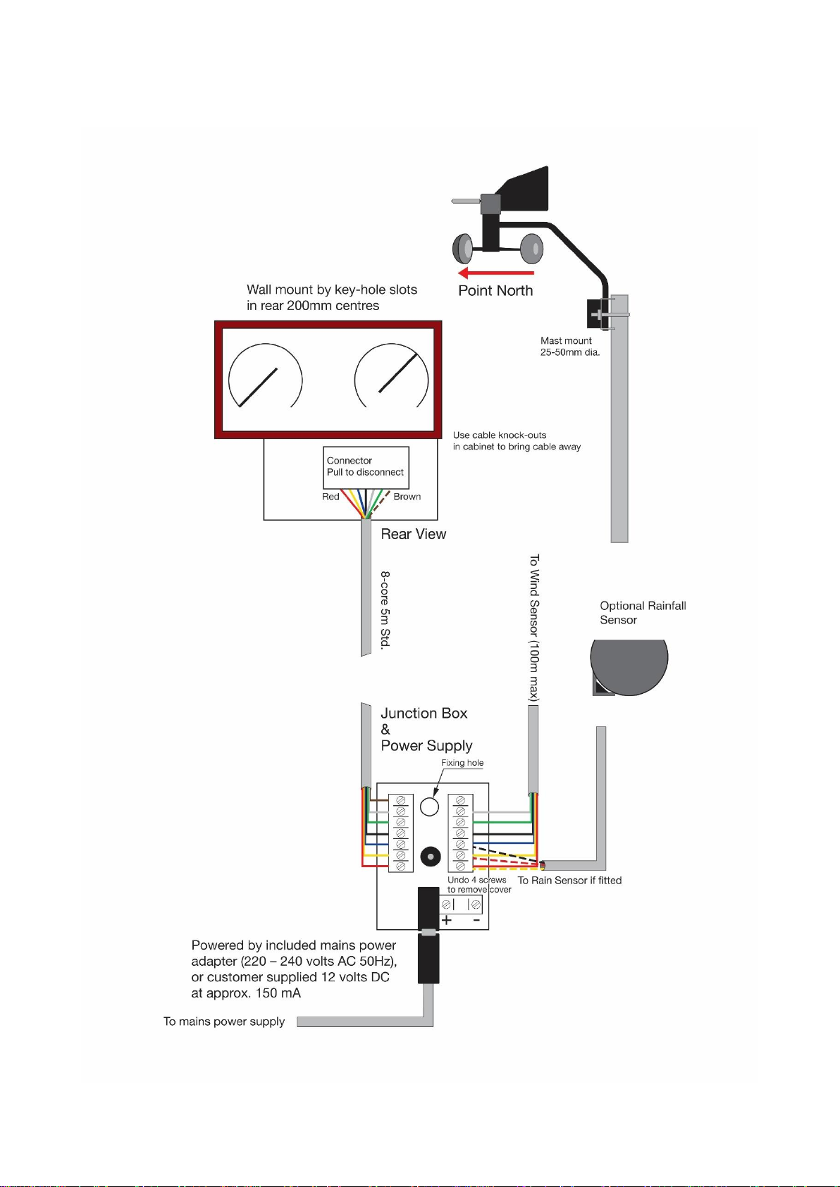
If Wind Direction gives the wrong reading, check that the wind sensor has been mounted to point North. If the
Northerly and North East wind direction lamps are permanently lit, then the wind sensor is not connected to
the instrument or is incorrectly wired. Note that if the wind sensor is incorrectly wired then neither wind speed
nor direction will work.
Wind Speed not working
Check anemometer cups are turning freely and if so that wiring is correct (particularly the blue wire from the
Wind Sensor) and the cable not damaged.
Barometer showing incorrect pressure
The barometer may need adjusting to the pressure at your location. First obtain a pressure reading from a
reliable nearby source such as an airfield or local Met Office. Having done this, locate the adjustment screw
visible through the back panel and using a small screwdriver turn the adjusting screw until the pressure
reading is the same as that obtained locally. Do not attempt to turn the screw more than one turn in either
direction.
Temperature reading inaccurate
If you suspect the temperature reading to be inaccurate, please ensure that the thermometer with which you
are comparing is accurate.
If the temperature reading is only 1 or 2 degrees out, then the display can be recalibrated as follows:
Remove the display from the wall by lifting the unit and pulling forward.
At the back of the display there are three small “dip” switches next to the 8-way cable plug. Turn switch “1” to
the other position. The display should now enter its temperature calibration screen shown in °C. Now use
buttons A & B to increase or decrease the temperature respectively. Switch the “Dip” switch back once the
correct temperature reading has been reached.
Temperature display locked on a fixed temperature
The display may have locked up during installation. Other indications are that none of the buttons located at
the side of the instrument will have any effect on the display. This can sometimes happen and can usually be
corrected by disconnecting the power supply from the mains and leaving for two minutes before reconnecting
again.
Rainfall not being displayed
Check that “Dip” switch 2 has been activated on the rear of the display.
Rainfall not being measured
Check that the rain sensor has not become blocked with leaves or bird droppings etc.
Check also the sensor is mounted horizontally.
Very slowly put 5mL of water (a medicine spoon) into the Rain Sensor and check water is coming out of the
bottom tube a drip at a time. If so, this should give a reading of approximately 1.00 mm on digital display
(ensure reset before starting).
If it still does not work, check that the sensor has been wired correctly and the cable is not damaged. If wired
underground check that rodents have not chewed through the cable.

9
Other LCD Display information
Whenever the rain sensor is connected, the display can be set to “scroll” between the three displays (clock,
temperature and rainfall). This can be done by de-selecting the lower end panel button. The display will then
“Scroll” between each parameter every 5 seconds. To remain on just one parameter, depress the scroll button
while the desired parameter is displayed, e.g. rainfall.
The LCD circuitry utilises a “Super” capacitor as a backup battery to allow for accidental loss of power whilst
still maintaining the clock, temperature min / max, and rainfall readings. This capacitor will automatically
charge whenever the display is powered and should not need replacing unlike a normal battery.
Although the display will go off in the event of power failure, the readings acquired by the display should
remain in memory until the power is restored.
Service
Please contact us for any questions regarding the product or claims, preferably by email.
ACCUR8
Ford Lane Business Park
Ford
West Sussex
BN18 0UZ
UK
Email: info@accur8tech.com
Phone: 01243 558 280
EC Declaration of Conformity
Tempcon Instrumentation Limited declares that the equipment type with item number A8-AWS200 complies
with EMC Directive 204/108/EC. The full text of the declaration of conformity is available on request from the
address above.
Disposal
Dispose of the packaging materials properly, according to their type, such as paper or cardboard. Contact
your local waste-disposal service or environmental authority for information on the proper disposal.
Do not dispose of electronic devices in the household rubbish! As per Directive 2012/19/EC of the European
Parliament on waste electrical and electronic equipment, used electronic devices must be collected separately
and recycled in an environmentally friendly manner.
Do not dispose of batteries and rechargeable batteries with the household waste. You are legally required to
return used batteries and rechargeable batteries. After they are used, the batteries can be returned free of
charge to our point of sale or to a nearby location (for example, retailers or municipal collecting points).
Batteries and rechargeable batteries are marked with a symbol of a crossed-out dustbin and the chemical
symbol of the pollutant. “Cd” stands for Cadmium, “Hg” stands for mercury and “Pb” stands for lead.
Document Version 1.7

10
This page intentionally left blank

11
This page intentionally left blank
Table of contents
Other ACCUR8 Weather Station manuals
Popular Weather Station manuals by other brands

Ventus
Ventus W177 user manual

Bresser
Bresser W-LAN-Weather-Center-6-in-1 instruction manual

TFA
TFA 35.1087 instruction manual

Oregon Scientific
Oregon Scientific WMR968 user manual

Innovative Technology
Innovative Technology ITST-10 owner's manual

Columbia Weather Systems
Columbia Weather Systems Orion Vehicle user manual