Accuspray VMX User manual

©Copyright 2003 Accuspray Application Technologies, Inc. Cleveland, Ohio USA SM-VMX-2001
800-618-6860 or 440-498-9677 Fax: 440-498-9815
VMX
PORTABLE COMPRESSOR HVLP SYSTEM
Owners Manual

2
©Copyright 2003 Accuspray Application Technologies, Inc. Cleveland, Ohio USA
800-618-6860 or 440-498-9677 Fax: 440-498-9815
General Safety
Accuspray's HVLP equipment is for professional use only. Hazards can occur from equipment misuse. Any
misuse of the equipment or accessories, such as over pressurizing, modifying parts, using incompatible
chemicals and fluids, or using worn or damaged parts can cause serious bodily injury, fire, explosion or property
damage. Read, understand and follow all general safety, safety precautions and user instructions before
using your Accuspray equipment.
• NEVER point a spray gun at anyone or any part of the body.
• NEVER place your hand or fingers in front of a spray nozzle.
• NEVER try to stop or deflect fluid leaks with your hand or body.
• NEVER alter or modify any part of this equipment.
• CHECK your spray equipment before each use. Repair or replace worn or damaged parts immediately.
• ALWAYS use AccuSpray replacement parts. Only these parts were designed to work with your equipment.
Safety Precautions
Solvents and coatings can be highly flammable to combustible, especially when sprayed. Adequate exhaust must
be provided to keep the air free of accumulations of flammable vapors. Smoking must never be allowed in spray
areas. Fire extinguishing equipment must be present in the spray area.
Certain materials may be harmful if inhaled or if there is contact with the skin. Follow the requirements of the
Material Safety Data Sheet supplied by the coating manufacturer. Use a respirator whenever there is a chance of
inhaling sprayed material. The mask must be compatible with the material being sprayed and its concentration.
Safety equipment must be NIOSH approved.
Certain solvents containing Methylene Chloride and Trichloromethane are not chemically compatible with
aluminum or zinc. The solvents reaction can become violent or explosive. If you are in doubt whether a coating or
cleaning material is compatible, contact your material supplier.
Improper operation or maintenance may create a hazard. Personnel must be given training. Instructions and
safety precautions must be read and understood. Comply with your local, state, and national codes governing
ventilation, fire protection, operation, maintenance, and housekeeping.
Before first time use of your Accuspray 19C Series Low CFM Spray Gun
• The fluid inlet fitting and the air inlet fitting of your 19C Series Low CFM Spray Gun are not removable
components. Do not remove or attempt to service the fluid inlet fitting or the air inlet fitting.
• Whenever you attach or detach an air hose fitting to the gun's air inlet, use two wrenches. Holding a
wrench on the air inlet fitting will lessen the amount of force applied to the guns internal air inlet tube
when tightening.
• Check the fluid packing and adjustment
• Check the tightness of the fluid nozzle
• Flush the fluid passage with a compatible solvent
• Due to the finer atomization of your 19C Series Low CFM Spray Gun, you may need to slow down your
solvent or hardener speed.

- 3 -
3
©Copyright 2003 Accuspray Application Technologies, Inc., Cleveland, Ohio USA
800-618-6860 or 440-498-9677 Fax: 440-498-9815
V M X®Owners Manual
Introduction:
VMX®is a high output HVLP spray system
designed to handle a wide variety of coatings. This
system offers many advantages; the ability to spray
large quantities of material, less thinning of material,
greater speed, high transfer rates, low overspray,
and high finish quality. The VMX®system consists
of a 2hp oil-less compressor, a 2.5-gallon pressure
pot, and Accuspray’s model 19c low cfm HVLP
spray gun. Please take a few moments to familiarize
yourself with the operations of the VMX®to ensure
best results. Additional help can be obtained
through our technical service line at (800) 618-6860
ext. 191. Thank you for purchasing Accuspray.
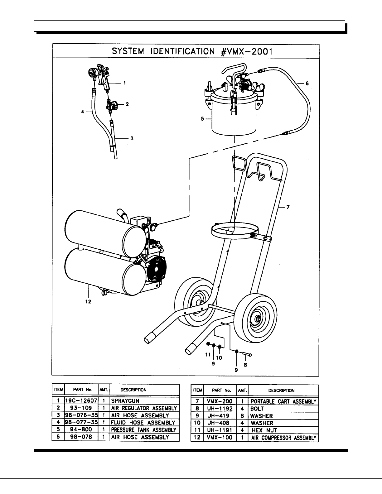
System Contents:
Your VMX system contains:
1- 19c-12607 Low cfm spray gun
1- 93-109 Spray gun air regulator
1- 98-076-35 Fluid hose assembly
1- 98-077-35 Air hose assembly
1- 94-800 2.5-gallon pressure pot with regulator
1- 98-078 Air supply hose
1- VMX-100 Compressor/tank assembly*
1- VMX-200 Cart assembly with pot ring*
*Shipped as a complete unit
See page 4 for a diagram of the system.
Before First Use:
The following tips can help to ensure proper
operation, avoid damage to the system, prevent
personal injury, and extend equipment life.
*Read and follow all safety instructions.
*Read and follow the compressor operations manual
included with this system.
*Always use the proper, grounded extension cord of
appropriate length and gauge (see compressor
manual). Failure to do so voids all warranties,
interferes with compressor operation, and will greatly
shorten the life of the compressor.
* Always fully release all pressure before opening,
cleaning, or servicing any part of this system.
* Always drain compressor air tanks at the end of
the day to avoid corrosion and cut down on moisture
in system air. Conditions may require more frequent
draining depending on environmental factors.
*Keep the air compressor as far away from the spray
area as possible. Extend the air supply line from the
compressor to the pot instead of increasing
extension cord length. Then move the pot closer to
the spray area.
*Always spray at the lowest possible pressure to
correctly atomize your coating. Over-pressurizing
wastes material, increases overspray and works the
unit harder than necessary.
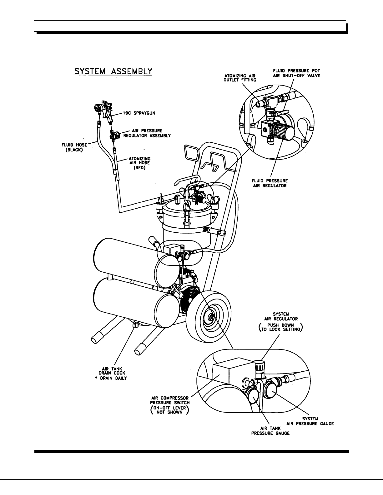
Set Up Instructions:
Diagrams illustrating the following instructions are
located on page 5.
1. Place the pressure pot into the cradle ring on the
cart assembly.
2. Connect the short red air supply hose to the
outlet regulator located on the compressor. This is a
quick coupler connection.
3. Connect the other end of the air supply hose to
the ¼ in. nipple located directly above the gauge on
top of the pressure pot. Fully seat and tighten the
connecting nut. This is a compression fitting and
must be tight to seal. Teflon tape is not necessary.
4. Connect the 35’ red air hose to the nipple just
opposite the connection made at step 3.
5. Attach spray gun regulator to the butt of the spray
gun. Use two wrenches to tighten completely;
failure to do so may damage the air fitting on the butt
of the gun. All connections use compression fittings
and do not require additional Teflon tape.
6. Connect the remaining end of the 35’ air hose to
the bottom of the regulator at the butt of the gun.
7. Connect the black fluid hose to the fluid outlet
fitting located on the top of the pot and connect the
opposite end of this hose to the fitting at the front of
the spray gun. Again, use two wrenches and
completely tighten.
8. Cable ties are supplied to band the fluid and air
hoses together and eliminate line tangle.
9. Check all connections to avoid any leakage.
Start Up/Operating Instructions:
Please refer to the compressor manual for
additional instructions.
1. Plug into appropriate power source.
2. Remove lid from pressure pot, add material to be
sprayed, replace lid and hand tighten until snug.
Always check for a good seal and tighten all bolts
evenly.
3. Turn on the compressor using the on/off switch
located on the pressure switch (see page 5 for
switch location).
4. Compressor will run until air storage tanks are
full. The compressor will stop when air tank
pressure reaches approximately 125 psi. The
pressure can be read at the gauge directly opposite
the on/off switch.
5. Open the pressure pot air supply valve located
on top of the pressure pot directly above the
regulator. When the red handle is up the valve is
open. Close the valve by moving the handle to the
right or left.
6. Slowly turn the dial on the supply air regulator
clockwise until the regulator reads 90 psi. This
regulator is located at the compressor.

- 4 -
4
©Copyright 2003 Accuspray Application Technologies, Inc., Cleveland, Ohio USA
800-618-6860 or 440-498-9677 Fax: 440-498-9815
V M X®Owners Manual
Operation Instructions Cont.:
7. System pressure has now been set. System
pressure is not atomizing pressure or material
pressure. These pressures are independently
controlled at the pot and spray gun respectively.
System pressure ensures smooth operation at both
regulators and compensates for any pressure drop
when system is in use.
8. To set fluid pressure use the regulator on top of
the pressure pot. Make sure to complete step 5 first.
Operating pressure range is between 5 and 50 psi.
Do not exceed 80 psi.
9. To set atomizing air pressure use the regulator
on the bottom of the spray gun. Always adjust
atomizing air with the trigger pulled (active air).
HVLP compliant pressure range is between zero
and 43 psi.
Note: This is a 4.3 to 1 ratio HVLP conversion gun.
43 psi into the spray gun regulator yields 10 psi at
the air cap.
Shut down and Clean Up Instructions:
Always relieve all pressure from the entire system
before attempting any clean up.
1. Turn unit off.
2. Remove pressure from the pot by unscrewing the
pressure relief screw on top of the pot lid.
3. Disconnect the supply air hose at the compressor
using the quick disconnect.
4. Always flush the system with a solvent that is
compatible with the coating you have sprayed.
5. Pressurize the system to flush the fluid line and
spray gun.
6. Always drain all fluid from system and store dry.
7. Always drain all air from tanks and open drain
cock to remove and prevent moisture build up.
8. See the spray gun portion of this manual for
additional care instructions.
Pressure Settings:
The following instructions are to be used as
guidelines on how to correctly set the pressure on
your VMX®system. Proper settings are crucial to
achieve quality finishes while cutting down on
overspray and compressor run time. Always keep
the outlet pressure regulator (located at the
compressor) as close to 90 psi as possible. This
regulates system pressure and keeps both the fluid
and air regulators operating smoothly.
Fluid pressure should be set first; this is done using
the regulator located on top of the pressure pot,
which controls fluid pressure only. A good rule of
thumb is to shut off the atomizing air completely
while adjusting fluid pressure. This is done by
turning the spray gun regulator to zero.
Trigger the gun fully open and hold spray gun
parallel with the floor. Increase fluid pressure until
you achieve a 6 to 12 inch fluid stream that is
parallel with the floor. The stream should hold
steady 6 to 12 inches and then curve towards the
floor. The pressure needed to achieve this stream is
your proper fluid pressure and will vary greatly
depending on the viscosity of the fluid used as well
as the size of the atomizing kit used.
Adjust atomizing air at the spray gun air regulator
(located directly below the gun). Once fluid pressure
is set simply increase air pressure until you have a
uniform fully wet pattern when the gun is held 6 to 8
inches from the spray surface. Maximum gun
pressure should not exceed 43 psi active air. Gun
pressure is always measured at active air levels
(gun triggered open). This gun has a two-stage
trigger pull; the first half of trigger travel releases air,
fluid is released later. This lets you adjust active air
levels without triggering fluid. Minor atomizing
adjustments are handled at the spray gun; see the
spray gun portion of this manual for instructions.
Remember, proper patterns are achieved through
a balance of air pressure and fluid pressure. These
pressures vary greatly from coating to coating and
can be affected by temperature. Pressures may
also need to be increased if hose length is increased
or when spraying from ladders at increased heights.
Do not add fluid hose. Extend the air supply hose
between the compressor and pressure pot to
increase overall distance from the compressor
system.
Listed below are some common pressure ranges
for popular materials.
Lacquers: Fluid Pressure: 8 to 15 psi
Air pressure: 15 to 22 psi
Oil-based Enamels: Fluid pressure: 12 to 25 psi
Air pressure: 17 to 30 psi
Most Latexes: Fluid pressure: 25 to 45 psi
Air pressure: 25 to 43 psi
Multi-color Coatings: Fluid pressure: 25 to 45 psi
Air pressure: 20 to 43 psi
These pressures are starting points only. Always
spray at the lowest possible pressure. Thinning is
not required on most materials. However, we
recommend heavy latexes be thinned between 5
and 15 percent to improve system performance. For
best results use the proper atomizing set for the
viscosity of the material being sprayed as follows.
Fine finish (light bodied): Prokit-35
Medium (oils and latex enamels): Prokit-37(supplied)
Heavy (multi colors and latex): Prokit-36

- 5 -
5
©Copyright 2003 Accuspray Application Technologies, Inc., Cleveland, Ohio USA
800-618-6860 or 440-498-9677 Fax: 440-498-9815
V M X®Owners Manual

- 6 -
6
©Copyright 2003 Accuspray Application Technologies, Inc., Cleveland, Ohio USA
800-618-6860 or 440-498-9677 Fax: 440-498-9815
V M X®Owners Manual

- 7 -
7
©Copyright 2003 Accuspray Application Technologies, Inc., Cleveland, Ohio USA
800-618-6860 or 440-498-9677 Fax: 440-498-9815
V M X®Owners Manual
Gun Adjustments
The fan size is regulated by the fan adjustment knob
located on the side of the gun. With the gun pointed
at your target, turn the knob toward you until it stops.
This is the fully closed position. Turning the knob
away from you increases the fan air.
The fluid is controlled by the needle adjustment
screw located at the rear of the gun. Turning the
knob clockwise (right) will close down the fluid flow,
minimizing needle travel (trigger pull). Turning the
knob counterclockwise (left) will increase the fluid
flow, maximizing needle travel (trigger pull).
With 3 threads of the needle adjustment screw
showing from the gun body (approximately 7
counterclockwise turns from closed) you will have
full needle travel.
Please note that when closing down the needle
adjustment screw, when the needle travel has
stopped, further tightening will damage the needle
tip and will not aid in adjustment.
Spray Technique
Proper spray technique is very important to achieve
a good finish. Always spray at a distance of 6 to 8
inches from your target. Keep the gun parallel to
your target throughout the entire pass. More detailed
spraying can be done with the gun as close as 1
inch from the target. Make sure your wrist remains
firm during each pass.
Trigger your gun only after your pass begins, and
release the trigger before stopping your motion. Do
not angle the gun upward or downward while
spraying. Angled spraying will develop an uneven
paint buildup. Overlap your passes approximately
50% for an even finish. Always be certain to thin
your material with the proper solvent, and to follow
the recommendations of the material's manufacturer.
Hand Gun Use

- 8 -
8
©Copyright 2003 Accuspray Application Technologies, Inc., Cleveland, Ohio USA
800-618-6860 or 440-498-9677 Fax: 440-498-9815
V M X®Owners Manual
Troubleshooting

- 9 -
9
©Copyright 2003 Accuspray Application Technologies, Inc., Cleveland, Ohio USA
800-618-6860 or 440-498-9677 Fax: 440-498-9815
V M X®Owners Manual
Daily Maintenance
Your Accuspray HVLP Gun is made from cast
aluminum, and it contains aluminum components.
Certain solvents containing Methylene Chloride and
Trichloromethane are not chemically compatible with
aluminum. If you are in doubt whether a coating or
solvent is compatible, read the Material Safety Data
Sheet, or contact your material supplier.
It is very important to clean your gun and cup after
every use. The fluid passage can be cleaned by
adding a small amount of solvent to a clean cup,
pressurizing the cup, and triggering the gun. Do this
with the air cap removed so you may recapture the
spent solvent for proper disposal.
The air cap should be cleaned by soaking, or by
using a soft brush. Never use a hard tool that may
damage the air cap holes. Clean the air cap holes
with a wooden tooth pick or pipe cleaner. The
smallest amount of damage to the air cap holes can
effect the spray pattern.
Your gun and cup may be cleaned in a gun washer.
Limit the time in the gun washer to a maximum of 5
minutes. Some solvents may enter the through the
air inlet fitting. This will not damage the gun, and the
excess solvent may be blown out with air.
Lubrication
After every cleaning of the gun, you should lubricate
the moving components. Lubricate with Accuspray
Gun Lube P/N 91-170.
Component Replacement
With regular cleaning and lubrication, complete
disassembly of your gun should seldom be required.
When it becomes time for a complete overhaul, or a
part requires replacement, please follow these
instructions:
General
Close your air source down. Remove the air hose
from the gun. Dispose of any unused paint, flush
and clean the gun.
Atomizing Set
With the retaining ring and air cap removed, pull and
hold the trigger, unscrew the fluid nozzle using your
Accuspray Gun Wrench and remove the fluid nozzle.
Release the trigger and unscrew the needle tip with
your fingers. Remember to retract the needle when
re-installing the fluid nozzle.
To remove the needle shaft, unscrew and remove
the needle adjustment screw and the needle
adjustment spring. Pull the needle out of the gun
with your fingers. If the needle does not pull out
freely, loosen the packing nut. Your gun wrench will
accomplish this with the trigger still attached to the
gun.
Trigger Removal
Locate the 2 E-clip's on the side of the trigger. Slide
them off with a flat-blade screwdriver. The trigger
pivot pin (upper), and the trigger pin (lower) will now
slide out. The trigger is now free to be removed.
Packing Nut Spacer and Packing
Unscrew and remove the needle adjustment screw
and the needle adjustment spring. Pull the needle
out of the gun with your fingers. If the needle does
not pull out freely, loosen the packing nut. Remove
the packing nut with your gun wrench. The
compression spring, spacer, needle guide, and seal
should fall freely from gun. If you experience
difficulty with removal, remove trigger pin and firmly
tap the rear of the gun on a block of wood. Then
remove the seal with an o-ring pick or similar narrow
instrument.
Maintenance

- 10 -
10
©Copyright 2003 Accuspray Application Technologies, Inc., Cleveland, Ohio USA
800-618-6860 or 440-498-9677 Fax: 440-498-9815
V M X®Owners Manual
Fan Air Knob
To remove the fan air knob, and to lubricate the fan
air stem threads, use a 3/64" hex key. Unscrew and
remove the fan air adjustment screws, and lift off the
fan air adjustment knob. Using your gun wrench,
unscrew and remove the fan air fitting from the gun
body. The fitting will lift out from the gun body as a
subassembly. See Figure 1. The subassembly may
be replaced, or you may proceed with further
disassembly. See Figure 2.
Caution
It is not recommended that the fan air fitting be
removed frequently. The component contains a
Teflon O-ring, and does not require regular
lubrication. Lubricate only when a new component is
installed.
The subassembly may now be disassembled by
removing the E-clip from the fan air stem, with a
small flat-blade screwdriver. With the e-clip
removed, back out the fan air stem from the fan air
fitting. The O-ring may now be removed and
replaced, and the subassembly can be
reassembled, and placed back into the gun .
Valve Rebuild
With regular cleaning and lubrication, complete
disassembly of your gun should seldom be required.
Good lubrication practices should be in place to
ensure this.
Valve rebuild is a two step procedure. Step one
involves the removal and replacement of the valve
spring. You would do this if you were experiencing a
sluggish trigger return. To remove the valve spring,
unscrew and remove the valve cap. See Figure 3.
At this stage, you can also remove and replace the
O-ring for the valve cap. For complete valve rebuild
instructions, continue reading.
Step two involves completely removing the valve
from the gun body. Before you can proceed, the
needle shaft and the trigger must be removed. We
will also assume that the valve cap, the valve spring,
and the O-ring have already been removed. See
Figures 3 through 6.
Grasp the valve stem and pull it forward. Note that
the removal of the valve stem cap is not required.
Removal and replacement of the valve stem cap will
be covered later in this section. The valve stem will
pull out from the valve seat, and out of the gun
through the seal housing.
The valve seat can be removed from the gun by
gently reinserting the valve stem into the seal
housing to "unseat" the valve seat. The valve seat
will drop out of the valve cavity. See Figure 5.
Seal Housing Replacement
Using your gun wrench, unscrew and remove the
seal housing. The seal housing subassembly
contains an internal snap ring. This is the only area
that a special tool is required. The snap ring requires
a size 100 tool. With the snap ring removed, lift out
the spacer, the lip seal, and clean the seal housing
cavity.
Before reassembling the seal housing, note the
orientation of the lip seal. The open end of the lip
seal is to be placed into the seal housing. Pack the
seal housing with petroleum jelly. The lip seal will be
properly installed when you feel a positive lock, and
it is resting level. Reinstall the spacer and the snap
ring. See Figure 6.
Valve Stem and Valve Seat Replacement
Drop a new valve seat into the valve cavity (open
end down) See Figure 7. Gently press down on the
valve seat to align it in the cavity. A long thin object
such as a pen works well for this. See Figure 8.
Reinstall the O-ring, valve spring, and valve cap.
See Figure 9.
Gently push the valve stem back into the valve seat
through the seal housing. See Figure 10. You will
know that the installation is correct and complete
when the spring return action is smooth. As a final
seating procedure, depress the valve stem as far
back as it will go, then release it. Lubricate the valve
stem.
Valve Stem Cap Replacement
To remove the valve stem cap, remove the valve
stem from the gun. Place the valve stem in a vice
equipped with soft jaws. With pliers, pull off the valve
stem cap.
To replace the valve stem cap, leave the valve stem
in the vice. Hold the valve stem cap with needle
nose pliers, and lightly tap it down with a wooden or
rubber mallet. The valve stem cap will seat onto the
shoulder of the valve stem. Always replace the valve
stem cap with a new one.
The trigger and remaining components may now be
reassembled, and your gun is ready to be placed
back into service.
Maintenance

- 11 -
11
©Copyright 2003 Accuspray Application Technologies, Inc., Cleveland, Ohio USA
800-618-6860 or 440-498-9677 Fax: 440-498-9815
V M X®Owners Manual
Maintenance

- 12 -
12
©Copyright 2003 Accuspray Application Technologies, Inc., Cleveland, Ohio USA
800-618-6860 or 440-498-9677 Fax: 440-498-9815
V M X®Owners Manual
Cups and Pots
It is very important to clean all of your equipment
after each use. Before opening and cup or tank,
relieve the air pressure.
Clean your cup or pot with a suitable solvent, always
read the Material Safety Data Sheet for any
chemical you are using.
Check and clean cup gaskets after every use.
Lubricating cup gaskets with Accuspray gun lube will
extend the life of the gasket, and keep it sealing
properly.
If using a 1-quart cup, check the diaphragm and the
spring clip regularly.
When replacing components, use only Accuspray
genuine replacement parts, only these parts were
designed to work with your Accuspray equipment.
For information on genuine Accuspray replacement
parts, contact your distributor or call Accuspray, a
professional technical staff is on hand to meet your
spraying needs.
Coating Information
Coating Name Viscosity Flow Rate Nozzle Air Cap Result

- 13 -
13
©Copyright 2003 Accuspray Application Technologies, Inc., Cleveland, Ohio USA
800-618-6860 or 440-498-9677 Fax: 440-498-9815
V M X®Owners Manual

- 14 -
14
©Copyright 2003 Accuspray Application Technologies, Inc., Cleveland, Ohio USA
800-618-6860 or 440-498-9677 Fax: 440-498-9815
V M X®Owners Manual

- 15 -
15
©Copyright 2003 Accuspray Application Technologies, Inc., Cleveland, Ohio USA
800-618-6860 or 440-498-9677 Fax: 440-498-9815
V M X®Owners Manual

- 16 -
16
©Copyright 2003 Accuspray Application Technologies, Inc., Cleveland, Ohio USA
800-618-6860 or 440-498-9677 Fax: 440-498-9815
V M X®Owners Manual

- 17 -
17
©Copyright 2003 Accuspray Application Technologies, Inc., Cleveland, Ohio USA
800-618-6860 or 440-498-9677 Fax: 440-498-9815
V M X®Owners Manual

- 18 -
18
©Copyright 2003 Accuspray Application Technologies, Inc., Cleveland, Ohio USA
800-618-6860 or 440-498-9677 Fax: 440-498-9815
V M X®Owners Manual

- 19 -
19
©Copyright 2003 Accuspray Application Technologies, Inc., Cleveland, Ohio USA
800-618-6860 or 440-498-9677 Fax: 440-498-9815
V M X®Owners Manual

- 20 -
20
©Copyright 2003 Accuspray Application Technologies, Inc., Cleveland, Ohio USA
800-618-6860 or 440-498-9677 Fax: 440-498-9815
V M X®Owners Manual
To order additional copies of this manual, call Accuspray
Customer Service at 1-800-618-6860
or fax your request to (440) 498-9815
Visit us online at www.accuspray.net
Request Literature Number SM-VMX-2001
LIMITED WARRANTY
A
ccuspray warrants all equipment manufactured by and bearing its name to be free from defects in material and
workmanship on the date of sale by an authorized Accuspray distributor to the original purchaser for use. Excep
t
as expressly stated in any Accuspray Special, Extended or Limited Warranty provided in writing by Accuspray,
A
ccuspray shall for a period of twelve months from the date of sale, repair or replace any part of the equipmen
t
proven defective. This warranty applies only when the equipment is installed, operated and maintained in
accordance with Accuspray's written recommendations.
This warranty does not cover, and Accuspray shall not be liable for, normal wear and tear components, an
y
malfunction, damage, or wear caused by faulty installation, misapplication, abrasion, corrosion, inadequate o
r
improper maintenance, negligence, accident, tampering, alteration or substitution of non-Accuspray componen
t
parts. Nor shall Accuspray be liable for malfunction, damage, or wear caused by the incompatibility with
A
ccuspray equipment of structures, accessories, equipment or materials not supplied by Accuspray, or the
improper design, manufacture, installation, operation or maintenance of structures, accessories, equipment o
r
materials not supplied by Accuspray.
This warranty is conditional upon the prepaid return of the equipment claimed to be defective to an authorized
A
ccuspray Service Center or to Accuspray, to verify the claimed defect. If the claimed defect is verified to be
covered by this warranty, Accuspray will repair or replace free of charge any defective parts and the equipmen
t
will be returned to the original purchaser freight paid. If inspection of the equipment does not disclose a valid
warranty claim, repairs, if any, will be made at a reasonable charge to the purchaser. These charges may include
the cost of inspection, parts, labor, and return transportation.
Disclaimer and Limitations. The terms of this warranty constitute Accuspray's sole obligation and purchaser's
sole and exclusive remedy and are in lieu of any other warranties (express or implied), including warranty o
f
merchantability or warranty of fitness for a particular purpose, or any non-contractual liabilities, including produc
t
liabilities based on negligence or strict liability. Every form of liability for direct, special or consequential damages
or loss is expressly excluded and denied. In no case shall Accuspray's liability exceed the amount of the
purchase price. Any action for breach of warranty must be brought within two (2) years of date of sale.
Equipment Not Covered by Accuspray Warranty. Accuspray makes no warranty, and disclaims all implied
warranties of merchantability and fitness for a particular purpose with respect to accessories, equipment,
materials, or components sold but not manufactured by Accuspray. These items sold but not manufactured b
y
A
ccuspray (such as electric motors, switches, hose, etc.), are subject to the warranty, if any, of thei
r
manufacturer. Accuspray will provide purchaser with reasonable assistance in making any claim for breach o
f
these warranties.
Accuspray is a registered trademark of
Accuspray Application Technologies, Inc.
All other products named in this publication are either trademarks or registered
Trademarks of their res
p
ective owners.
Table of contents