Accutron I.S. DRIFT User manual

I.S.
I.S.I.S.
I.S.
DRIFT /
DRIFT /DRIFT /
DRIFT /
I.S.
I.S.I.S.
I.S.
FAN
FAN FAN
FAN
Intrinsically Safe Airflow Metering Systems
Technical / Operations
Manual
ManualManual
Manual
MODEL:
ACCIS-SYS-002-DR (Drift)
ACCIS-SYS-002-FN (Fan)
V07.10.2020
For more information on our products visit www.accutroninstruments.com
Contact us by email: [email protected]m
Or by phone: 705- 82-0814

1
IMPORTANT NOTICE
The Accutron IS family of instruments is the exclusive copyright properties of Accutron Instruments Inc.
Accutron Instruments Inc. reserves the right to make changes to the Accutron products and manuals without further
notice to improve reliability, function or design. Accutron Instruments Inc. does not assume any liability arising out
of the application or use of any product described herein, nor does it convey any license under its patent rights, nor
the rights of others.
The documentation supplied is for the purpose of furnishing users of Accutron products with technical information
on how to install, use, and maintain the various instruments. It is forbidden to use any Accutron documentation for
any other purpose that may be detrimental to the interests of Accutron Instruments Inc.

2
Table of Contents
S E C T I O N 1 - G E N E R A L I N F O R M A T I O N
The Manual ................................................................................. 4
Safety Guidelines ............................................................................ 5
Information About Your System .................................................. 5
Specifications for the Accutron IS Drift/Fan .................................. 6
S E C T I O N 2 - I N S T A L L A T I O N
System Explanation ........................................................................ 7
Choosing a Location ....................................................................... 8
Mounting the Display ..................................................................... 8
Mounting the Sensors ..................................................................... 9
Connecting the Sensor Cables ........................................................ 9
S E C T I O N 3 - P R O G R A M M I N G
Navigation Buttons ......................................................................... 10
Programming Data Sheet ................................................................ 11
Auto Range Feature ........................................................................ 12
Quick Start Programming ............................................................... 13
Menu Flow Chart ............................................................................ 14
Detailed Menu Setup....................................................................... 15
S E C T I O N 4 - M O D B U S
RS485 Settings ............................................................................... 19
Modbus Register ............................................................................ 19
Modbus Connection ........................................................................ 20
S E C T I O N 5 - T R O U B L E S H O O T I N G
FAQ (Frequently Asked Questions) .............................................. 21
Troubleshooting Flowchart ............................................................ 23

3
A P P E N D I X A
Glossary ................................................................................. 25
Equations ................................................................................. 26
Accutron IS Drift Parts List ............................................................ 27
Accutron IS Fan Parts List.............................................................. 28
Component Check List ................................................................... 29
A P P E N D I X B - D I A G R A M S
Wiring Diagram .............................................................................. 30
Enclosure Dimensions .................................................................... 31
Accutron IS Drift Transducer Dimensions ..................................... 32
Accutron IS Drift Mounting Dimensions ....................................... 33
Accutron IS Fan Transducer Dimensions ...................................... 34
Accutron IS Drift System ............................................................... 35
Accutron IS Fan System ................................................................ 36

4
Section 1 - General Information
The Manual
Refer to this manual for proper installation, operation and maintenance of the Accutron IS
Instrument.
Special attention must be paid to warnings and notices highlighted from the rest of the text by
gray boxes.
Warning: means that failure to observe the necessary precautions can result in death, serious
injury, and/or considerable material damage.
Note: means important information about the actual product or a specific section of the
operating manual.
•
These instructions do not claim to cover all details or variations in equipment, or to provide
for every possible contingency that may arise during installation, operation, or maintenance.
•
For further information or to resolve issues not covered in the manual, consult your Accutron
representative.
•
The contents of the manual shall not become part of or modify any prior or existing
agreement, commitment or relationship. The Sales contact contains the entire obligation of
Accutron Instruments Inc. The warranty contained in the contract between the parties is the
sole warranty of Accutron Instruments Inc.
IMPORTANT: All specifications are subject to change without notice. Please ensure that
any safety-related information is confirmed with a qualified Accutron Instruments
representative.

5
Safety Guidelines
Warning notices must be observed to ensure personal safety as well as that of others, and to
protect the product and the connected equipment.
This device/system should only be set up and operated in conjunction with this manual.
Qualified personnel are only authorized to install and operate this equipment in accordance with
established safety practices and standards.
Warning: This product can only function properly and safely if it is correctly transported,
stored, installed, set up, operated, and maintained.
Note: Always use product in accordance with specifications.
Information About Your System
When you first open your Accutron IS unit, be sure to record the following:
Model Number (located behind door): _______________________________
Serial Number (located behind door): _______________________________
Code version (displayed on startup): _______________________________
Note: If you need to contact Customer Service, this information will be beneficial.

Specifications for the Accutron IS Drift/Fan – Airflow Sensor
Connections: Screw terminal Block Type
Transducers: 3 ½” (Dia.) X 9 1/8” (L)
Display Readout: 16 Characters LCD display.
Each digit is 0.57” (H) X 0.24” (W)
Power Supply: 12.6 VDC intrinsically safe power supply
Power Consumption: < 3.3 watts
Input Power: 12.6 VDC
Display Units: M/S, CFM, KCFM, M**3/S, FPM
Temperature range: -40°to +60°Celsius
Accuracy: 2% FS or ±0.05 M/S (whichever is greater)
Output type: 4-20mA
Output modes: Normal, Reverse, or Split (used for bi-directional measurements)
Fault/Alarm Output: (Not available at this time)
Sensor cables: 100 feet STD (sensor-to-box). Custom cables up to 500ft.
Connectors: Stainless Steel, with O-ring seals. IP68 rated.
Sensor Mounting: Industrial CATV pan and tilt mount (non-aluminum)
Tunnel sizes: Can accommodate a face-to-face distance of 70 feet.
Programming: User interface onboard using navigation buttons.
Max Airflow: 0 to 40 m/s and higher (essentially no practical upper limit)
Bi-directional
Power Supply port parameters (J1): Ui = 12.6V, Ii = 2.5A, Ci = 0uF, Li = 0uH
Isolated Modbus port parameters (J3): Ui = 5.88V, Ii = 3.25A / 0.5A thermal, Ci =0.3uF, Li = 0uH
Isolated 4-20mA Output port parameters (J2): Ui = 28V, Ii = 93mA / 106mA thermal, Ci = 1uF, Li = 5uH

7
Section 2 – Installation
System Explanation
The Accutron airflow sensors are compact and reliable instruments, especially designed for
measuring airflows in mine environments. The Accutron IS Drift System is for airflow
measurements in mine drifts whereas the Accutron IS Fan System is for measuring the flow
output of large mine fans. Each system consists of an Indicating Transmitter, cabling and two
“ultrasonic sensor” assemblies.
The ultrasonic sensor assemblies are installed in the drift diagonally (one further upstream than
the other) with an “imaginary line” between them intersecting the airflow at a typical angle of
120 degrees.
Ultrasonic pulses are sent back and forth between the transducers across the drift, traveling
through the air current. Let “TA-B” be the time taken for the signal to travel from Transducer Ato
Transducer B, and “TB-A” be the time taken for the pulse to travel from Transducer Bto A. The
control unit accurately measures the time-of-flight for each direction. The difference between
the measured times (TA-B – TB-A) is directly proportional to the airflow. In the case of no moving
air, TA-B equals TB-A and there is no time difference because there is no airflow.
The Accutron IS first internally computes the average velocity of the air in Meters/Sec. In order
to obtain air volumes, the area of the drift is entered into the settings menu (during
programming), along with your selection of measurement units. The system then displays air
volumes in the units selected. Common units used in mining applications are KCFM and
M**3/S, other units may also be displayed to measure the air velocity (Meters/ sec, Feet / Min).
After installation in the drift, measurements are made (area, baseline distance, Face-to-face
distance). Using the navigation buttons, these parameters are entered into the unit.
These parameters are retained in non-volatile Flash memory in the Accutron. Whenever the
Accutron powers up, this information is automatically reloaded.
The system can easily measure air velocities in excess of 1,000,000 cfm with a precision better
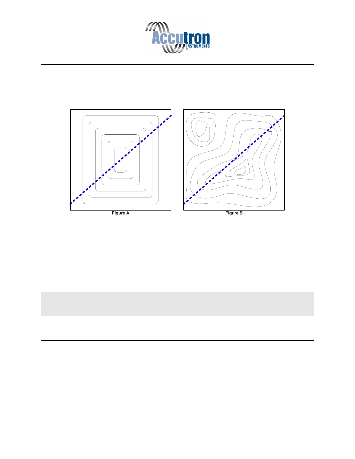
than any other conventional methods, as well as low velocity conditions, i.e. 1m/s. In addition,
since the system is able to sample across the entire drift, readings are more representative than
“single point” measurements. The Accutron takes into account the fact that there is a
“distribution profile” for the air in the drift, making it superior to other types of measurement
methods for fixed installations.

8
Choosing a Location
The best location to install the instrument is in a straight section of tunnel that is at least 3 tunnel
widths long. In such a section, the airflow distribution will be well behaved with a maximum
airflow in the center and minimum airflow on the sides (Figure A). We should try to avoid
locations where the airflow is concentrated in one of the corners (Figure B).
The imaginary line between the Accutron sensors works like a “virtual pitot tube” and all flow
measurements occur along this line. In practice, best results are produced when this “imaginary
line” passes through the center of the tunnel, slicing through the airflow distribution profile in a
representative way.
It is also a good idea to carry out and record a 9-point manual airflow survey to verify the airflow
distribution and identify it as a suitable location.
Note: If we need to measure airflow in a less-ideal location. We may need to manually adjust
the calibration correction factor to give accurate flow readings. In this case, the instrument
would be calibrated against a handheld anemometer.
Mounting the Display
When planning to mount the control unit, you must take into consideration the availability of the
power source, the 4-20mA output signal, i.e. PLC connection, and the sensor cable lengths. In
most cases the control box is mounted on the wall in an electrical room. Extended sensor cable
lengths are available for distances greater than 100 feet.

9
Mounting the Sensors
When planning a mounting location for the wall mount sensors, we recommend mounting one
sensor near the top of the drift or duct and the other sensor located near the bottom downstream
from the first on the opposite side, with an “imaginary line” between them intersecting the
airflow at a typical angle of 120 degrees.
Airflow
End View Plan View
Illustration of typical mine drift installation
Downstream
Sensor
Upstream
Sensor Upstream
Sensor
Downstream
Sensor
Face to Face
Once the mounting brackets are installed, thread the sensors onto the mounts and align them at
each other using the pan/tilt adjustment on the bracket.
Connecting the Sensor Cables
A common mistake made is improperly installing the sensor cables. These must be threaded all
the way to ensure proper functionality.

10
Section 3 – Programming
Navigation Buttons
•To program the settings the programming switch must be in the PROG position.
•The LED display will show CONFIG.
•There are 5 buttons. Up, down, left, right, and Select/Enter.
•Use the up and down buttons to select a specific menu or option.
•To change a value, press Select/Enter to enter Edit mode. Up/Down will increment or
decrement your value. Left/Right will let you shift the cursor to the side. The numbers
cycle through 0-9 including a period for decimal values. Press the Select/Enter button
again to exit the edit mode.
•To save and run, keep navigating through the menu until you reach the main menu.
There, you will be able to select either SAVE/RUN or UNDO/RUN. Press the
Select/Enter button.
•The display will read SWTCHOFF. Return the programming switch into the RUN
position.

11
Programming Datasheet
Before actually programming the Accutron IS, it is a good idea to record the parameters in the
following form. The form should also be filed for future reference.
Menu Option Default Setting New Setting Entered
Configuration Menu
(1A) Flow units A (M/S)
(1B) Linear units A (Meters)
(1C) Face to face distance 0.0
(1D) Baseline distance 0.0
(1E) Cross section area 0.0
(1F) Air flow direction A (Normal sign)
(1G) Zero flow cutoff 0.0
(1H) Instrument full scale 1000.0
(1I) 4-20mA over range A (Saturate/Clipping)
(IJ) Obstruction/fault
timeout in minutes
100 (disabled)
(1k) 4-20mA mode A (0V 0% 2V 100%)
(1L) Moving average 15
Advanced Menu
(2A) Calibration Correction 1.0
*(2B) Noise filter 0
*(2C) Wave detection low
threshold
20
*(2D) Wave detection high
threshold
70
*(2E) Dynamic range
limiting factor
10
*(2F) Hysteresis length 10
(2G) XDUC Gain D (4)
(2H) Moving average type B (First reading)
*(2I) Alternate updates B (Enabled)
*(2J) Envelope Mask 0
Diagnostics Menu
(3A) Address 1
(3B) Baud Rate B (19200)
(3C) Parity A (None)
(3D) Diagnostic output A (Envelope detect)
Note: * Indicates parameters that should be left at default.

12
Auto Range Feature
The Accutron IS comes with a unique feature called auto ranging. It is a quick and easy way to
install your setup without measuring your face-to-face distance. To use this feature, you must do
the following:
1. Make sure that all cables and wires are attached and safely secured.
2. Power the Accutron IS.
3. To start the auto range function, enter a value of 0 in the face-to-face menu. This will
force the Accutron IS to begin auto ranging.
4. Save the settings and restart the system.
5. Upon restart, the display will read “Accutron”, followed by the software version.
6. The display will now read “RANGE0-0” while the transducer sensors receive and send
signals from one another. The display will change depending on the distance.
7. Once the distance has been determined, the display will now be displaying the airflow
readings.
Note: The auto range feature works best in non-gusty conditions. To skip auto range, power on
or reset the unit with the program switch in the PROG position to enter the configuration menu.

13
Quick Start Programming
These step-by-step instructions show you how to quickly program the Accutron IS unit using
most of the default settings.
1. Move the program switch from the RUN position to the PROG position. The display
should read CONFIG.
2. Press Enter to continue. 1A will be displayed.
3. Press Enter. Use up and down to select which flow units to be used. Default is m/s. View
chart for options on page 14. Press Enter to select units.
4. Press Down until 1B is displayed .Press Enter. Use up and down to select which units of
measure you will be using, A for feet or B for meters, then press enter to select.
5. Press Down until 1C is displayed. Press Enter. This is where you will enter your face to
face distance in feet or meters (depending on choice used in step 4) using up and down to
change the number, and left and right to change the digit. Once completed press Enter.
6. Press Down until 1D is displayed. Press Enter. This is where you will enter your
baseline measurement using the same method as step 5.
7. Press Down until CONGIF re-appears. Press Down until SAVE/RUN is displayed and
press Enter. SWITCH OFF will appear. Move the program switch to RUN position.
SYSTEM RESET will appear. Press the Reset Button on the board.
Note: The Accutron IS should now run properly with the above conditions. For a more detailed
explanation regarding the setup, refer to page 15 “Detailed Menu Setup”

14
Menu Flow Chart

15
Detailed Menu Setup
Configuration Menu

1

17
Advanced Menu

18
Diagnostics Menu

19
Section 4 – Modbus
The RS485 interface in the Accutron IS is optically isolated from the rest of the unit. This is why an
external source of 5VDC is required.
Note: Do not poll faster than every 500ms.
The default Modbus RS485 settings are:
Modbus Address: 1 (3A)
Baud Rate: 19200 (3B)
Parity: None (3C)
Stop Bits: 1
These settings can be changed using the navigation buttons located on the main circuit board. Refer to
the flow chart on page 14. Under the diagnostics menu, sections 3A, 3B and 3C all deal with adjusting
the Modbus settings.
Modbus Register
To change unit ID, go into your menu under Diag, option 3A. To change your baud rate, go to Diag,
option 3B. To change parity, go to Diag, option 3C.
Register Addr.
#
Description
Type
R/W
Comment
40001
0,1
Airflow reading
float
Read only
40003
2
Airflow reading
int
Read only
0.1 unit precision
40004
3
Flow units
unit
Read only
See below for more details
40005
4,5
4
-
20mA
output
float
Read only
40007
4
-
20mA
output
int
Read only
0.001 unit precision
40008
7
Error code
unit
Read only
See below for more details
F ow Units (Register 40004)
•0 = m/s
•1 = kcfm
•2 = cfm
•3 = m*3/s
•4 = fpm
•5 = usec
Airf ow Reading (40003), and 4-20mA output (40007)
The range for these registers is from -327 8 to 327 7. Anything greater than these values will default to
the maximum.
Error code (Register 40008)
•0 = good reading
•10 = obstruction. Check sensors
•20 = above full scale
This manual suits for next models
3
Table of contents
Popular Accessories manuals by other brands

Tait
Tait TB8100 user manual

Silvercrest
Silvercrest SPB 2.6 A1 User manual and service information

SSC-LUXon
SSC-LUXon PALISO Assembly & operating instructions

MOBILE-ALERTS
MOBILE-ALERTS MA10660 quick reference

PLX Devices
PLX Devices Legion 5.500mAh user manual

Sun Power
Sun Power CryoTel Series operating instructions