ACDC RAPTOR Mounting instructions

Installation Instructions
and
User Guide
Garage Door Driver Ⅰ
1200N
WARNING
Please read the manual carefully before installation and use. The installation
of your new door opener must be carried out by a technically qualified or
licensed person. Attempting to install or repair the door opener without
suitable technical qualification may result in severe personal injury, death and
/ or property damage.
RAPTOR

CONTENTS
Important safety recommendations..……………………..………….………………..………......…..1-2
Basic function introduction………..…………………..…………………………………...……………...3
Special function introduction………….………………………………..………….………….…………..3
Installation……….……………………………………………………..……………….…….…………….4
Installation (aluminum track) ……..….……………………………..…………….………….…..……..5-6
Installation (one-piece steel track)………………….……………………………………………….…..7-8
Installation (sectional steel track)......…………….………………..……...….………….…………....…9
Installation recommendations…………………………………………..……………….………………..10
Basic function setting…………………………………………………..……………………...…….....11-12
.
Special function introduction (optional)…………..……………………………..……..………..……….13
Wiring guide…………………………………………………………………………………………………14
Manual disengagement……………………………………………………………………..……………..15
Maintenance……………………………………………………………………….……..………………...15
Manufacturer‟s declaration…………………………………………………………..…………………….16
Final note….…………………………………………………………………………..….………………....16
Technical specifications…………………………………………………………..………………………..16
Standard packing list………..……………………………..……………………………………………....17
General Error Code…………………………………………………………………………………………17

- 1 -
Important safety recommendations
The new GDO is professional designed under the newest design idea. The installation and setting of
this GDO is extremely easy. It has complete functions, give the users a relaxed and happy
installation experience.
Safety Warnings
Warning: It is very important to read this safety warnings and follow all instructions before installing.
Or it may cause serious personal injury and/or property loss. Save these instructions
1. This appliance can be used by children aged from 8 years and above and persons with reduced
physical, sensory or mental capabilities or lack of experience and knowledge if they have been given
supervision or instruction concerning use of the appliance in a safe way and understand the hazards
involved. Children shall not play with the appliance or its controls, including transmitters. Keep the
transmitters out of the reach of children. Cleaning and user maintenance shall not be made by
children without supervision.
2. We strongly recommend to install photocell to increase safety protection and psychological
security.
3. Before installing the drive, remove all unnecessary ropes or chains and disable any equipment,
such as locks, not needed for powered operation. Check that the door is in good mechanical
condition, correctly balanced and opens and closes properly.
4. A-weighted emission sound pressure level of the drive LpA ≤ 70 dB(A).
5. The operator must not be used for doors without a safety catch.
6. Install the actuating member for the manual release at a height less than 1,8 m. If removable, the
actuating member should be stored in direct vicinity of the door.
7. Install any fixed control at a height of at least 1,5 m and within sight of the door but away from
moving parts.
8. Wall switch or wall transmitter must be installed out of the reach of children.
9. Permanently fix the labels warning against entrapment in a prominent place or near any fixed
controls.
10. Permanently fix the label concerning the manual release adjacent to its actuating member.
11. After installation, ensure that the mechanism is properly adjusted and that the drive reverses or
the object can be freed when the door contacts a 50 mm high object placed on the floor. Ensure that
parts of the door do not extend over public footpaths or roads.
12. Refer to pages 4-8 for information on how to adjust the door and drive.
13. Connect the GDO to 230-240V circuit, and fix it to the required place by professional person.
WARNING: The drive shall be disconnected from its power source during cleaning,
maintenance and when replacing parts.

- 2 -
14. Waste electrical products should not be disposed of with household waste. Please
recycle where facilities exist. Check with your local authority or retailer for recycling advice.
15. If the supply cord is damaged, it must be replaced by the manufacturer, its service agent or
similarly qualified persons in order to avoid a hazard.
16. Watch the moving door and keep people away until the door is completely opened or closed.
17. Take care when operating the manual release since an open door may fall rapidly due to weak or
broken springs, or being out of balance.
18. Check the condition of the door frequently if has any damage or if is well balanced., especially
the cable, spring, components connect with the wall. Don‟t use the door if it is not repaired or
adjusted, or there will be injury due to improper installation or bad balance. If the door components
are under extreme pressure, don‟t repair it by yourself, if necessary, call for authorized service.
19. Each month check that the drive reverses or the object can be freed when the door contacts a 50
mm high object placed on the floor.
20. The drive must not be used with a door incorporating a wicket door (unless the drive can not be
operated with the wicket door not put in the safe position).
If applicable, that the drive is not to be used with doors having openings exceeding 50 mm in
diameter or having edges or protruding parts a person could grip or stand on.
21. Don‟t open/close the door when people are near the door. Keep children away from the moving
door. Or it may cause serious personal injury and/or property loss.
22. In order to keep the GDO away from the rain, don‟t expose it out door. Don‟t put the GDO in the
water, don‟t spray water to the GDO, keep the GDO away from any other device with water.
23. In order to make sure the GDO can sense the obstacle under the door, the door must press the
obstacle. So it may cause injury or damage to the obstacle, door or person.
24. If the circuit is damaged, the professional person is required to do the repair.
25. Make sure the garage door is fully open & stationary before passing through the door. Make sure
the garage door is fully closed & stationary before leaving.
The device is intended for the opening and closing of tilt-up and sectional garage doors in the private
sector.
For 600N, it is the best for the door less than 10m², 100kgs.
For 800N, it is the best for the door less than 12m², 120kgs.
For 1000N, it is the best for the door less than 14m², 140kgs.
For 1200N, it is the best for the door less than 16m², 160kgs.
For 1500N, it is the best for the door less than 18m², 180kgs.
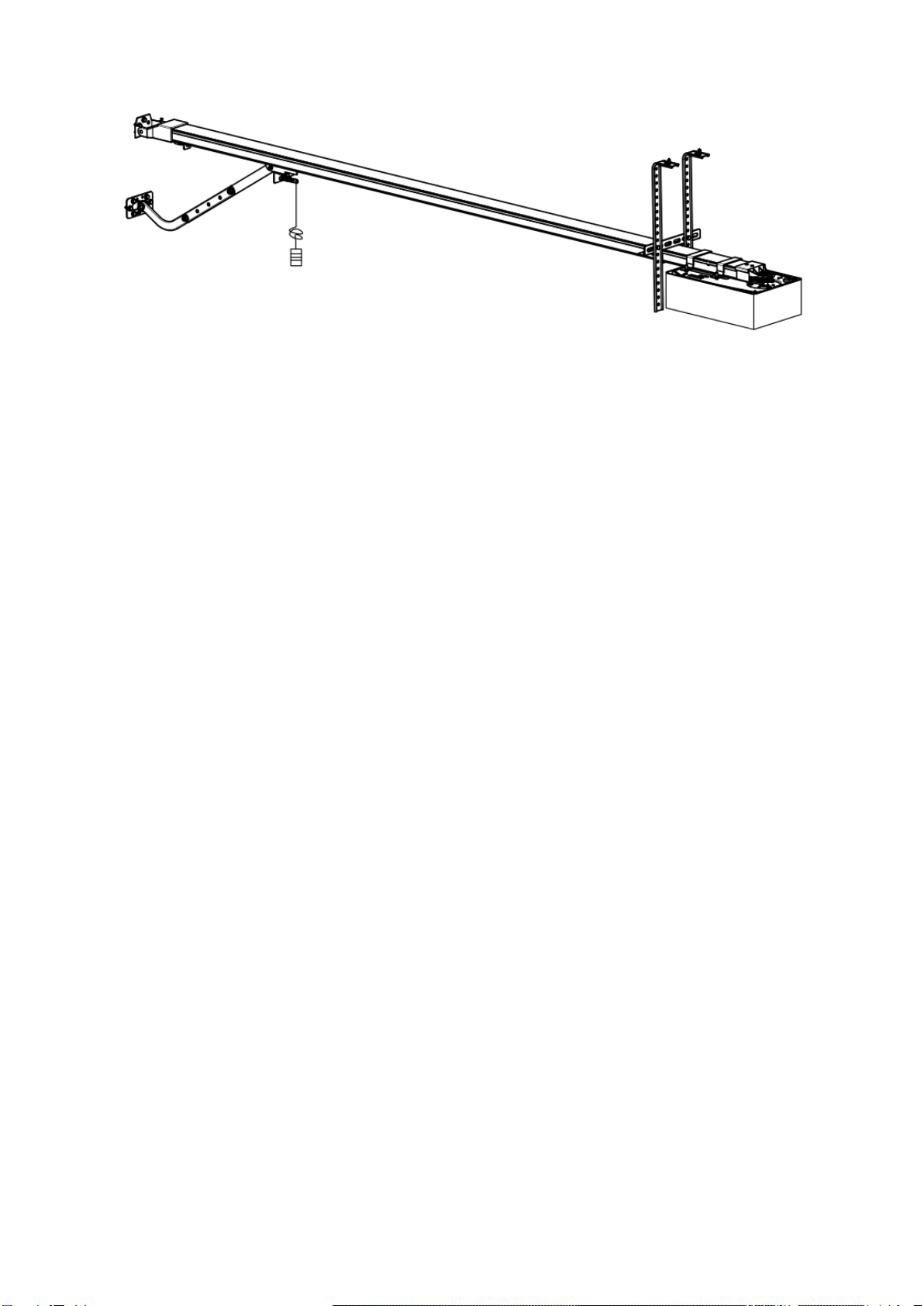
The device is not meant for commercial use but solely for the use in private garage doors that are
appropriate for a single household. The device is installed indoor and max 2,5m away the door, and
min 0,5m away the ceiling of garage. Check the Installation instruction for details. Any improper use
of the drive could increase the risk of accidents.

- 3 -
Basic function introduction
1. Soft start, soft stop. Minimize start-up load on garage door opener and garage door
2. The door will stop during opening when contacting obstruction, and will reverse at least 30cm
during closing when contacting obstruction.
3. Opening & closing force dynamically self-learning. Can make sure the garage door driver will
work steadily in spite of change of door resistance by seasonal variation.
4. Safety resistance adjustable, with a wide range, sensitive and reliable.
5. Overloading force detecting, the door will reverse more than 15 cm automatically when it is
overloaded when closing and will stop when it is overloaded when opening.
6. Low-voltage protection, the process will not perform any action of opening and closing when
voltage is too low, door panel and controller won‟t be damaged.
7. We adopt rolling code transmitter, with billions of codes, won‟t be coincident code or pirated
code.
8. Auto-close function available.
9. Backup battery interface available, in case of power failure.
10. Wall switch interface available.
11. Photocell interface available, the door will change to open when obstruction is detected
while closing.
Special function introduction (optional)
The following functions are made to order in accordance with the special needs of
customers:
1. Flash light feature
2. Pass door protection feature
3. Remote lock function
4. Half-opening function

- 4 -
Installation
1). Read the instructions carefully.
2). Make sure the door structure is solid and suitable to
be motor driven.
3). Make sure that when the door is moving there are no
friction points.
4). The door must be properly balanced and must be
easily lowered and raised by hand.
5). Install a 230-240V,adequately protected 3-pin socket
near where the GDO is going to be installed.
G
Fig.1
Fig.2
Referring to Fig. 2 for recommended installation
1) Opener track 5) Opener
2) 24V DC flashing light (optional extra) 6) Power socket
3) Push button
4) Photo beam (RX/TX Type)

- 5 -
Wall bracket
Cotter pin
Maintain a minimum gap of 30mm from the top panel‟s maximum height (Fig. 3).
Make sure the track is horizontal and vertical to the shaft. Make sure the connection of hanging
bracket F and ceiling is firm enough (Fig. 4).
Warning: Make sure the opener is affixed to noggins in ceiling and not to plasterboard. Failure to
have a safe and secure fixing will lead to opener falling, and cause serious persons and /or property
damage.
Installation (aluminum track)
Fig.5
Track bracket
U bracket B
Iron angle A
Bent arm
Fig.3
Fig.4
Wall bracket
U bracket A
Door bracket
Straight arm
Motor shaft adapter

- 6 -
Fig.6
Installation procedure
1. Fixing the wall bracket. Fixing the wall bracket to the wall 2cm-15cm over the shaft or
intermediate bracket (depend on the actual installation space).
2. Fixing the steel track to the wall bracket with cotter pin.
3. Sleeve the motor shaft adapter to the motor shaft according to Fig. 5.
Notice: the flanged end facing down.
4. Fixing garage door opener to the track by U bracket A . It‟s enough for 2 Nm fastening force.
5. Fixing the track bracket with U bracket B. Fix the track bracket as closer to the opener as you
can, if there is enough space.
Notice: Make sure the track is horizontal and vertical to the shaft.
6. Fixing the iron angle A to track bracket, hanging the track to ceiling by iron angle A. Make sure
the connection of iron angle A and ceiling is firm enough.
7. Fixing the door bracket on the door panel, fixing the straight arm and bent arm, fixing the clutch
cord.
8. Release the clutch, try to open and close the door by hand. Make sure there is no resistance
between door panel and track.
9. Connecting the opener with power and adjusting the operation.
Notice: Make sure the opener‟s voltage is in accordance with the local voltage. Connect the
opener to a properly earthed power supply.

- 7 -
Installation (one-piece steel track)
Fig. 7
Fig. 8
U bracket A
Iron angle A
Cotter pin
Track bracket
Wall bracket
Door bracket
Straight arm
Bent arm
Motor shaft adapter

- 8 -
Installation procedure
1. Fixing the wall bracket. Fixing the wall bracket to the wall 2cm-15cm over the shaft or intermediate
bracket (depend on the actual installation space).
2. Fixing the steel track to the wall bracket with cotter pin.
If the track is with belt, then go for step 3, if track is with chain, then skip to step 4
3. Sleeve the motor shaft adapter to the motor shaft according to Fig. 6
Notice: the flanged end facing down.
4. Fixing garage door opener to the track by U bracket A . It‟s enough for 2 Nm fastening force.
5. Fixing the track bracket to the track. Fix the track bracket as closer to the opener as you can, if
there is enough space.
Notice: Make sure the track is horizontal and vertical to the shaft.
6. Fixing the iron angle Ato track bracket, hanging the track to ceiling by iron angle A. Make sure the
connection of iron angle A and ceiling is firm enough.
7. Fixing the door bracket on the door panel, fixing the straight arm and bent arm, fixing the clutch
cord.
8. Release the clutch, try to open and close the door by hand. Make sure there is no resistance
between door panel and track.
9. Connecting the opener with power and adjusting the operation.
Notice: Make sure the opener‟s voltage is in accordance with the local voltage. Connect the opener
to a properly earthed power supply.

- 9 -
Installation (sectional steel track)
1. Cut the plastic cable tie on the first piece track
2. Fix the first sleeve to the first piece track
3. Fix the second piece track to another end of first sleeve
4. Repeat above steps to fix the second sleeve, third piece track
5. Pull the rod along the track towards another end
6. Fix rod according to below picture
7. Install according Fig. 7
Fig.9
Fig.10
Fig.11
Fig.12
Fig.13
Fig.14

- 10 -
Installation recommendations
Remember there are specific standards that have to be strictly followed regarding the safety rules of
electrical installations and automatic gates and doors.
As for the legal requirements and standards that must be adhered to, please take notice of the
following points to ensure maximum safety and reliability of your installation.
1. Before installing checking the surrounding environment. Carefully evaluate any hazards which
could be physical damage (transiting vehicles, parts of trees falling etc.), possible contact with
persons‟ bodies (insects, leaves, etc.), flooding hazards, or any others exceptional events.
2. Check the main voltage numbers is the same as the numbers that are given on the rating plate
and in this manual.
3. Check and make sure if there is suitable electrical protection against short circuits/power spikes
and proper earthing on the main supply.
Remember the unit having main voltage running through it (electrocution hazard, fire hazard).
4. Take care with the control unit; the parts may be subject to damage if the control unit is abused.
5. Make sure that you have all the necessary materials, and they are suitable for this kind of use.
6. Read all the instructions thoroughly, and make sure they are understood before attempting to
install the opener.
7. Before starting the installation carefully analyze all the risks relating to automating the door. Verify
that the door is automated in a sound condition and that the mechanisms are in good working order.
Observe the safety margins and minimum distances.
8. Carefully evaluate the safety devices to be installed and the right place to install them; always install
an emergency stop device for power interruption to the opener if it is required.
9. Once the risks have been analyzed, install the opener and relative safety devices, emergency
stop and/or photoelectric cells.
Important note: As for additional safety rules, we strongly recommends the fitting of Photo Electric
safety beams on all installations.
10. While installing the opener, strictly follow all the instructions given in the instruction manual. If
some points or procedures in this manual are not very clear do not install the unit until all doubts
have been cleared up with our technical department.

- 11 -
Basic function setting
1. Limit setting Opening & closing force dynamically self-learning
2. Matching the receiver and transmitter
Fig. A
Fig. B
Press „SET‟ button and hold on until the LED displays
figure „1‟, then adjust the up limit by pressing „up‟ button.
Fine-tuning „UP‟ or „DOWN‟ button to determine the final
up limit position then press „SET‟ button the display turn
into „2‟ automatically. Adjust the down limit by pressing
„down‟ button. Fine-tuning „UP‟ or „down‟ button to
determine the final down limit position then press „SET‟
button. The opener will operate a cycle automatically to
remember the limit positions and the opening & closing
force.
Press „CODE‟ button and hold on until the LED dot
flashes. (Fig.A) Then press any button on the transmitter,
the dot will be off; press the button again the dot will fast
flash then LED displays „u‟(Fig.B). After that the
transmitter will be available. It will be able to control the
open, close, stop of the garage door driver.
Press „CODE‟ button more than 8 seconds (the LED dot
flashes) until the LED displays „C‟, all the stored codes
will be deleted.

- 12 -
3. Safety reverse force adjustment
4. Auto-close setting
5.Photo beam setting
6. O/S/C Terminal
Press „SET‟ button and hold on until the LED displays
„3‟. It‟s under force adjustment mode. LED shows the
current force level.
Press „UP‟ button to increase the force level and
„DOWN‟ button to decrease the force level.
Version 1: Maximum force level is 9, minimum is 1.
Please make sure the photo beam is connected and can
work properly before you choose level 4~9.
Version 2: Maximum force level is 3, minimum is 1.
Press „SET‟ button to confirm.
Press „UP‟ button and hold on, the LED will display the
current setting (the factory default setting is „0‟).
Press „up‟ button once, the auto-close time will increase 1
level, the maximum is level 9. Press „down‟ button once,
the auto-close time will decrease 1 level.
The auto-close function will be turned off when LED
displays 0.
Version 1: 1 level = 60seconds
Version 2: 1 level = 15seconds
Press „SET‟ button to confirm. When the auto-close
function is activated, the full opened door will auto-close
after the set time.
Press „DOWN‟ button and hold on until the LED displays
„||‟.
Press „UP‟ button the LED displays „H‟, photo beam
function is available.
Press „DOWN‟ button the LED displays „||‟ to cancel this
function.
Press „SET‟ to confirm.
Make sure that the connected infrared sensor is controlled
by switching value, and wiring as Fig. 15
Notice: If photo beam function is activated, while the
photo beam is not connected, the door will not close.
Connecting a touch off switch to this terminal (Fig. 16),
you can use the switch inside the garage to control the
open/stop/close of the door when maintaining or the
transmitter is lost.

- 13 -
Special function introduction (optional)
The following functions are made to order in accordance with the special needs of
customers:
1. Flash light function
There are corresponding interfaces for this function and provide 24v-35v flash light
voltage. Connect the flash light with DC 24v-28v, current ≤500mA(Fig.18). When use AC
230-240V power flash lights, please match an adapter, and wiring as required (Fig.19).
2. Pass door (SD) protection
This function ensures that the door can‟t be opened unless the small pass door is closed.
The door panel won‟t be damaged. Connect according to Fig.17.
3. Remote lock function
4. Partial opening function
Press and hold on „SET‟ button until the LED displays „4‟.
It‟s in remote lock function setting mode.
Press „UP‟ button, the LED displays „1‟, the transmitter
lock function is available. Press „DOWN‟ button the LED
displays „0‟, the lock function has been turned off.
Press „SET‟ to confirm.
You have to press lock button on remote a few seconds
later after the door was fully closed, then you can open the
door again by remote.
Press and hold on „SET‟button until the LED displays figure
„5‟. It‟s in partial opening function setting mode.
Press „UP‟or „DOWN‟ button, the LED will display figure „0‟
to „9‟automatically.
When LED displays ‟0‟, the partial opening function is
invalid;
When displays „1‟, the door will stop at 30cm above ground;
When displays „2‟, the door will stop at 60cm above ground,
and so forth.
When LED displays ‟9‟, the door will stop at 270cm above
ground.
The function defaults to invalid when the stated range is
over than the door‟s limited opening range.
Press „SET‟button again to confirm.
Lock button
Lock button
Lock button
Partial
opening
Partial
opening
Partial
opening

- 14 -
Wiring guide
Fig.15
Fig. 16 Fig. 17
Fig. 19
Fig. 18

- 15 -
Manual disengagement
The opener is equipped with a manual release cord to disengage shuttle and move door by hand
while holding the handle down (Fig 19). Pull on the handle to disengage the shuttle. To re-engage
the door simply run opener in automatic mode or move door by hand until the trolley engages in the
chain shuttle.
In some situations that a pedestrian door is not in state, it is recommended that an external
disengagement device should be fitted (Fig 20).
Fig. 19 Fig. 20
Maintenance
No particular maintenance is required for the logic circuit board.
Check the door at least twice a year if it is properly balanced, and all working parts are in good
working condition or not.
Check the reversing sensitivity at least twice a year, and adjust if it is necessary.
Make sure that the safety devices are working effectively (photo beams, etc.)
Notice: A rude operating door can affect the life of the automatic opener due to incorrect loads,
and will void the warranty.

- 16 -
Manufacturer’s Declaration
We hereby declare that the product of this model corresponds in its design, construction and version
to the relevant and basic health and safety requirements of the following EC regulations: EMC
Directive and Low Voltage Directive. The detailed standards are as follows:
EN 55014-1, EN 55014-2, EN 61000-3-2, EN 61000-3-3
EN 301 489-1, EN 301 489-3
EN 60335-1, EN 60335-2-95, EN 62233
Final notes
This manual is only used by technical persons who are qualified to carry out the installation.
No given information in this manual can be considered of any interest to the end user.
It is important for the installer to show their clients correct operation using of the opener including
the using of manual disengagement cord.
Inform the owner about the need of a regular and accurate maintenance, especially regarding a
regular check of the safety and reversing devices.
Technical specifications
Model
600N
800N
1000N
1200N
1500M
Power Input
200W
235W
245W
260W
300W
Max force
600N
800N
1000N
1200N
1500N
Door opening
size
10m2,
100kgs
12m2,
120kgs
14m2,
140kgs
16m2,
160kgs
18m2
180kgs
Input Voltage
230-240VAC 50/60Hz
(subject to customer‟s area)
Light time
3 minutes
Working
temperature
-20°~ 40°C
Relative
Humidity
<90%
Radio
frequency
433.92MHz or other on request
Decoding
Rolling code
Transmitter
power
12V Battery
Lamp
Chip LED

- 17 -
Standard packing list
Item
Quantity
Door opener
1
Track ( incl. Clutch)
1
Remote control
2
Door bracket
1
Wall bracket
1
“U” bracket A
2
“U” bracket B (If aluminum track)
1
Iron angle A
2
Track bracket
1
Clutch cord
1
Cord pendant
1
Straight arm
1
Bent arm
1
Fixing kit
1
General Error Code
Code
Failure
Possible causes
Proposed solutions
E1
No signal
detected on main
hall sensor
Main hall sensor loose
Check & fix connection between
main hall sensor and PCBA.
E2
No signal
detected on sub
hall sensor
Sub hall sensor loose
-Check & fix connection between
sub hall sensor and PCBA.
-Power off and restart the device
E3
Sub hall count
faster than main
hall
Main hall sensor and
sub hall sensor wire
switched
Swap main hall sensor and sub hall
sensor wire on PCBA, learn travel
limit again.
E4
Wicket door
terminal open
circuit
-Wicket door is open
-Wicket door
connecting wire is loose
-Wicket door terminals
are loose
-Close the wicket door
-Fasten the wicket door connecting
wire
-Fasten the wicket door terminals
E5
Motor not work
-Incorrect type motor is
used
-Motor is damaged
-Replace with a correct type motor
-Replace with a new motor
E6
Door blocked
during closing
-There's object under
the door
-Stuck between door
track and door
-Move away object under the door
-Adjust door installation & reset
travel limit

- 18 -
1.0.0.220105
Table of contents
Popular Garage Door Opener manuals by other brands

Chamberlain
Chamberlain A1633M Additional instruction manual

Chamberlain
Chamberlain Merlin MS65MYQ Installation and operating instructions

Craftsman
Craftsman 139.53974SRT owner's manual

fadini
fadini MEC 200 LB instruction manual

FAAC
FAAC 740 manual

Automatic Technology
Automatic Technology GDO-6v4 EasyRoller installation instructions

DoorHan
DoorHan YETT 01 Installation and operating instructions

Chamberlain
Chamberlain CSW200UL8 manual

Nice
Nice AVIO500 Instructions and warnings for installation and use

Chamberlain
Chamberlain Merlin Professional MR800 Installation and operating instructions

Craftsman
Craftsman 315 SERIES 139.53939D owner's manual

Chamberlain
Chamberlain HD175D 1/2 HP manual