Horton 2000 Series Manual

H201C, OCTOBER 2005 A U T O M A T I C S
1.0011d
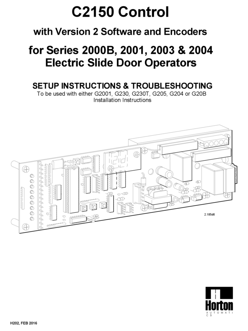
C2150 CRM Control
with Version 1.41 Software and REED Switches
for Series 2000 Clean Room
Electric Slide Door Operators
SETUP INSTRUCTIONS & TROUBLESHOOTING
To be used with G200 Installation Instructions

CONTENTS
SECTIONS
1. Series 2000 slide operator quick start instructions………………….. H201C.1
2. C2150 initialization……………………………………………………… H201C.2
3. Adjusting parameters (Procedure for changing preset parameters).. H201C.3
4. Adjustable preset parameters (chart of adjustable ranges)…………. H201C.3
5. Actuation features………………………………………………………… H201C.4
6. Autolock set up and initialization……………………………………….. H201C.4
7. Setting lock parameters…………………………………………………. H201C.5
8. Lock error codes (Trouble shooting guide)…………………………… H201C.5
9. Autolock test points……………………………………………………… H201C.5
10. Autolock functions……………………………………………………….. H201C.5
11. Reed switch diagnostics………………………………………………… H201C6
WIRING DIAGRAMS
1. C2150 typical wiring for 2000 linear drive………………………………. H201C.7
2. Actuating and control switch connections………………………………. H201C.8
APPENDIX
A. In case of difficulty (Trouble shooting the C2150)…………………….. H201C.9
B1. Code displays (definitions and trouble shooting guide)…………….. H201C.10
B2. Code displays (definitions and trouble shooting guide)…………….. H201C.11
B3. Code displays (definitions and trouble shooting guide - short cuts).. H201C.12
C. Terminal CN2 (Description of terminal block connections) …………. H201C.13
D. Motor test………………………………………………………………….. H201C.13
GENERAL STATEMENT
The C2150 is a microprocessor that uses a series of inputs, outputs and custom software to control a slide door.
The inputs are usually supported by LEDs that lets the technician see what information is coming into the control
and the outputs are in the form of display codes, LEDs and actual control of the motor, autolocks etc. This manual
is written for the C2150 control with Version 1 software which is used in the controls of the 2000 series linear drive
operators. The C2150 control receives its power from a separate power supply (usually a C3955) which
provides +27 to +35 VDC to power all of the accessory devices as well as power for the control itself. The power
supply also delivers +100 to +120 VDC to the control which is reduced by a MOSFET (duty cycle control) and is
called into service at variable levels through software and parameter selection. It is our hope that this manual will
guide the experienced technician through the efficient and safe setup of the C2150 slide door control. Remember
that all installations must comply with ANSI 156.10.

The E6040 must be plugged
into CN11 on the control
using the C2023 harness
3rd Step
Set the reversing sensitivity
fully counter-clockwise.
POWER SUPPLY
C3955 for 120VAC
To AutoLock
CN 7
If the day / night mode is NOT
to be used - there MUST be a
jumper between 15 & 16.
See Sections 5 thru 10 for actuating
features and lock set-up.
NOTE:
Do NOT wire any motion detectors or
any other accessories at this time.
Factory pre-wired beams (pins 5,6 & 7) may
be left in place.
1.0009d
11-08
2nd Step
16
15 Plug into E6040
Wht
Orn
Blk
Brn
Blu
Red
CN 4
1. SERIES 2000 SLIDE OPERATOR QUICK START INSTRUCTIONS
9th Step
Verify jumpers JB1A & JB1B
ARE REMOVED on rev. E and
later controls.
To get the operator up and running, check the items outlined below-
C2150 Control with version 1software (Revision E or later hardware)
A toggle switch or jumper must
be present between pins 8 & 9.
Switches are sent loose and field
mounted. Break-outs are wired in
series with the toggle switch.
9
8
2000
switch
Optional
switch
CN 2
1st Step 8th Step
The motor must
be plugged into
connector CN8 6th Step
H201C.1
Ground GRN U.S. - GRN / YEL Int.
(Connect to grounding screw)
Check that the incoming power is
wired as shown.
Line (Hot side) BLK U.S. - BRN Int.
Neutral WHT U.S. - BLU Int.
F 3
Motor
+100 to +120
VDC
1
F 2
F2F3
To REED
switches
See pg
H201C.6
CN 2
Grn
Yel 2
3
All fuses are
5x20 mm Type "T"
Rated 3.15 amp
+27 to +35VDC
& processor
F 1 Master
fuse
AC POWER IN
CN 1
A 5 conductor cable attaches CN7
to the power supply.
6th Step
BLK
RED
4th Step
CN 8
TO MOTOR
1 2 3 4 5GND
7th Step
Check incoming voltages
from power supply
+120 to +100
VDC from F2 +27 to + 35
VDC from F3

-A full learn cycle can not be completed with this security parameter in place.
Consult your supervisor or the factory for authorization and instructions on how to remove
this security parameter.
In version 1.17 and later, the display will show SU
-If SU does not appear, then the control was not
properly reset into the full learn mode (Go back
to step 2)
-If the display flashes nA like an error code,
The nA (no Access) parameter has been
turned on.
-The control will display ONE of the following
lock codes depending the type of lock
connected. (see Section 6)
-The display should "blink" the version number
(as in 1 then 17)
When the toggle switch is on, the DOWN button acts as an actuation device.
The door will move - Be sure the safety beam area is clear of obstructions.
Activation devices should not yet be installed.
4th Step -Checking door cycle
10/05
1.0013d
*LOCK CODES
Y
Fail Safe
Autolock
R
+100
OR LOCK
O
Y
LOCK
MON
No
Autolock
OR
+100
+100
R
R
R
+100
+100
R
LOCK
MON
Fail Secure
Autolock
O
LOCK
LOCK
MON
O
LOCK
Y
THEN
O
Y
Y
O
LOCK
LOCK
MON
Y
LOCK
MON +100
R
LOCK
LOCK
MON
LOCK
O
2. C2150 INITIALIZATION
Instruct the control to perform a full learn cycle by:
-Holding down the SET button and the RESET button.
-Release the RESET button.
-Hold the SET button for an additional 5 seconds
then release.
Be sure the toggle circuit is completed and apply
AC power to the unit.
CAUTION: THE DOOR WILL MOVE.
VERSION 1.00 and earlier
The display should "blink" the version number
(as in 1 then 00) *The display will showthe lock
code (see below)
2nd Step - Learn cycle
3rdStep-Versiondisplay
VERSION 1.17 and LATER
1st Step - Power up
SET
R
+100
R
+100
O
LOCKLOCK R
O
O
LOCK
MON
LOCK
MON
THEN
LOCK
MON
LOCK
Y
Y
+100
Y
RESET
H201C.2
-If the above cycle check is OK and there are no parameters to be changed or an
autolock to setup, this concludes the C2150 initialization.
Ver 1.17 or later
IF THERE IS ANY DIFFICULITY SEE APPENDIX A
The closing speed should not exceed the rate of 1 ft / sec
ROR
-The display returns to:
Ver 1.00 to 1.16
+100
-Close Check
-Close cUshion
-Time Delay
-Close Speed
Close Cycle
R
+100
+100
R
R
+100
+100
R
+100
R
Inspect the unit for smooth operation, free of binds and excessive noise.
OR
Start with the door in the closed position.
Press the DOWN button to actuate the door to open at factory selected
default settings.
The chart below shows the position of the door and the display code for each position.
-The display starts with:
*Braking may overide open check display
-Open cUshion
-Open Check *
-Open Speed
-Motor Braking
Open Cycle Ver 1.00 to 1.16
The follow cycles are
carried out automatically
by the C2150 control R
+100
+100
R
+100
R
+100
R
R
+100
Ver 1.17 or later
UP
+100
R
DOWN SET

-The display will show the current value or setting of
the parameter.
-Set the reversing sensitivity as required using R10. Do not
leave this adjustment at minimum. Horton recommends setting
the sensitivity so the door will reverse at 28 ft.lb. or less.
-When all adjustments have been made and checked, be
sure the toggle circuit is on.
10th Step -Saving new settings
-While holding the SET button,
press the UP or DOWN button to modify the setting.
-With the display reading 2d or da press and HOLD the
SET button until dS (data save) is displayed. All of the
changes are now stored in the control's memory.
This step must be performed or the control will revert to
the default settings after a power failure.
-When the SET button is released, the display will show
the parameter that was just changed. Another parameter
may be changed, or the toggle circuit turned on to check the
changes just made. In versions 1.10 and up the SET button
may be double clicked to exit the menu (toggle must be on).
1.0014d
10/05
+100
R
SET
UP DOWN
SET
DOWN
R
+100
UP
R
+100
-When the parameter to be changed is found, press
and hold the SET button.
-The display will switch to the menu of adjustable parameters
-In versions 1.08 and up, the right decimal point will be blinking
-Turn the toggle switch OFF
Or for versions 1.10 and up, leave the toggle ON and
double click the SET button.
A chart of preset values is shown to the right.
If any speeds or other settings need to be changed, follow this procedure:
9th Step - Changing parameter settings
3. ADJUSTING PARAMETERS
-Scroll through the parameter list using the UP and
DOWN buttons until the parameter to be changed is
found.
-Refer to the chart in section 4 for a list of codes for
adjustable parameters. UP DOWN SET
R
+100
UP DOWN SET
R
+100
UP SET
DOWN
H201C.3
on (version 1.12 & up only)
oF (lock stays unlocked in day mode)
oF (version 1.02 & up only)
oF(fail-secure) (on fail-safe)
oF (monitored lock)
oF (on if Horton lock is present)
oF (on)(Version1.02 & up only)
oF (version 1.16 & up only)
oF (version 1.17 & up only)
oF (version 1.04 and up only)
oF (version 1.17 & up only)
**In versions 1.07 & prior, d1 and d2 adjust from 1-199 seconds.
**Beginning with version 1.08, these parameters may be set to 1-8, 10, 12,14, 16, 20, 25,
30 or 60 seconds.
! Prior to 1.17, sidelite protection device was wired to 10 & 11 of CN2. 1.17 and later
is wired to 6 &7.
-A double dash (--) is a reserved parameter that is not implemented.
*Caution: very light doors may require a lower speed setting
Lock present
brake on recycles
fail-SAfe lock
Close braking
no Adjustment permitted
Power fail Night mode
Apex Enable
Longer Timeouts
Sidelite Protection
daytime Lock
daytime 1-way Lock
Unmonitored Lock
!
oF/on
oF/on
oF/on
oF/on
oF/on
oF/on
oF/on
oF/on
oF/on
oF/on
oF/on
oF/on
3
4
4
10
3 (factory set - do not change)
1 (factory set - do not change)
1 sec
1 sec
3
12*
FACTORY PRESET VALUE
20
The chart below shows all the adjustable parameters for version 1 software.
Follow the procedure outlined in step 9 to make any necessary changes.
3 (factory set - do not change)
oF (no)
OP (power fail OPen)
oF (no)
oF (no)
4.ADJUSTABLE PRESET PARAMETERS
delay time 2 (partial open)
delay time 1 (full open)
Close cUshion
Open cUshion
Power Fail
Heavy-duty door/motor
cycle test
Auto Seal
brake time
CloseCheck
Close Speed
Open Speed
PARAMETER
Open Check
CODE
0-100
oF/on
OP/CL
oF/on
oF/on
0-15
1-60**
0-15
1-60**
0-15
0-15
ADJUSTS
0-15
0-15

Auto lock circuit board
Connect to CN 4
Remains locked at power failure
FAIL SECURE
Double click = off or on
Press and hold = data save
13
Many other features, for autolock and motion
detector configuration, are available through
additional adjustable parameters.
These parameters can be discussed in
greater detail by calling the technical
service group.
1.0012d
10/05
NOTE:
2-way night mode
setting is:
NO jumpers or
switches
1-way night mode
setting is:
jumper or switch from
13 to15
NO jumper or switch from
15 to 16
15
16
15
13
TS 1
Security panel
connections
(optional)
4 WHT
3 GRN
CN 1
1 BRN
2 RED
5 BLK
1 2 3
5. ACTUATION FEATURES CODE
DISPLAY
2-way day mode
factory setting is:
jumper or switch from
15 to16.
1-way day mode
setting is:
jumper or switch
from 13 to15
and 15 to 16.
16
Com 15
13
16
15
Set jumpers or key
switch for the type of
operation required.
See diagram 2
page H201.9
D1
RESET
1
CN 4
These displays
apply to 1.17 and
up only
UP DOWN
Display Scroll
LOCK
MON
(Yellow)
(Orange)
LOCK
H201C.4
If there is no response it
knows there is no lock.
The C2150 looks to see if there is a contact at the
lock port CN4 and if the yellow lock monitor LED
is on.
The control sends a pulse
to retract solenoid...
FAIL SAFE
If the yellow LED is on...
LOCK
MON
LOCK
Security panel
switch (optional)
Lock monitor
switch
Coil test
points
Unlocks at power failure
FAIL SAFE
O
Y
LOCK
MON
If the control gets a
response back, it
knows there is a
fail safe lock.
R
+100
SOLENOID
LOCK
O
Y
LOCK
MON
Y
+100
RLOCK
O
If there is no response it
knows there is no lock.
The C2150 looks to see if there is a contact at the
lock port CN4 and if the yellow lock monitor LED
is off.
The control sends a pulse
to retract the solenoid...
FAIL SECURE
6. AUTOLOCK SET UP AND INITIALIZATION
Press SET and RESET simultaneously, release
RESET, wait 5 seconds,then release SET - version
number will displayed.
During initialization the control clears all ports and
the solenoid becomes inactive.
If the yellow LED is off...
Y
LOCK
MON
LOCK
O
SET
If the control gets a
response back, it
knows there is a fail
secure lock.
SOLENOID
R
+100
R
+100
Y
LOCK
MON
O
LOCK
O
LOCK
Y
LOCK
MON

CN 1
Basic voltage readings regardless of type.Set VOM at 200VDC.
NOTE: The terminal strips TS1 & TS2
are located on the autolock
UnLock Failure (Fail Safe ) Indicates that the lock solenoid spring has failed
to move the plunger enough to activate the lock monitor switch and notify the control that
the door is ready to be opened.
Lock Failure (Fail Safe ) Indicates that the lock solenoid failed to move
the plunger enough to activate switch on the lock monitor.
Check for mechanical binding. Check items under AUTOLOCK TEST POINTS and
AUTOLOCK FUNCTIONS FOR FAIL SAFE autolocks.
9. AUTOLOCK TEST POINTS
-When the control's orange lock light is on there
should be 3 to 5 VDC between pins 2 and 5 at TS 1.
-There should always be a supply voltage of
25 to 33 VDC between pins 1 and 5 at TS 1.
2
CN 1
GRN
3
WHT
BLK
WHT
BLK
GRN
RED
BRN
CN 1
3
4
5
1
2
5
4
1.0015d
10/05
LOCK
MON
Y
LOCK
O
BRN
RED
1
SEE SECTION 3 STEP 10 FOR ( ds ) DATASAVE PROCEDURE
UnLock Failure (Fail Secure ) Indicates that the lock solenoid failed to move
the plunger enough to activate the lock monitor switch and notify the control
that the door is ready to be opened.
Lock Failure (Fail Secure ) Indicates that the lock monitor input is remaining
active (lock monitor light is still on) even though solonoid has de-energized.
Check for mechanical binding. Check items under AUTOLOCK TEST POINTS and
AUTOLOCK FUNCTIONS FOR FAIL SECURE autolocks.
To set up the lock parameters on the C2150 turn off the toggle circuit or double click the
SET button. Use the UP / DOWN buttons to locate dL & L1.
Press the set button to display the on or off setting. Set dL / L1 as required from the table
below.
UnlockedUnlocked
Locked
Locked
Locked
7. SETTING LOCK PARAMETERS
Unlocked
Day 2-Way
8. LOCK ERROR CODES
2-Way
1-Way
1-Way
Day
Nite
Nite Unlocked
Locked
Locked
SEE STEP 1 FOR SET UPSEE STEP 1 FOR SET UP
Traffic Mode
Locked
Locked
Locked
Locked
doesn't
matter
The yellow lock monitor
and the orange lock LED's
should both be lit when the
solenoid is retracted.
O
H201C.5
When the lock is unplugged and
the solenoid manualy depressed
there should be continuity between
pins 4 and 5 of TS1
RED
2LOCK
MON
The FAIL SAFE isalesscommontypeofautolockusedwiththeC2150.
When power is applied the solenoid
is extended and the door is locked.
When the lock is unplugged and the solenoid is not manualy depressed
there should be continuity between pins 4 and 5 of TS1
Keeper
O
LOCK
LOCK
MON
Y
When power is removed the solenoid
is retracted by the lock spring. The
door is unlocked.
The yellow lock monitor
LED is lit when the solenoid is
not retracted.
LOCK
Y
O
LOCK
MON
SOLENOID
Lock spring
BLK
GRN
WHT
4
3
5
The orange lock LED is lit
when the solenoid is retracted.
Lock spring
Y
SOLENOID
The FAIL SECURE is the most common type of auto lock used with the C2150.
After about a second the voltage will drop
to about 30% of the supply voltage between pins
1 and 2 of TS2 .
-When the solenoid initially energizes there
should be 25 to 33 VDC at TS2.
10. AUTOLOCK FUNCTIONS
Keeper
Latch
bolt
BRN
1No LED's are lit
When power is removed, the solenoid
is extended by the lock spring. The
door is locked.
SOLENOID
Lock spring
Auto lock circuit board
COIL
When power is applied the solenoid
is retracted and the door is unlocked.
Lock spring
LOCK
SOLENOID

DOWN
+100
Wht
Blk
Orn
Close check
Wire
retainer
Open check
Blu
Open cutoff
Brn
Close cutoff
Orn Red
Wht
Brn
Grn
Yel
Blu
Blk Grn
Yel
Red
-Move the door manually through the open and closed positions to verify that each code is present for the position listed.(See the chart below)
-A blank display means that the door is in mid-stroke (no switches are tripped).
-Missing codes, or codes that appear in improper order, indicate a problem with a switch assembly or a defective switch lace, or possibly the C2150.
R
C2045
MAGNET
-Full OPen
-Open Check
Open Cycle
1.0010d
10/21/05
+100
R
+100
R
C2022
Harness
11. REED SWITCH DIAGNOSTICS
In software Version 1.00 or later, press the
RESET & the DOWN button, release the
RESET and hold the DOWN button until
the display shows ut
Running a Reed switch test
DOWN
UP
RESET
SET
C2045
Magnet MOTOR END
The display will, briefly,
show ut (for Reed switch test)
Power up the control while
holding the DOWN button.
OR...
UP
H201C.6
To exit the reed switch test press RESET
-Fully CLosed
Close Cycle
-Close Check
RESET
+100
R
R
+100
MOTOR END
C2045
MAGNET
SET
Secure all switch wiring
with wire retainers

AUTOLOCK CONNECTOR:
1-BROWN(+24VDC)
2 - RED (LOCK ENABLE)
3 - GREEN (NOT USED)
4 - WHITE (MONITOR SW)
5 - BLACK (COMMON)
SERIES 2000 SLIDE DOOR OPERATOR & C2150 CONTROL
POWER SUPPLY CONNECTOR:
1 - WHITE (+90VDC)
2 - BROWN (MOTOR COMMON)
3 - RED (+24VDC)
4 - BLACK (24V COMMON)
5 - GREEN (GROUND)
OPTIONAL AUTOMATIC LOCK: C2176-5 FAIL-SECURE /C2196-5 FAIL-SAFE
WHEN UNIT IS IN NORMAL OPERATION, THE DOWN PUSHBUTTON WILL
ACTUATE CONTROL. PRESS & HOLD THE UP PUSHBUTTON, THEN PRESS
THE DOWN PUSHBUTTON & RELEASE BOTH TO INITIATE SELF-CYCLE.
ON / OFF
TOGGLE
SWITCH
(NOT REQ'D
WHEN USING
C3725-1 KEYSW)
120VAC
1.0021d
10/26/05
CN
C
N
O
3.15A
24VAC
90VAC
3.15A
F2
F3
C384
2
C3955 / C3956 POWER SUPPLY
3.15A
F1
120VAC
POWER
INPUT
RC
EXTERIOR O
TO C2150
14 NIGHT SW
13 2WAY / 1WAY
16 DAY/NITE SW
15 COMMON
3
G
N
D
SW
KEY
15.
14
13 16
BLK
BLK
WHT
INTERIOR Y
R
G
Y
G
G
12 PART'L OPEN Y
1+24VDC
9COMMON
7COMMON
6 SAFTY BEAM
8 TOGGLE SW
3EXTERIORSW
2INTERIORSW.
5+24VDC
4COMMON
10 RESERVED
11 COMMON
SW
CLS
MOT
EXT
MOT
TOG
SAF
BEM
SW
SW
MON
A
INT
21 6
34. 11.
10
9.
8
7.
512
SW
B
13 DOWN
Also see page H201C.6 for
wire color arrangement
NL
IE
12
UN
15.
14
16
UP SET
µSW
1
+5
1
+24
LOK
ULK
MON
COM
1
ENC
LOCK GND
1
1
10
8
6
5
3
2
4.
7.
9.
12
11.
VER 1.XX
RESET
+100
LOCK
RO
MON
LOCK
Y
Close
cutoff
11296.2
26OCT05 RA
TO REINITIALIZE CONTROL PRESS SET & RESET SIMULTANEOUSLY,
RELEASE RESET, WAIT 5 SECONDS, THEN RELEASE SET; UNIT WILL
RESUME NORMAL OPERATION. ALL PREVIOUSLY STORED SETTINGS
WILL BE LOST, AND CONTROL WILL REVERT TO DEFAULT SETTINGS.
TO READJUST, TURN OFF TOGGLE SWITCH, USE UP / DOWN BUTTONS
TO FIND PARAMETER; PRESS SET TO DISPLAY CURRENT SETTING.
PRESS & HOLD SET & USE UP / DOWN TO CHANGE SETTING.
RELEASE SET BUTTON. TO PERMANENTLY STORE, TURN TOGGLE
SWITCH "ON", PRESS AND HOLD SET UNTIL DS IS DISPLAYED.
Open
check
REED SWITCHES
See page H201C.6 for REED switch test
Open
cutoff
RedWhtGrn
Yel
Close
check
BluBrnOrnBlk
C4011 MOTOR
90VDC 1/8HP
1800RPM
MOTOR
K2K1
JU1
C215
0
HORTON
TO C3955 / C3956 POWER SUPPLY
REVERSING
SENSITIVITY
R10
K3
GND
5
1
2143
RED
BLK
H201C.7

GREEN (NOT USED)
YELLOW (SIGNAL)
WHITE (COMMON)
GRAY (COMMON)
GRAY (+24VDC)
Receiver - Blue Wire
Shield (9)
Wire (8)
Pair 2
Emitter - Gray Wire
Shield (11)
Wire (10)
Pair 1
C1234
SENSOR
(OPTEX 202C)
RED (+24VAC/VDC)
BLACK (COMMON)
WHITE (COMMON)
GREEN(ACTIVATION)
BROWN (COMMON)
BLUE (SAFTY BEAM)
Optional C3725 KeySwitch Assembly
/ C3726 Rotary Switch Assembly
Emitter - Gray Wire
Shield (13)
Wire (12)
Pair 2 6891071311 12
E
R
Receiver - Blue Wire
Shield (7)
Wire (6)
Pair 1
Power Harness
BLK (1)
WHT (2)
GRN (4)
RED (5)
RED = 2
GREEN = 1
4
OS-10C
112
BLUE WIRE
GRAY WIRE
R
E
EmitterReceiver
AC,DC, 12-24V
OPTEX
POWER
1
1
67 11
(Gray)(Blue)
22
13
N.C. N.O.
1
OUTPUT
3245
Power/Operation
Indicator
8 9 10 12
5
GRAY WIRE
BLUE WIRE
TEACH IN
FULL
OPEN
C7775
THRESHOLD
PHOTO BEAM SYSTEM
(OPTEX OS-10C)
Blue (1)
Gray (2)
4
3
5
2
1
8
7
6
Gray (1)
Blue (2)
1 / 2
OPEN
GREEN (NOT USED)
YELLOW (SIGNAL)
WHITE (COMMON)
GRAY (COMMON)
GRAY (+24VDC)
C1827
SENSOR
(BEA Wizard SMR)
1.148d6
01_07
WIDTH ADJUSTMENT NO. 7, 8
APPROACH AREA ADJUSTMENT
PRESENCE DETECTION
TIMER
FREQUENCY
SWITCH
L H 218060 (sec.)
SENSOR
78
~
18
8
~7
7
SENSOR
2
SENSOR
6
7
~
3NONE
SENSOR
88
7
C1238
SENSOR
(OPTEX i - one)
BLK
GRN
WHT
RED
DIAGRAM 2 ACTUATING and CONTROL SWITCH CONNECTIONS
GRN
RED
WHT
BLK
RED
1 2
1 2
HOLD OPEN
2 WAY AUTO
R
1
2
C
4
W
B
3
O
F
F
G
1 2 3 4
ON / OFF
TOGGLE
SWITCH
1
W
A
Y
WHT
BLK
GRN
RED
1 2 3 4
[See Lower Right for Sensors]
INTERIOR
ACTUATING
SENSOR
EXTERIOR
ACTUATING
SENSOR
+24VDC (BLK)
SIGNAL (GRN)
COM (WHT)
COM (WHT)
+24VDC (BLK)
SIGNAL (RED)
BLK
H201C.8
12 PART'L OPEN 12
Jumper15&16ifnoRemoteSwitchisused
13 14
12 15. 16
13 2WAY / 1WAY
15 COMMON
16 DAY/NITE SW
14 NIGHT SW O
RSW
KEY
C
SW
CLOSE
MONITOR
SWITCH
15.
16
14
13
11.
4. 6 7. 8
59.
10
123
5 +24VDC RMOT
10 CLS MON SW
11 COMMON
8 TOGGLE SW
6 SAFTY BEAM
9 COMMON
7 COMMON
G
YSW
B
Y
G
Y
TOG
CLS
SW
SAF
BEM
A
SW
MON
3 EXTERIOR SW
2 INTERIOR SW.
4 COMMON
1 +24VDC
GINT
EXT
MOT
5
10
11.
7.
6
9.
8
3
4.
2
1

CAUTION: disconnect the power supply at CN1 and wait 30 seconds before
servicing.
-Unplug the power harness at CN7 (section 1 step 8) and the motor at CN8 and
replace the fuse (slow blow 5 x 20mm Buss type GDC 3.15 or equal )
-If the fuse blows again, replace the power supply.
-If the fuse does not blow,reconnect the power harness at CN7 and attempt to
operate the door with the motor unplugged.
-If the fuse blows now, replace the C2150 control (first check motor as shown in
appendix C).
-If the fuse does not blow, plug the motor in and try again.
-If the fuse blows again and the motor checked good, check for a mechanical bind.
Check the br parameter in appendix A which can help prevent fuse blowing.
-Consult Technical Assistance at the Horton factory.
-Go to section 1 step 8 and check for DC voltages shown on CN7 terminals 1&2.
-If voltage is not present, check fuse F2 of the power swpply.
-If F2 is good power supply is faulty.
-If voltage is present on CN7 and display is showing a run code ie: 0S, 0U, [S,
[[ or [U check for motor voltage (with motor plugged in) on pins 1 and 2 of CN8
leaving the control. Use 200 VDC scale.
-If voltage is not present at CN8, change control.
-If voltage is present at CN8, go to appendix C for motor test.
H201C.9
1.0017d
10.DOOR FAILS TO GO TO EITHER OPEN OR CLOSE CHECK
See reedswitch test
See reedswitch test
9.DOOR WILL OPEN BUT NOT CLOSE
See reedswitch test
8.DOOR WILL CLOSE BUT NOT OPEN
APPENDIX A IN CASE OF DIFFICULTY
1.If DISPLAY FAILS TO LIGHT
2.If DISPLAY LIGHTS, BUT DOOR NEVER MOVES
3.DOOR SLAMS OPEN and / or CLOSED WITH NO SPEED CONTROL
4.DISPLAY WILL ONLY SHOW OS
-Make sure toggle circuit is complete by turning toggle switch off and on. The
green TSW LED should go off and come back on. This LED must be on for the
door to operate.
5.ERROR CODE OR SOME OTHER ABNORMAL DISPLAY APPEARS.
-Go to appendix B - find the code and follow the instructions.
6.FUSE F2 BLOWS REPEATEDLY
10/05
CAUTION: disconnect the power supply at CN1 and wait 30 seconds before
servicing.
-Unplug the power harness at CN7 (section 1 step 8) and all connections of pins
1 and 5 of CN2 and CN4 autolock, if present, and replace fuse F3 again
(slow blow 5 x 20mm Buss type GDC 3.15 or equal )
-If the fuse blows again, replace the power supply.
-If the fuse does not blow, reconnect the power harness to CN7.
-If the fuse blows now replace the C2150 control.
-If the fuse does not blow replace the autolock, and connections at pins 1 and 5
of CN2 one at a time until F3 blows indicating a short circuit in that component
or its wiring. Beams and their wiring are the most frequent cause of F3 failure.
7.FUSE F3 BLOWS REPEATEDLY
-Go to section 1 step 8 and check for DC voltages shown on CN7 terminals 3&4.
-If voltage is not present, check AC power at pins 1&2 of CN1 of power supply.
-If AC power is present, check fuses F1 & F3 of the power supply.
-Go to appendix C for motor test ( to make sure motor did not ruin control)
-If motor test good, change control.

D
VERSIONTYPE
E
D
D
D1.17
1.17
1.17
1.00
1.00
P1.02
1.00
P
P
P1.17
E1.17P
PD 1.16
D
P
P
1.00
1.16
1.16
P
P
1.00
1.00
1.00
D
PD
1.00
PD
PD
P
D1.09
1.00
1.17D
PD 1.00
D1.17
E
1.00PD
PD
1.00
1.00
1.00
1.15
1.16
D1.14
1.16DP 1.14D
D1.16
1.00
CODE
1.0016d
10/05
D1.17
D1.00
Door is idle in 1way day mode. See section 5
Door is idle in 1way night mode. See section 5
Door is idle in 2way day mode. See section 5
Door is idle in 2way night mode. See section 5
Use only with APEX system - see APEX instruction G550
bi stable Lock - no longer used
Power fail CLose see section14
Close Speed see section 2 step 8
APEX communication error - if using APEX then turn AP on
Close Check speed - see section 2, step 8
Use only with APEX system - see APEX instruction G550
P
H201C.10
1.02
This is a cycle code (see foot note ) from ext motec input see appendix D CN2
This is a cycle code (see foot note ) from DOWN button
Partial open delay is active when SW 'A' is on (App. D) & starts when all activate and recycle inputs have cleared & door is at partial open
APPENDIX B1 CODE DISPLAYS Codes are arranged in alphanumeric order (NOTE: D = Display, P = Parameter, E = Error)
This shows a successful Data Save. See section 3 step 10
Control failed to store parameters (control must be replaced)
DISPLAY MEANING
Door Locks (in day mode ) when this parameter is turned on. See section 7
Control has failed - must be replaced
To activate this APEX feature you must - turn the parameter on - do a data save, and then press reset only
This indicates battery failure of C3985 monitored power failure unit - see section 14
This parameter is factory set - do not change without consulting factory
Door idle in dAy mode.(Has been replaced in later software by1d or 2d parameter see section 5
Control is braking - door always brakes when opening. Close braking can be turned on at the parameter
When Auto Seal parameter is turned on, the display will change to AS and the control will try to close the door every 15 seconds
Determines how long control brakes motor after open speed
When close braking parameter is turned on, the control brakes the door after close speed - recommended for heavy doors
Use only with APEX system - see APEX instruction G550
This parameter determines stroke to open check. Adjustable from 50-90% of total stroke
Cycle test will cause door to open and close repeatedly for test purposes
Close Cushion speed (see section 2 step 8)
Main time delay- starts when all activate and recycle inputs clear and door is fully open
Use only with APEX system - see APEX instruction G550
Door was activated or is being held open by SW 'C' input. See App. D CN2 for wiring & LED
Brake on recycle turned on, the control will slow door substantially before reversing on recycle
Use only with APEX system - see APEX instruction G550

VERSION
1.16
1.16
1.16
P
P
P
P
D
TYPE
1.00
1.08
P1.17
1.14
1.16
1.16
E
1.16P
1.06
1.00
1.00
1.16
1.02
PD
D
D
P
P
P
P
P
E
P
1.00
1.04
PD
D
D
PD
D
1.17
PD
1.16
P
P1.12
1.17
PD
D
PD
P
1.00
1.09
1.00
1.00
1.00
1.00
1.00
1.17
1.17P
D
P
D1.00
1.17
CODE
10/05
1.0018d
1.17D
No Lock found during initialization (see section 6)
Provides Locking in 1way mode (see section 7)
APPENDIX B2 CODE DISPLAYS
H201C.11
Open Speed (see sect. 2 step 8)
This is a Power fail Open code (see sec.13)
Open Check speed (see sect.2 step 8)
Access restricted call factory for assistance
Indicates control is slowing for partial open
Door idle in night mode (Replaced in later versions by 1n & 2n) see sect. 2, step 8
Door has not reached close cut off switch. See sect. 1 step 2. Check for obstructions. See appendix A step 2
Open cUshion speed (see sect. 2 step 8)
This is a cycle code (see foot note) from Interior Motec see appendix D CN2
This parameter is factory set - do not change without consulting the factory
This parameter should be turned on when using a 1/4 HP motor and a light door. (Reduces abruptness of closing )
Shows lock is present (see sect. 6)
This is a cycle code (see foot note) from safety beam input.
Indicates fail SEcure lock is found during initialization (see sect. 6 )
This is a cycle code (see foot note) from reverser circuit.
This parameter is factory set - do not change without consulting factory
DISPLAY MEANING
When turned on triples time in open and close before t0 occurs
Displays at beginning of initialization (see sect 2, step3 in ver 1.17and up)
Indicates fail SAfe lock is found during initialization (see sect. 6 ) Parameter should be turned on if a fail safe lock is present.
Power Failure (see sect. 13)
Power failure (see sect. 13)
Use only with APEX system - see APEX instruction G550
Automatic Lock Failed to lock (see section 8)
Use only with APEX system - see APEX instruction G550
Provides Sidelite Protection when turned on. Reduces opening speed to open check when safety beam input is activated (see app D)
Use only with APEX system - see APEX instruction G550

-If an actuator is holding the door open, the updated software shows a "hold code"
instead of d1 or d2, to indicate which device is holding the door open, The displays shows
the various hold codes in sequence. When all devices are clear, the display will switch
to d1 or d2 and the normal time delay will start.
* These drawings are for a belt drive application and show a close monitor switch,
however, they may be useful to wire up beams and motion detectors.
DRAWING
No.
Use only with APEX system - see APEX instruction G550
Use only with APEX system - see APEX instruction G550 1.00
1.00
1.00
Use only with APEX system - see APEX instruction G550 1.00
SELF CYCLE MODE To initiate self cycle without accessing the ct parameter press and hold the UP
button then press the DOWN button and release them at the same time. If you haven't saved any
parameters, you can get out of this mode by pressing the RESET
button only. Otherwise you must go to the ct parameter and turn off and do a data save.
CYCLE DOOR Push the DOWN button. The door will open, and stay open until D1 expires and then
close.
LINEAR TRAVEL BLOCK ADJUSTMENT press and release RESET while holding UP &
DOWN simultaneously for five seconds. Motor will run in closed position to allow tension
to be set on the drive block.
X
C3881 w/ mag lock
11100.0 *
X
X
XX
11238.1 *
11229.0 *
11231.0 *
11247.0 *
CPSS12
11100.1 *
11101.1 *
11104.1 *
11105.0 *
APPENDIX C WIRING DIAGRAM LIST
11249.1 *
D
Autolock has failed to unlock (see sect 8)
This display indicates door did not reach the expected switch in time alloted
Brief display code at start of reedswitch test (see sect.11)
DISPLAY MEANING
ACTIVATE
C&K
C1188-1
VGO37
C1801
XXX
X
PARAMETER ACCESS (Version 1.10 and later) The menu may be accessed and parameters changed
by rapidly double clicking the SET button when the door is fully closed or opened. To exit double click
the SET button again and the control will return to normal mode. Turning the toggle off and on will
override this function.
RETURN TO THE TOP OF THE MENU(Version 1.08 and later) Press UP and DOWN together to
return to the top of the menu.
-While the door is at rest in the open position, pressing and holding the UP button will
switch the display to show the last cycle code; that is, the last device that cycled (or
recycled) the door. Releasing the UP button takes you right back to normal operation.
This is a kind of "mini-history" in case you didn't see the cycle code when the control
flashed it the first time.
X
X
Limited access
When this is turned on it tells the software not to wait for the lock monitor but try to open after a brief delay. Rarely used, only for non Horton locks
H201.12
BEAMS KEY SW AUTO-
LOCK
P
P
P
E
TYPE
SHORT CUTS
FOOT NOTES:
1.16
1.16
VGO87
C1802
C3725-L
4 POS
3976
PARTL
OPEN
X
X
X
X
-The latest versions, 1.14 and up, also have a new feature called cycle / hold codes.
Immediately after the door has opened to its stopping point (full or partial open), a
"cycle code" will flash briefly. This code indicates which device opened the door. The
cycle code is useful if a door is ghosting and you are trying to figure out which activating
device is causing the problem.
APPENDIX B3 CODE DISPLAYS
Security panel C1280
X
X
X
X
X
X
X
XX
10/05
1.0019d
1.16
VERSION
CODE
5 Position SW
P
D
X
4 BEAM
C1284
C&K
C1185
X
Exterior Actuator (pin 3 of CN 2)
Interior Actuator (pin 2 of CN 2) down button
Auxiliary Actuator (pin 14 of CN 2)
Safety beam (pin 6 of CN 2)
The cycle / hold codes used are:
ReVerser (cycle code only)

FRAME SHORT TEST
APPENDIX E MOTOR TEST
ADivision of Overhead Door Corporation, ASanwa Shutter Company
4242 Baldwin Boulevard
Corpus Christi,
Texas, U.S.A. 78405-3399
Tel: 800-531-3111, 361-888-5591
Fax: 800-531-3108, 361-888-6510
Internet: http://www.hortondoors.com
Form H201C, OCT 2005, printed in U.S.A.
Horton Automatics reserves the right to improve the product and change its specifications without notice.
Acceptable range
NOTE: A low reading is
critical and will cause
damage to the control.
RED (pin 2)
BLK (pin 1)
-NOTICE: a voltage will be induced into the
meter when the motor is moved, so wait for
the meter to stabilize before taking a reading.
A U T O M A T I C S
-Continue taking readings for 1 revolution
This test is conducted to determine the
resistance across the motor. A low
or zero resistance will cause high current
draw and damage to the control.
-Unplug the motor and place probes
in pins 1 and 2
-Read and record the resistance.
-Place OHM meter in range to measure :
10 to 50 ½ analog Rx1 range
R200 ½ digital.
-Rotate the motor a little bit to move to
the next section of the commutator.
(Feel for the brushes to make contact with the
next segment on the commutator.)
12 to
18 ½
BLK (pin 1)
Horton Automatics, Ltd.
Unit A, Hortonwood 31
Telford, Shropshire, England TF1-4GS
Tel: 01952 670169, Fax: 0192 670181
International Tel: ++44-1952-670169
International Fax: ++44-1952-670181
BLK (pin 1)
RED (pin 2)
RED (pin 2)
1.0020d
-Place one probe in pin 1(BLK) and one
probe on the motor case.
-Place one probe in pin 2(RED) and one
probe on the motor case.
-Place the OHM meter in the range to
measure at least 20,000 ½.
The meter should show infinite resistance
when connected .
The meter should not move
when the probes are connected.
½ = °
THEN...
D3 Y
D8 R
D2 R
D4 G
D7 Y
LED
H201.13
D1 G
D6 G
D9 O
D5 Y
A point behind a number
indicates common (ground)
This symbol indicates
24 volts DC
4.
NOTE:
CN 2
APPENDIX D TERMINAL CN2
Terminals
1 thru 15
LED's
D1 thru D9 8
TOG
SW Toggle switch
Common
Sidelite protection (Ver.1.00/1.16)
Partial open cutoff 1.17 & later (see sect 12)
Partial open cutoff
1 Way (Closed for one way- light on )
Auxillary activation
Common
Day night mode (closed for day mode-light
on)
Common
13
SW
B
14
SW
C
15.
16
KEY
SW
9.
10
CLS
MON
12
SW
A
11.
(See sect 12)
Interior Acitvation
Safety beam & sidelite protection
Common
Common
DESCRIPTION
24 VDC
24 VDC
Exterior Activation
(After Ver 1.17)
EXT
MOT
6
5
4.
SAF
BEM
7.
2
TERMINAL
3
1
INT
MOT
This manual suits for next models
1
Table of contents
Other Horton Garage Door Opener manuals
Popular Garage Door Opener manuals by other brands

Westfalia
Westfalia 19 36 07 instruction manual

Genie
Genie Screw Drive Assembly/installation instructions

Westfalia
Westfalia 82 63 73 instruction manual

APRITECH
APRITECH ANTES 24 GUIDE FOR THE INSTALLER

Wayne-Dalton
Wayne-Dalton 8000 Series quick start guide

Chamberlain
Chamberlain ML580EV Assembly and operating instructions