ACDC SDAW4.6-220 Manual

Domesc Hot Water Heat Pump
-Installaon and Service Manual -
Model:SDAW3.5-220
Model:SDAW4.6-220
SDAW6.7-220

1
TABLE OF CONTENT
INTRODUCTION ………………………………………………………………………………………………………………. 2
General informaon …………………………………………………………………………………………………………………….. 2
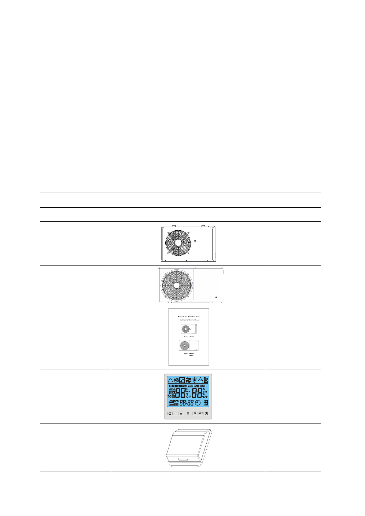
Items inside product box ……………………………………………………………………………………………………………… 2
Cycle diagram………..………….……………………….….……………………………………………………………………………… 3
SAFETY PRECAUTIONS …………………………………………………………………………………………………………….. 4
Warning ……………………………………………………………………………………………………………………………………….. 4
Cauon ……………………………………………………………………………………………………………..………………………… 5
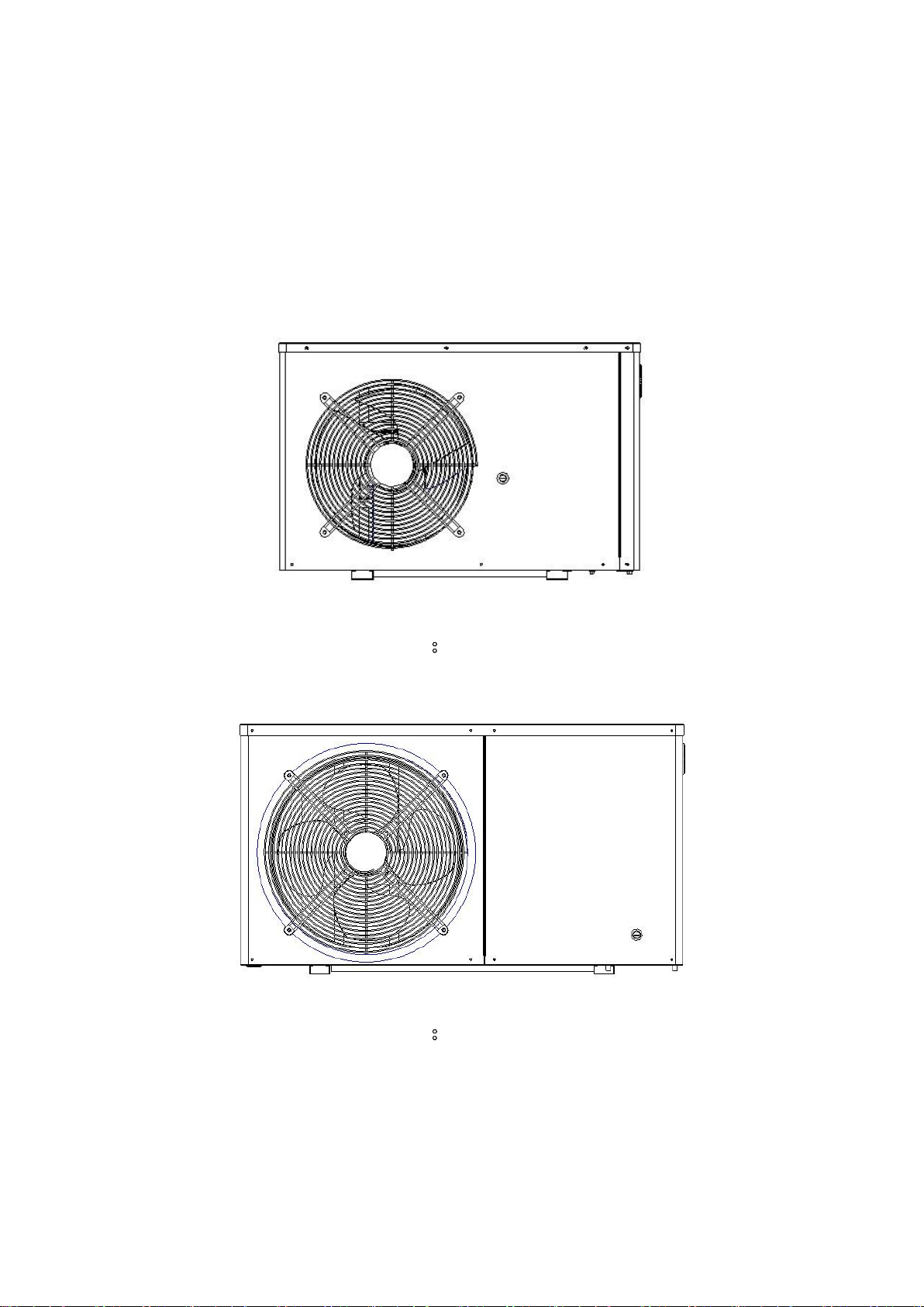
OVERVIEW OF THE UNIT ………………………………………………………………………………..………………….…….. 7
External view: SDAW3.5-220 …………………………………………………………….………………………………………….. 7
External view: SDAW4.6-220, SDAW6.7-220
SDAW3.5-220
SDAW4.6-220, SDAW6.7-220
……………………………….………………………………………………… 8
Internal view: ……………………………………………………..………………………………….…………….. 9
Internal view: ……………………………..………………………………….…………….. 10
OPERATING THE UNIT…………………………………………………………………………………………………………………..11
Features and funcon……………………………………………………………………………………………………………………. 11
User interface …………..……………………………………………………….…………………………………………………………… 11
Buons…………………………………………………….…….…………………..……………………………………….…………….… 12
LCD icons …………………………………………………….…….…………………..……………………………………….……………. 12
Controller operaons…………………………………….…….…………………..……………………………………….………… 13
PARAMETER CHECKING AND ADJUSTMENT…………………………………………………………………………….. 14
Parameter list……………………………………………….…….…………………..……………………………………….……………. 14
Malfuncons and error codes……………………….…….…………………..……………………………………….……………. 15
Wiring diagram …………………………………………….…….…………………..……………………………………….……………. 16
INSTALLATIONOF THE UNIT…………………………………………………………………………………………………… 17
Installaon guidelines ………………………………………………………………………………………………………………… 17
Precauons for selecng the locaon …………………………………………………………………………………………. 17
Selecng a locaon in cold climates …………………………………………………………………………………………….. 17
Installaon space ………………………………………………………………………………………………………………………... 18
Mounng the unit …………………………………………………………………………………………………………………………. 18
Water pipe work ……………………………………………………………………………………………………………………………. 18
Checking the water circuit …………………………………………………………………………………………………………….. 18
Connecng the water circuit …………………………………………………………………………………………………………. 19
Charging water ………………………………………………………………………………………………………………………………. 20
Piping insulaon …………………………………………………………………………………………………………………………….. 20
Field wiring …………………………………………………………………………………………………………………………………….. 20
Pre-operaon Checks ……………………………………………………………………………………………………………………. 21
Checks before inial start-up ………………………………………………………………………………………………………... 21
Seng the pump speed ………………………………………………………………………………………………………………… 22
MAINTENANCE………………………………………………………………………………………………………………….………… 23
TROUBLESHOOTING …………………………………………………………………………………………………………………. 24
General guidelines ………………………………………………………………………………………………………………………… 24
Error codes ………………………………………………………………………………………………………………………………….... 24
TEMPERATURE SENSOR R-T CONVERSION TABLE………………………………………………………………...... 26
TECHNICAL DATA……………………………………………………………………………………………………………………………28

2
INTRODUCTION
This manual includes the necessary informaon about the unit. Please read this manual carefully before
you install, operate and maintain the unit.
General informaon
The heat pump water heater is one of the most economical systems to heat the water for family
domesc use. Using free renewable energy form the air, the unit is highly efficient with low running
costs. Its efficiency can be up to 3-4 mes more than convenonal gas boiler or electrical heater.
It can offer hot water all year around. Also it can be compable with the exisng geyser in household.
Items inside product box
Thank you for choosing the heat pump water heater.
Before starting installaon, please make sure that all parts are found inside the product box.
The Unit Box
Item Image Quanty
SDAW3.5-220
1
SDAW4.6-220
SDAW6.7-220
1
Installaon and Service
Manual
1
Controller
1
Controller Cover
1
1
2
M

3
Cycle diagram
The whole cycle diagram is shown below.

4
SAFETY PRECAUTIONS
To prevent injury to the user, other people, or property damage, the following instructions must be
followed. Incorrect operation due to ignoring of instructions may cause harm or damage.
Install the unit only when it complies with local regulations, by-laws and standards. Check the main
voltage and frequency. This unit is only suitable for earthed sockets.
The following safety precautions should always be taken into account:
-Be sure to read the following WARNING before installing the unit.
-Be sure to observe the cautions specified here as they include important items related to safety.
-After reading these instructions, be sure to keep it together with the manual in a handy place for
future reference.
Do not install the unit yourself.
Incorrect installation could cause injury due to fire, electric shock, the unit falling or leakage of water.
Consult the dealer from whom you purchased the unit or a specialized installer.
Install the unit securely in a place.
When insufficiently installed, the unit could fall causing injury. When installing the unit in a small room,
please take measures (like sufficient ventilation) to prevent the asphyxia caused by the leakage of
refrigerant.
Use the specified electrical wires and attach the wires firmly to the terminal board (connection in such
a way that the stress of the wires is not applied to the sections).
Incorrect connection and fixing could cause a fire.
Be sure to use the provided or specified parts for the installation work.
The use of defective parts could cause an injury due to possible fire, electric shocks, the unit falling etc.
Perform the installation securely and please refer to the installation instructions.
Incorrect installation could cause an injury due to possible fire, electric shocks, the unit falling, leakage
of water etc.
Perform electrical work according to the installation manual and be sure to use a dedicated section.
If the capacity of the power circuit is insufficient or there is an incomplete electrical circuit, it could
result in a fire or an electric shock.
The unit must always have an earthed connection.
If the power supply is not earthed, you may not connect the unit.

5
Never use an extension cable to connect the unit to the electric power supply.
If there is no suitable, earthed wall socket available, have one installed by a recognized electrician.
Do not move/repair the unit yourself.
Improper movement or repair on the unit could lead to water leakage, electrical shock, injury or fire.
Have any repairs and/or maintenance only carried out by a recognized service engineer.
Do not plug or unplug the power supply during operation
There is a risk of fire or an electric shock
Do not touch/operate the unit with wet hands
There is a risk of fire or an electric shock
Do not place a heater or other appliances near the power cable
There is a risk of fire or an electric shock
Be cautious that water could not be poured to the product directly, do not allow water to run into
electric parts
There is a risk of fire or an electric shock
Working ambient temperature: -7°C to 45°C, working pressure:0.1MPa to 1.0MPa, fuse link: AC250V,
T3.15AL, Power cord: H07RN-F, 1.5mm²
An all-pole disconnection device which has at least 3mm clearances in all poles , and have a leakage
current that may exceed 10mA, the residual current device (RCD) having a rated residual operating
current not exceeding 30mA, and disconnection must be incorporated in the fixed wiring in
accordance with the wiring rules.
If the supply cord is damaged, it must be replaced by the manufacturer or its service agent or a
similarly qualified person in order to avoid a hazard.
This appliance has not been designed for use by persons (including children) with reduced physical,
sensorial or mental faculties or by persons without any experience or knowledge of heating systems,
unless they act under the safety and supervision of a responsible person or have received prior
training concerning the use of the appliance.
Children should be supervised to ensure that they do not play with the appliance
IF THE PRODUCT IS NOT USED FOR A LONG TIME, WE STRONGLY RECOMMEND NOT TO SWITCH
‘OFF’ THE POWER SUPPLY OF THE UNIT.
IF THE POWER IS NOT SUPPLIED, SOME SPECIAL PRODUCT-PROTECTING ACTIONS (SUCH AS
ANTI-FREEZE) WILL NOT BE PERFORMED.

6
Do not install the unit in a place where there is a chance of flammable gas leaks.
If there is a gas leak and gas accumulates in the area surrounding the unit, it could cause an explosion.
Perform the drainage/piping work according to the installation instruction.
If there is a defect in the drainage/piping work, water could leak from the unit and household goods
could get wet and be damaged.
Do not clean the unit when the power is ‘on’.
Always shut ‘off’ the power when cleaning or servicing the unit. If not, it could cause an injury due to
the high speed running fan or an electrical shock.
Do not continue to run the unit when there is something wrong or there is a strange smell.
The power supply needs to be shut ‘off’ to stop the unit; otherwise this may cause an electrical shock or
fire.
Be cautious when unpacking and installing the product.
Sharp edges could cause injury. Especially watch the edges and the fins on the heat exchanger of the
product.
Always check for gas (refrigerant) leakage after installation or repair of product.
Low refrigerant levels may cause failure of the product.
Keep level even when installing the product.
This is to avoid vibration or water leakage.
Do not put your fingers or others into the fan, or evaporator.
The ventilator runs at high speed, this could cause serious injury.

7
OVERVIEW OF THE UNIT
External view: SDAW3.5-220

8
OVERVIEW OF THE UNIT
External view: SDAW4.6-220 / SDAW6.7-220

9
Internal view: SDAW3.5-220
No. Descripon No. Descripon
1 Front panel 10 Top cover
2 Air outlet grill 11 Electrical box
3 Fan motor 12 Compressor
4 Fan 13 Water pump
5 Fan motor holder 14 Manometer
6 Side grill 15 Back right panel
7 Back holder 16 Shell & tube heat exchanger
8 Evaporator 17 Four-way valve assembly
9 Back grill 18 Pressure relief valve

10
Internal view: SDAW4.6-220 / SDAW6.7-220
No.
Descripon
No.
Descripon
1
Lefront panel
10
Manometer
2
Air outlet grill
11
Shell & tube heat exchanger
3
Fan
12
Four-way valve assembly
4
Fan motor
13
Pressure relief valve
5
Fan motor holder
14
Water pump
6
Evaporator
15
Electrical box
7
Back grill
16
Compressor
8
Top cover
17
Base assembly
9
Back right panel
18
Right front panel

11
OPERATING THE UNIT
Operating the unit comes down to operating the digital controller.
NEVER LET THE DIGITAL CONTROLLER GET WET. THIS MAY CAUSE AN ELECTRIC SHOCK OR FIRE.
NEVER PRESS THE BUTTONS OF THE DIGITAL CONTROLLER WITH A HARD, POINTED OBJECT.
THIS MAY DAMAGE THE DIGITAL CONTROLLER.
NEVER INSPECT OR SERVICE THE DIGITAL CONTROLLER YOURSELF, ASK A QUALIFIED SERVICE
PERSON TO DO THIS.
Features and functions
Basic controller functions
The basic controller functions are:
Turning the heat pump ‘ON’/’OFF’.
24 hours real time clock.
Timer ‘ON’ and timer ‘OFF’.
Parameter adjustment
User interface
-- Power ‘ON’
When turning ‘ON’ the power, whole icons are displayed on the controller screen for 3 seconds.
After checking if everything is ok, the unit enters into the standby mode, and current room
temperature is displayed on the screen.
Timer
Setting button
DOWN adjust button
Unit ‘ON’/’OFF’ button
UP adjust button
Mode button
1
2
M

12
Buons
1. Unit ON/OFF buon
Press this buon when the unit is standby, the unit can be turned ‘ON’ and runs on the seng
mode. The running mode, temperatures, mer situaon and clock me are displayed on the screen.
Press this buon again when the unit is running, the unit then will be turned ‘OFF’.
2. Mode buon
Press this buon to select the running mode at any situaon. Each me this buon is pressed, the
mode will change. It is applicable to heang & cooling unit.
(Remark: For model SDAW3.5-220, SDAW4.6-220, SDAW6.7-220, only heang mode is available.)
3. And adjust buons
These are the mul-purpose buons. Combining the seng buon, they are used for the
parameter seng, parameter checking, clock adjustment and adjustment of the mer.
4. Seng buon
This is the mul-purpose buon. Combining the adjust buons, it is used for the parameter seng,
parameter checking, clock adjustment and adjustment of the mer.
LCD icons
1. Cooling mode
The icon indicates that the current operaon mode is cooling.
(Remark: For model SDAW3.5-220, SDAW4.6-220, SDAW6.7-220, only heang mode is available.)
2. Heang mode
The icon indicates that the current operaon mode is heang.
3. Defrosng
The icon indicates that the defrosng funcon is enabled. This is an automac funcon, the system
will entry or exit the defrosng according to the inner control program. The defrosng parameters
can be changed at fieldwork. And the unit does not support manual defrosng control.
4. Le temperature display
The display shows the current water inlet temperature.
If you want to check or adjust the parameter this secon will display the relang parameter number.
In case when any malfuncon occurs, this secon will display the related error code.
5. Right temperature display
The display shows that the current water outlet temperature.
If you want to check or adjust the parameter this secon will display the related parameter value.
In case when any malfuncon occurs, this secon will display the related error code.

13
6. Clock display
The clock display shows the current time.
When reading or programming the scheduled timer, the clock display shows the action time.
7. Timer ‘ON’
The icon indicates that the timer ‘ON’ function is enabled.
8. Timer ‘OFF’
The icon indicates that the timer ‘OFF’ function is enabled.
Controller operations
1. Status checking
-When in main interface, press or button to check the system status P1 ,P2.,Inlet/outlet
temp, ambient temp (Please refer to the parameter list)
-If no action to the buttons for 5 seconds, the controller will exit status checking interface and come
back to main interface automatically.
2. Parameter checking and setting
-Press button once to enter parameter checking interface.
-In the parameter checking interface, each time the button is pressed, the parameter will
change from 0 to 9 orderly (circularly), total 10 parameters can be checked. (Please refer to
“parameter list”)
-Adjust parameter 0 and 1: during standby status, after entering parameter checking interface,
parameter 0 and parameter 1 can be set only by pressing or button. Finally setting can be
saved automatically after 10 seconds no action
-Adjust parameter 2 and 9: during standby status, press button to select the parameter you
want to adjust , then press and buttons at the same time for 3 seconds, after one buzzer
sound, enter into parameter setting interface. Press or button to set the parameter.
Finally setting can be saved automatically after 10 seconds no action
NOTE:
1) You can check and adjust the set parameters during standby mode; you cannot adjust the set parameters when
the unit is running.
2) The parameters have been set; the user cannot change the parameters optionally. Please ask a qualified service
person to do this when required.
3. Lock and unlock the buttons
-Press and buttons at the same time and hold for 5 seconds, the buttons are locked after
one buzzer sound.
-Press and buttons at the same time and hold for 5 seconds again, the buttons are

14
unlocked aer one buzzer sound.
4. buon
Press this buon for 3 seconds to set the clock me. The hour icon flashes, use the and
buons to set the exact hour(s). Press the buon again to set the exact minute(s). Aer finishing the
seng, press the buon once again to exit.
Press this buon to cancel the mer ‘ON’ (or mer ‘OFF’) funcon during the mer ‘ON’ (or mer
‘OFF’) programming.
5. buon
Press this buon for five seconds to enter the mer ‘ON’ program. The icon of ‘ON’ flashes. Use the
or buon to set the hour(s) seng me and then press it to set minute seng me.
Aer set the mer on funcon, press again to enter the mer ‘OFF’ program. The icon of ‘off’ flashes.
The method of seng mer off is the same as that of mer on.
-Press the buon again to save and exit the program or the seng can be saved automacally aer
10 seconds no acon
NOTE:
1) The mer ‘ON’ and mer ‘OFF’ funcons should be set together.
2) Press the buon to cancel the mer seng during the mer programming.
PARAMETER CHECKING AND ADUSTMENT
Parameter list
Some parameters can be checked and adjusted by the controller. Below is the parameter list.
Parameter
No.
Descripon Range Default Remarks
0 Cooling inlet water seng temp. 8 ~ 28°C 12°C Used in heang &
Cooling mode ①
1 Heang inlet water seng temp. 20 ~55°C 45°C Adjustable
2 Defrosng period 30~90 min 40 min Adjustable
3
Defrosng entry coil temp.
-30 ~ 0°C
-7°C
Adjustable
4
Defrosng exit coil temp.
2 ~ 30°C
13°C
Adjustable
5
Max defrosng cycle period
0-15 min
8 min
Adjustable
6
System parameter
1-2
2
7 Auto restart funcon 0/1 1 Adjustable
(0-No
,
1-Yes)
8
Mode selecon
0/1/2/3
3
Heang mode
②
9 Water pump working mode 0/1 1 Adjustable
(0-normal,1-specical)
(①②Remark: For model SDAW3.5-220, SDAW4.6-220, SDAW6.7-220, only heang mode is available. )

15
Some system status can be checked by the controller but cannot be adjustable. Below is the list.
Status No.
Description
Range
Remarks
IN
Inlet water temp.
-9 ~ 99°C
Real test value
OUT
Outlet water temp.
-9 ~ 99°C
Real test value
P1
Coil temp.
-9 ~ 99°C
Real test value
P2
Reserved
-9 ~ 99°C
Real test value
ROOM
Ambient temperature
-9 ~ 99°C
Real test value
Malfunctioning of the unit and error codes
When an error occurs or the protection mode is set automatically, the circuit board and the wired
controller will both display the error message.
Protection/Malfunction
Error code
Error Indicator LED
Inlet water temp. sensor failure
PP 01
☆●(One flash one black)
Outlet water temp. sensor failure
PP 02
☆☆●(2flash 1 black)
Evaporator coil temp. sensor failure
PP 03
☆☆☆●(3 flash 1 black)
Ambient temp. sensor failure
PP 05
☆☆☆☆☆●(5flash 1 black)
Too much Inlet/outlet water temp.
difference protection
PP 06
bright
Winter freezing protection
PP 07
dark
Too low outlet water temp. protection
PP 08
bright
High pressure protection
EE 01
☆☆☆☆☆☆●(6 flash 1 black)
Low pressure protection
EE 02
☆☆☆☆☆☆☆●(7flash 1 black)
Water flow protection
EE 03
☆☆☆☆☆☆☆☆●(8 flash1 black)
Too much Inlet/outlet water temp.
difference failure
EE 05
☆☆☆☆☆☆☆☆☆☆●(10 flash 1
black)
Defrost
Defrosting
indicate
☆☆☆☆☆☆☆☆……(Long flash)
Communication failure
EE 08

16
WIRING DIRGRAM

17
INSTALLATION OF THE UNIT
Installation guidelines
Precautions for selecting the location
MAKE SURE TO PROVIDE FOR ADEQUATE MEASURES IN ORDER TO PREVENT THAT THE OUTDOOR
UNIT WILL BE USED AS A SHELTER FOR SMALL ANIMALS.
SMALL ANIMALS MAKING CONTACT WITH ELECTRICAL PARTS CAN CAUSE MALFUNCTIONS, SMOKE
OR FIRE. PLEASE KEEP THE AREA AROUND THE UNIT CLEAN.
1. Choose a place solid enough to bear the weight and vibration of the unit, where the operation noise
will not be amplified.
2. Choose a location where the hot air discharged from the unit or the operation noise will not cause a
nuisance to the neighbors of the user.
3. Avoid places near a bedroom and the like, so that the operation noise will cause no trouble.
4. There must be sufficient space for carrying the unit into and out of the site.
5. There must be sufficient space for air passage and no obstructions around the air inlet and the air
outlet.
6. Locate the unit so that the noise and the discharged hot air will not annoy the neighbors.
7. The site must be free from the possibility of flammable gas leakage in a nearby place.
8. Install units, power cords and inter-unit cables at least 3m away from television and radio sets. This
is to prevent interference to images and sounds.
9. Depending on radio wave conditions, electromagnetic interference can still occur even if installed
more that 3m away.
10. In coastal areas or other places with salty atmosphere of sulfate gas, corrosion may shorten the life
of the outdoor unit.
11. Since drain flows out of the outdoor unit, do not place anything under the unit which must be kept
away from moisture.
Selecting a location in cold climates
WHEN OPERATING THE OUTDOOR UNIT IN A LOW OUTDOOR AMBIENT TEMPERATURE, BE SURE
TO FOLLOW THE INSTRUCTIONS DESCRIBED BELOW.
To prevent exposure to wind, install the outdoor unit with its suction side facing the wall.
Never install the outdoor unit at a site where the suction side may be exposed directly to wind.
To prevent exposure to wind, install a baffle plate on the air discharge side of the outdoor unit.
In heavy snowfall areas it is very important to select an installation site where the snow will not
affect the unit. If lateral snowfall is possible, make sure that the heat exchanger coil is not
affected by the snow (if necessary construct a lateral canopy).

18
Installation space
Mounting the unit
When installing the outdoor unit, please refer to “Installation guidelines” to select an appropriate
location.
1. Check the strength and level of the installation ground so that the unit will not cause any operating
vibration or noise after installation.
2. Prepare 4 sets of M8 foundation bolts, nuts and washers each (filed supply).
3. Fix the unit securely by means of the foundation bolts in accordance with the foundation drawing. It
is best to screw in the foundation bolts until their length remains 20mm above the foundation
surface.
Water pipe-work
Checking the water circuit
The water circuits must be provided by a licensed technician and must comply with all relevant
European and national regulations.
THE UNIT IS ONLY TO BE USED IN A CLOSED WATER SYSTEM. APPLICATION IN AN OPEN WATER
CIRCUIT CAN LEAD TO EXCESSIVE CORROSION OF THE WATER PIPING.
Before continuing the installation of the unit, check the following points:
The maximum water pressure is 6 bar.

19
Two stop valves are not delivered with the unit. To facilitate service and maintenance, please
install one at each water inlet/outlet. Mind position of the stop valves. Orientation of the
integrated drain and fill valves is important for servicing.
Drain taps must be provided at all low points of the system to permit complete drainage of the
circuit during maintenance.
Air vents must be provided at all high points of the system. The vents should be located at
points which are easily accessible for servicing. Do the air purge during the installation. Pls refer
to the illustration on page 3
Take care that the components installed in the field piping can withstand the water pressure.
Connecting the water circuit
Water connections must be made in accordance with the outlook diagram delivered with the unit,
respecting the water in and outlet
BE CAREFUL NOT TO DEFORM THE UNIT PIPING BY USING EXCESSIVE FORCE WHEN CONNECTING
THE PIPING. DEFORMATION OF THE PIPING CAN CAUSE THE UNIT TO MALFUNCTION.
If air, moisture or dust gets in the water circuit, problems may occur.
Therefore, always take into account the following when connecting the water circuit:
Use clean pipes only.
Hold the pipe end downwards when removing burrs.
Cover the pipe end when inserting it through a wall so that no dust and dirt can enter.
Use a good thread sealant for the sealing of the connections.
The sealing must be able to withstand the pressures and temperatures of the system.
When using non-brass metallic piping, make sure to insulate both materials from each other to
prevent galvanic corrosion.
Because brass is a soft material, use appropriate tooling for connecting the water circuit.
Inappropriate tooling will cause damage to the pipes.
THE UNIT IS ONLY TO BE USED IN A CLOSED WATER SYSTEM. APPLICATION IN AN OPEN WATER
CIRCUIT CAN LEAD TO EXCESSIVE CORROSION OF THE WATER PIPING.
NEVER USE ZN-COATED PARTS IN THE WATER CIRCUIT. EXCESSIVE CORROSION OF THESE PARTS
MAY OCCUR AS COPPER PIPING IS USED IN THE INTERNAL WATER CIRCUIT OF THE UNIT.
WHEN USING A 3-WAY VALVE OR A 2-WAY VALVE IN THE WATER CIRCUIT.
THE RECOMMENDED MAXIMUM CHANGEOVER TIME OF THE VALVE SHOULD BE LESS THAN 60
SECONDS.
This manual suits for next models
2
Table of contents
Popular Heat Pump manuals by other brands

Amana
Amana RHE30A2A Specification sheet

ZANSKAR
ZANSKAR HOTSPRING HSHPM300 manual

cec
cec GO'pac Series Installation and instruction manual

Goodman
Goodman R-410A Service instructions

Gullberg & Jansson
Gullberg & Jansson S30-3P Installation and maintenance guide

Daikin
Daikin ComfortNet DX7TC Service instructions

Atlantic
Atlantic 024306 Installation

Carrier
Carrier Heat Pump Owner's information manual

Hayward
Hayward ENERGYLINE INVERTER Series Installation & operation manual

Carrier
Carrier 25hba installation instructions

BWT
BWT PEARL HPT 12 instruction manual

Toshiba
Toshiba MCY-MAP 7HS-UL Series Engineering data book