manuals.online logo
Brands
  1. Home
  2. •
  3. Brands
  4. •
  5. Danfoss
  6. •
  7. Heat Pump
  8. •
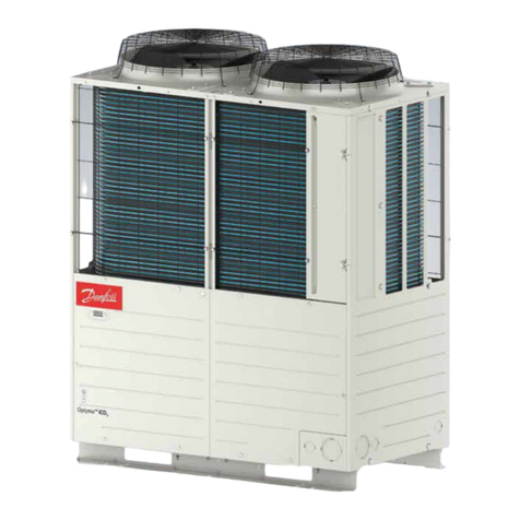
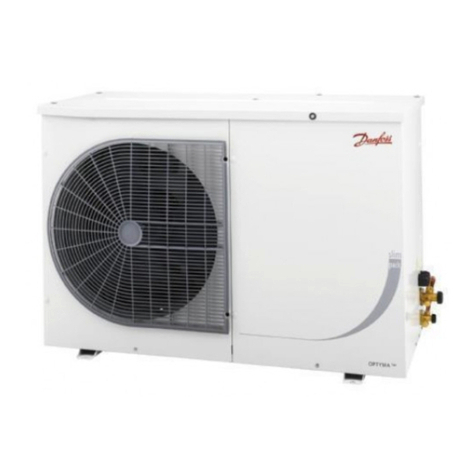
  9. Danfoss Optyma Slim Pack OP-LSHM Series User manual

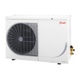
Danfoss Optyma Slim Pack OP-LSHM Series User manual

FRCC.EI.026.A5.ML Danfoss Commercial Compressors - 09/14
English / English p. 4
Français / French p. 10
Polski / Polish p. 16
Español / Spanish p. 22
Deutsch / German p. 28
Dansk / Danish p. 34
Svenska / Swedish p. 40
Português / Portuguese p. 46
Nederlands / Dutch p. 52
Suomi / Finnish p. 58
Elinika / Greek p. 64
Norsk /Norwegian p. 70
български (Bălgarski) / Bulgarian p. 76
Română / Romanian p. 82
Čeština / Czech p. 88
Русский/Russian p. 94
Italiano / Italian p. 100
INSTRUCTIONS
OPTYMA™ SLIM PACK OP-LSHM/MSUM/MSHM
FRCC.EI.026.A5.ML © Danfoss Commercial Compressors 09/142
OP-LSHM026 - 034 - 048 - 068 - 074, OP-MSHM024 - 026 - 034, OP-MSUM034 - 046 - 057
OP-LSHM015 - 018, OP-MSHM010 - 012 - 015 - 018
Instructions
3FRCC.EI.026.A5.ML © Danfoss Commercial Compressors 09/14
Instructions
OP-LSHM067 - 084 - 098, OP-MSUM068 - 080 - 093 - 099 - 108
The condensing unit must only be used for
its designed purpose(s) and within its scope of
application.
Under all circumstances, the EN378 (or
other applicable local safety regulation)
requirements must be fullled.
The condensing unit is delivered under nitro-
gen gas pressure (1 bar) and hence it cannot
be connected as it is; refer to the «installation»
section for further details.
The condensing unit must be handled with cau-
tion in the vertical position (maximum oset
from the vertical : 15°)
FRCC.EI.026.A5.02 © Danfoss Commercial Compressors 09/14
4
MADE IN INDIA
OP-MSUM034MLW05E
Code no.:
Application
Refrigerant
M.W.P. HP
114X7062
MBP
(1) R404A, R507A
(1) 28 bar
LP (1) 7 bar
IP54
(2) R134a
(2) 23 bar
(2) 5 bar
Voltage 380-400V3N~/50Hz
LRA 30,5 7,5MCC
Serial No.
Barcode Serial No:
123456CG0514
118UXXXX
A
B
C
D
E
F
G
K
H
I
J
INSTRUCTIONS
OPTYMA™ SLIM PACK OP-LSHM/MSUM/MSHM
Installation and servicing of the
condensing units by qualied
personnel only. Follow these instructions
and sound refrigeration engineering practice
relating to installation, commissioning,
maintenance and service.
A: Model
B: Code number
C: Application, Protection
D: Refrigerant
E: Housing Service Pressure
F: Supply voltage, Locked Rotor Ampere,
Maximum Current Consumption
G: Serial Number and bar code
H: Cable entry ports
I: Suction port
J: Liquid port
K: Microchannel heat exchanger
L
M
NO
L
[mm]
M
[mm]
N
[mm]
O
[mm]
250 650 550 550
Picture 1 : Minimum mounting distances
Picture 2
Picture 3
Mounting bolts (not supplied)
1 – Introduction
These instructions pertain to OptymaTM Slim
Pack condensing units OP-LSHM/MSUM/MSHM
(R507A, R404A, R134a, R22) used for refrigera-
tion systems. They provide necessary informa-
tion regarding safety and proper usage of this
product
The condensing unit includes following:
• Scroll/reciprocating compressor
• Microchannel heat exchanger
• Dual pressure switches
• Service valves Suction/ liquid
• Weather proof housing
• Filter drier
• Cranckcase heater for compressor
• Receiver with stop valve
• Sight glass
• Phase sequence relay (scroll compressors)
• Fully pre-wired electrical panel (including
main switch, compressors contactor, overload
relay)
2 – Handling and storage
• It is recommended not to open the packaging
before the unit is at the nal place for installation.
• Handle the unit with care. The packaging al-
lows for the use of a forklift or pallet jack. Use
appropriate and safe lifting equipment.
• Store and transport the unit in an upright position.
• Store the unit between -35°C and 50°C.
• Don’t expose the packaging to rain or corro-
sive atmosphere.
• After unpacking, check that the unit is com-
plete and undamaged.
3 – Installation precautions
Do not braze as long the condensing unit is
under pressure.
Never place the unit in a ammable atmosphere
Place the unit in such a way that it is not blocking
orhindering walking areas,doors,windowsorsimilar.
• Ensure adequate space around the unit for air
circulation and to open doors. Refer to pic-
ture1 for minimal values of distance to walls.
• Avoid installing the unit in locations which are dai-
ly exposed to direct sunshine for longer periods.
• Avoid installing the unit in aggressive and
dusty environments.
• Ensure a foundation with horizontal surface
(less than 3° slope), strong and stable enough
to carry the entire unit weight and to elimi-
nate vibrations and interference.
• The unit ambient temperature may not ex-
ceed 50°C during o-cycle.
• Ensure that the power supply corresponds to
the unit characteristics (see nameplate).
• When installing units for HFC refrigerants,
use equipment specically reserved for HFC
refrigerants which was never used for CFC or
HCFC refrigerants.
• Use clean and dehydrated refrigeration-grade
copper tubes and silver alloy brazing material.
• Use clean and dehydrated system components.
• The suction piping connected to the com-
pressor must be exible in 3 dimensions to
dampen vibrations. Furthermore piping has
to be done in such a way that oil return for the
compressor is ensured and the risk of liquid
slug over in compressor is eliminated.
4 – Installation
• The installation in which the condensing unit
is installed must comply to EEC Pressure direc-
tive (PED) no. 97/23/EC. The condensing unit
itself is not a ”unit” in the scope this directive.
• The unit must be securely installed on a stable
and rigid support, and xed from the begin-
ning. See picture 2.
• It is recommended to install the unit on rub-
ber grommets or vibration dampers (not
supplied).
• Slowly release the nitrogen holding charge
through the schrader port.
• Connect the unit to the system as soon as pos-
sible to avoid oil contamination from ambient
moisture.
• Avoid material entering into the system while
cutting tubes. Never drill holes where burrs
cannot be removed.
• Braze with great care using state-of-the-art tech-
nique and vent piping with nitrogen gas ow.
• Connect the required safety and control de-
vices. When the schrader port is used for this,
remove the internal valve.
• It is recommended to insulate the suction
pipe up to the compressor inlet with 19 mm
thick insulation.
5
FRCC.EI.026.A5.02 © Danfoss Commercial Compressors 09/14
Instructions
5 – Leak detection
Never pressurize the circuit with oxygen or
dry air. This could cause re or explosion.
• Do not use dye for leak detection.
• Perform a leak detection test on the complete
system.
• The maximum test pressure is 32 bar.
• When a leak is discovered, repair the leak and
repeat the leak detection.
6 – Vacuum dehydration
• Never use the compressor to evacuate the system.
• Connect a vacuum pump to both the LP & HP
sides.
• Pull down the system under a vacuum of 500
μm Hg (0.67 mbar) absolute.
• Do not use a megohmmeter nor apply power
to the compressor while it is under vacuum as
this may cause internal damage.
7 – Electrical connections
• Switch o and isolate the main power supply.
• Ensure that power supply can not be switched
on during installation.
• All electrical components must be selected as
per local standards and unit requirements.
• Refer to wiring diagram for electrical connec-
tions details.
• Ensure that the power supply corresponds to
the unit characteristics and that the power
supply is stable (nominal voltage ±10% and
nominal frequency ±2,5 Hz).
• Dimension the power supply cables accor-
ding to unit data for voltage and current.
• Protect the power supply and ensure correct
earthing.
• Make the power supply according to local
standards and legal requirements.
•
The unit is equipped with high and low pres-
sure switches, which directly cut the power
supply to the compressor in case of activation.
Parameters for high and low pressure cut outs
should be set by installer considering compres-
sor model, refrigerant and application. Units
with Danfoss MLZ, LLZ and NTZ compressors
are also equipped with phase sequence relay to
protect the unit against phase loss/sequence/
asymmetry and under-/over-voltage.
For units with a 3-phase scroll compressor, cor-
rect phase sequence for compressor rotation
direction shall be observed.
• Determine the phase sequence by using a
phase meter in order to establish the phase
orders of line phases L1, L2 and L3.
• Connect line phases L1, L2 and L3 to main
switch terminals T1, T2 and T3 respectively.
8 – Filling the system
• Wear protective stu like goggles and protec-
tive gloves.
• Never start the compressor under vacuum.
Keep the compressor switched o.
• Before charging the refrigerant, verify that the
oil level is between ¼ and ¾ on the compressor
oil sight glass. If additional oil is required please
refer to the compressors label for type of oil.
• Use only the refrigerant for which the unit is
designed for.
• Fill the refrigerant in liquid phase into the
condenser or liquid receiver. Ensure a slow
charging of the system to 4 – 5 bar for R404A /
R507A or R22 and approx. 2 bar for R134a.
• Do not put liquid refrigerant through suction line.
• It is not allowed to mix additives with the oil
and/or refrigerant
• The remaining charge is done until the instal-
lation has reached a level of stable nominal
condition during operation.
• Never leave the lling cylinder connected to
the circuit.
9 – Verification before commissioning
Use safety devices such as safety pressure
switch and mechanical relief valve in com-
pliance with both generally and locally appli-
cable regulations and safety standards. Ensure
that they are operational and properly set.
Check that the settings of high-pressure swit-
ches and relief valves don’t exceed the maximum
service pressure of any system component.
• Verify that all electrical connections are properly
fastened and in compliance with local regulations.
• When a crankcase heater is required, it must
be energized at least 12 hours before initial
start-up and start-up after prolonged shut-
down period.
10 – Start-up
• Never start the unit when no refrigerant is
charged.
• All service valves must be in the open position.
See picture 3.
• Check compliance between unit and power
supply.
• Check that the crankcase heater is working.
• Check that the fan can rotate freely.
• Check that the protection sheet has been re-
moved from the backside of condenser.
• Balance the HP/LP pressure.
• Energize the unit. It must start promptly. If
the compressor does not start, check wiring
conformity, voltage on terminals and se-
quence phase.
• Eventual reverse rotation of a 3-phase com-
pressor can be detected by following phe-
nomena; unit doesn’t start, the compressor
doesn’t build up pressure, it has abnormally
high sound level and abnormally low power
consumption. In such case, shut down the
unit immediately and connect the phases to
their proper terminals.
• If the rotation direction is correct the low pres-
sure indication on the low pressure gauge
shall show a declining pressure and the high
pressure indication on the high pressure
gauge shall show an increasing pressure.
11 – Check with running unit
• Check the fan rotation direction. Air must ow
from the condenser towards the fan.
• Check current draw and voltage.
• Check suction superheat to reduce risk of
slugging.
• When a sight glass is provided observe the oil
level at start and during operation to conrm
that the oil level remains visible.
• Respect the operating limits.
• Check all tubes for abnormal vibration. Move-
ments in excess of 1.5 mm require corrective
measures such as tube brackets.
• When needed, additional refrigerant in liquid
phase may be added in the low-pressure side as
far away as possible from the compressor. The
compressor must be operating during this pro-
cess.
• Do not overcharge the system.
• Never release refrigerant to atmosphere.
• Before leaving the installation site, carry out
a general installation inspection regarding
cleanliness, noise and leak detection.
• Record type and amount of refrigerant charge
as well as operating conditions as a reference
for future inspections.
12 – Maintenance
Always switch o the unit at main switch
before remove fan panel.
Internal pressure and surface temperature
are dangerous and may cause permanent injury.
Maintenance operators and installers require
appropriate skills and tools.Tubing temperature
may exceed 100°C and can cause severe burns.
Ensure that periodic service inspections to
ensure system reliability and as required by local
regulations are performed.
To prevent system related problems, following
Periodic maintenance is recommended:
• Verify that safety devices are operational and
properly set.
• Ensure that the system is leak tight.
• Check the compressor current draw.
• Conrm that the system is operating in a way
consistent with previous maintenance re-
cords and ambient conditions.
• Check that all electrical connections are still
adequately fastened.
• Keep the unit clean and verify the absence of
rust and oxidation on the unit components,
tubes and electrical connections.
The condenser must be checked at least once
a year for clogging and be cleaned if deemed
necessary. Access to the internal side of the
condenser takes place through the fan panel.
Microchannel coils tend to accumulate dirt on
the surface rather than inside, which makes
them easier to clean than n-&-tube coils.
• Switch o the unit at main switch before re-
move any panel from the condensing unit.
• Remove surface dirt, leaves, bres, etc. with
a vacuum cleaner, equipped with a brush or
other soft attachment. Alternatively, blow
compressed air through the coil from the in-
side out, and brush with a soft bristle. Do not
use a wire brush. Do not impact or scrape the
coil with the vacuum tube or air nozzle.
If the refrigerant system has been opened, the
system has to be ushed with dry air or nitrogen
to remove moisture and a new lter drier has to
be installed. If evacuation of refrigerant has to
be done, it shall be done in such a way that no
refrigerant can escape to the environment.
13 - Warranty
Always transmit the model number and serial num-
ber with any claim led regarding this product.
The product warranty may be void in following
cases:
• Absence of nameplate.
• External modications; in particular, drilling,
welding, broken feet and shock marks.
• Compressor opened or returned unsealed.
• Rust, water or leak detection dye inside the
compressor.
• Use of a refrigerant or lubricant not approved
by Danfoss.
• Any deviation from recommended instruc-
tions pertaining to installation, application or
maintenance.
• Use in mobile applications.
• Use in explosive atmospheric environment.
• No model number or serial number transmit-
ted with the warranty claim.
14 – Disposal
Danfoss recommends that condensing
units and oil should be recycled by a
suitable company at its site.
FRCC.EI.026.A5.02 © Danfoss Commercial Compressors 09/14
6
Instructions
98
765
4
10 2 3
=
+
DATE
SHEET
OF
DRAWING-NO.
DRW
APP REV DATE
APPR
NORM DIN61346
DEPT.
NAME
1
1
wiring diagram/Schaltplan/plan de circuits
u249499
u249499
21
22
-K1
3A
1
2
-F3
95
96
97
98
-F2
16.12.13
118R0142
(114X7077)
(114X7078)
(114X7079)
1
2
3
4
5
6
-K1
xxA
5
6
3
4
1
2
-F2
13
14
11
13
10
12
-K2
M
1~
SCR
PE
-M1
BN
-F1
BU
PE
.
-X1
230V1N~/50Hz
L PEN
BN
BU
MG73BF
SM500
16 18 15
L1
L2
L3
P
N
26 28 25
-A1*
BK
2
.
4
.
3
.
BU
BN
BN
BN
BN
PE
.
-X1
M
1~
-M2
-S1*
BK BN
1
.
2
1
-E1
BU
N2
.
5
.
6
.
BN
P
1
2
PE
-B1*
BN
7
.
BU
BN BN
8
.
P<
P>
B
C
A
D
PE
-B2
PE
.
-X1
-C3
BK
N1
.
A1
A2
-K1
OP-LSHM015SCW05G
OP-LSHM018SCW05G
OP-MSHM010SCW05G
OP-MSHM012SCW05G
OP-MSHM015SCW05G
(114X7081)
(114X7082)A model 06.02.14 RH
CC-RCU
5,3A
6,3A
6,8A
5,8A
5,5A
OP-MSHM010SCW05G
OP-MSHM012SCW05G
OP-MSHM015SCW05G
OP-LSHM015SCW05G
OP-LSHM018SCW05G
-C2
98
765
4
10 2 3
=
+
DATE
SHEET
OF
DRAWING-NO.
DRW
REV DATE
APPR
NORM DIN61346
DEPT.
NAME
1
1
wiring diagram/Schaltplan/plan de circuits
u249499
u249499
21
22
-K1
3A
1
2
-F3
95
96
97
98
118R0143
BK
2 43
BU
BN
BN
BN
BN
PE
-X1
M
1~
-M2 -S1*
BK BN
1
2
1
-E1
BU
N2 5 6
BN
P
1
2
PE
-B1*
BN
7
BU
BN BN
8
P<
P>
B
C
A
D
PE
-B2
PE
-X1
BK
N1
-C3
A1
A2
-K1
MG73BF
SM500
16 18 15
L1
L2
L3
P
N
26 28 25
-A1*
17.12.13
model 02.06.14 RH
CC-RCU
(114X7084)
(114X7083)
(114X7080) OP-LSHM026AJW05G
OP-LSHM034AJW05G
OP-MSHM018SCW05G
OP-MSHM026AJW05G
OP-MSHM034AJW05G (114X7086)
(114X7085)
OP-LSHM048NTW05G
OP-LSHM068NTW05G
(114X7087)
(114X7089)
RH
M
1~
SCR
PE
-M1
1
2
3
4
5
6
-K1
xxA
5
6
3
4
1
2
-F2
-C2
-C1
-R1
BN
BU
5
2
1
44
5
-K2
BL
BK
BR
-F4
OP-.......AJW05G
OP-......SCW05G
BN
-F1
BU
230V1N~/50Hz
L PEN
PE
-X1
OP-......FHW05G
NT,FH model05.09.14
APP
A
B
OP-LSHM074FHW05G (114X7095)
6,7AOP-MSHM018SCW05G
OP-LSHM026AJW05G
OP-LSHM034AJW05G
OP-LSHM048NTW05G
OP-LSHM068NTW05G
OP-LSHM074FHW05G
7,9A
10A
11A
17A
13A
15A
OP-MSHM026AJW05G
OP-MSHM034AJW05G
OP-MSHM024AJW05G 10A
-F2
24A
Code G : OP-MSHM010 - 012 - 015, OP-LSHM015 - 018
Code G : OP-LSHM026 - 034 - 048 - 068 - 074, OP-MSHM018 - 024 - 026 - 034
Legend
BK black
BU blue
BN brown
GY grey
RD red
WH white
A1* Voltage relay (option)
B1* Fan speed controller (option)
B2 High and Low pressure switch
C1 Run capacitor compressor
C2 Start capacitor compressor
C3 Run capacitor fan
E1 Crankcase heater
F1, F3 Fuse (control circuit)
F2 Overload relay
F4 Compressor thermal protector
M1 Compressor
M2 Fan motor
K1 Contactor
K2 Start relay
R1 Bleeder resistor
S1* Room thermostat (option)
X1 Terminals
* Option (remove bridge)
FRCC.EI.026.A5.02 © Danfoss Commercial Compressors 09/14 7
Instructions
98
765
4
10 2 3
=
+
DATE
SHEET
OF
DRAWING-NO.
DRW
APP REV DATE
APPR
NORMDIN61346
DEPT.
NAME
1
1
wiring diagram/Schaltplan/plan de circuits
u249499
u249499
BK
2 4
3
BU
BN
BN
BN
BN
A1
A2
-K1
PE
-X1
118R0112
MG73BF
SM500
16 18 15
L1
L2
L3
P
N
26 28 25
-A1
M
1~
-M2-S1*
21
22
-K1
BK BN
1
2
1
-E1
BK
N1
BU
N2
3A
1
2
-F3
95
96
97
98
5 6
BN
P
1
2
PE
-B1*
BN
7
BU
BN BN
8
P<
P>
B
C
A
D
PE
-B2
PE
-X1
-F2
BK
BN
-C1
-R1
GY
M
1~
S C R
PE
-M1
1
2
3
4
5
6
-K1
xxA
5
6
3
4
1
2
-F2
BU
BN
BN
-F1
BU
PE
-X1
230V1N~/50Hz
L PEN
16.12.13
a model RH
OP-MSUM034MLW05G
OP-MSUM046MLW05G
CC-RCU
06.02.14
OP-MSUM057MLW05G
19A
25A
26A
(114X7061)
(114X7063)
(114X7065)
OP-MSUM034MLW05G
OP-MSUM046MLW05G
OP-MSUM057MLW05G
a model RH
Commercial Compressors
16.06.14
-C3
98
765
4
10 23
=
+
DATE
SHEET
OF
DRAWING-NO.
DRW
APP REV DATE
APPR
NORMDIN61346
DEPT.
NAME
1
1
wiring diagram/Schaltplan/plan de circuits
u249499
u249499
2 4
3
BN
BN
BN
A1
A2
-K1
MG73BF
SM500
16 18 15
L1
L2
L3
P
N
26 28 25
-A1
-S1*
21
22
-K1
5 6
BN
P
1
2
PE
-B1*
BN
7
BU
BN BN
8
P<
P>
B
C
A
D
PE
-B2
PE
-X1
-F2
CC-RCU
OP-MSUM068MLW05G
OP-MSUM080MLW05G
32A
38A
BK
BU
BN
WH
WH
1~
M
GNYE
-M2
BK BN
1
BK
N1 N2
3A
1
2
-F3
95
96
97
98
BK
BN
-C1
-R1
GY
M
1~
SCR
PE
-M1
1
2
3
4
5
6
-K1
xxA
5
6
3
4
1
2
-F2
BU
BN
BN
-F1
BU
PE
-X1
230V1N~/50Hz
L PEN
S
-X1
BU
PE
-X1
2
1
-E1
(114X7067)
(114X7069)
OP-MSUM068MLW05G
OP-MSUM080MLW05G
16.06.14
Commercial Compressors 118R0161
BN
-C3
Code G : OP-MSUM034 - 046 - 057
Code G : OP-MSUM068 - 080
Legend
BK black
BU blue
BN brown
GY grey
RD red
WH white
A1* Voltage relay (option)
B1* Fan speed controller (option)
B2 High and Low pressure switch
C1 Run capacitor compressor
C2 Start capacitor compressor
C3 Run capacitor fan
E1 Crankcase heater
F1, F3 Fuse (control circuit)
F2 Overload relay
F4 Compressor thermal protector
M1 Compressor
M2 Fan motor
K1 Contactor
K2 Start relay
R1 Bleeder resistor
S1* Room thermostat (option)
X1 Terminals
* Option (remove bridge)
FRCC.EI.026.A5.02 © Danfoss Commercial Compressors 09/14
8
Instructions
98
765
4
10 2 3
=
+
DATE
SHEET
OF
DRAWING-NO.
DRW
DATE
APPR
NORM DIN61346
DEPT.
NAME
1
1
u249499
u249499
118R0113
23.11.12
CC-RCU
wiring diagram/Schaltplan/plan de circuits
Commercial Compressors
3A
1
2
-F3
95
96
97
98
1
2
3
4
5
6
-K1
BK
GY
BN
M
3~
-M1
xxA
5
6
3
4
1
2
-F2
BK
BU
BN
BN
PE
-X1
M
1~
-M2 -S1*
BK
2
1
-E1
BU
BK
BN
P
1
2
PE
-B1*
BU
BN
PE
-X1
P<
P>
B
C
A
D
PE
-B2
2 43
BN
BN
BN
1N2N1 5 6
BN
7
BN
8
21
22
-K1
A1
A2
-K1
BN
BK
GY
BU
PE
-X1
380-400V3N~/50Hz
L1 L2 PEL3 N
1
2
3
4
5
6
7
8
-F1
MG73BF
SM500
16 18 15
L1
L2
L3
P
N
26 28 25
-A1*
(114X7088)
(114X7090)
OP-LSHM048NTW05E
OP-LSHM068NTW05E
(114X7066)
(114X7062)
(114X7064)
OP-MSUM057MLW05E
OP-MSUM034MLW05E
OP-MSUM046MLW05E OP-MSHM026AJW05E
OP-MSHM034AJW05E
(114X7093)
(114X7094)
RH
RH
16.06.14
26.08.14
RH
-C3
-A1* -F2
X
X
X
-
-
OP-MSUM057MLW05E
OP-MSUM046MLW05E
OP-MSUM034MLW05E
OP-LSHM048NTW05E
OP-LSHM068NTW05E
10A
9,5A
7,0A
4,8A
8,4A
-
-
OP-MSHM026AJW05E
OP-MSHM034AJW05E
4,0A
4,8A
-
APP
c
d
e
REV
models
-A1*
05.09.14AJ,FH models
OP-LSHM074FHW05E 7,9A
Code G : OP-MSUM093
Code E : OP-LSHM048 - 068 - 074, OP-MSHM026 - 034, OP-MSUM034 - 046 - 057
98
765
4
10 2 3
=
+
DATE
SHEET
OF
DRAWING-NO.
DRW
APP REV DATE
APPR
NORM DIN61346
DEPT.
NAME
1
1
u249499
u249499
CC-RCU
Commercial Compressors
wiring diagram/Schaltplan/plan de circuits
(114X7098)
OP-MSUM093MLW06G 118R0157
03.09.14
43
BN
BN
BN
A1
A2
-K1
BK
2
BK
BU
BN
WH
WH
1~
M
GNYE
-M2
21
22
-K1
95
96
97
98
3A
1
2
-F3
BK BN
1
BK
N1
BU
N2
MG73BF
SM500
16 18 15
L1
L2
L3
P
N
26 28 25
-A1
PE
-X1
2
1
-E1
-C3
1
2
3
4
5
6
-K1
xxA
5
6
3
4
1
2
-F2
BU
BN
BK
BN
BU
-C2
M
1~
SCR
PE
-M1
-R1
-C1
-R2
5
2
1
5
-K2
-S1*
BN
-F1
BU
230V1N~/50Hz
L PEN
PE
-X1
5 6
BN
P
2
1
PE
-B1
BN
7
BU
BN BN
8
PE
-X1
P<
P>
B
C
A
D
PE
-B2
-F2
40AOP-MSUM093MLW06G
Legend
BK black
BU blue
BN brown
GY grey
RD red
WH white
A1* Voltage relay (option)
B1* Fan speed controller (option)
B2 High and Low pressure switch
C3 Run capacitor fan
E1 Crankcase heater
F1, F3 Fuse (control circuit)
F2 Overload relay
F4 Compressor thermal protector
M1 Compressor
M2 Fan motor
K1 Contactor
K2 Start relay
R1 Bleeder resistor
S1* Room thermostat (option)
X1 Terminals
* Option (remove bridge)
Danfoss can accept no responsibility for possible errors in catalogues, brochures and other printed material. Danfoss reserves the right to alter its products without notice. This
also applies to products already on order provided that such alterations can be made without subsequential changes being necessary in specications already agreed. All trade-
marks in this material are property of the respective companies. Danfoss and the Danfoss logotype are trademarks of Danfoss A/S. All rights reserved.
FRCC.EI.026.A5.02 - September 2014 Copyright Danfoss Commercial Compressors - DSS - 09/14
Instructions
Code E : OP-MSUM068 - 080 - 099 - 108, OP-LSHM084 - 098
98
765
4
10 23
=
+
DATE
SHEET
OF
DRAWING-NO.
DRW
APP REV DATE
APPR
NORMDIN61346
DEPT.
NAME
1
1
u249499
u249499
BN
-S1*
BN
P
1
2
PE
-B1*
BU
BN
PE
-X1
P<
P>
B
C
A
D
PE
-B2
2 4
3
BN
BN
56
BN
7
BN
8
-F2
21
22
-K1
A1
A2
-K1
MG73BF
SM500
16 18 15
L1
L2
L3
P
N
26 28 25
-A1
CC-RCU
13A
15A
16A
15A
OP-MSUM068MLW05E
OP-MSUM080MLW05E
OP-MSUM099MLW05E
OP-MSUM108MLW05E
OP-LSHM067LLW05E
OP-LSHM084LLW05E
OP-LSHM098LLW05E
12A
15A
15A
(114X7092)
(114X7075)
(114X7091)OP-LSHM067LLW05E
OP-LSHM084LLW05E
OP-LSHM098LLW05E
(114X7068)
(114X7070)
(114X7072)
(114X7071)
OP-MSUM068MLW05E
OP-MSUM080MLW05E
OP-MSUM099MLW05E
OP-MSUM108MLW05E
16.06.14
Commercial Compressors
118R0160
wiring diagram/Schaltplan/plan de circuits
BK
BU
BN
WH
WH
1~
M
GNYE
-M2
3A
1
2
-F3
95
96
97
98
1
2
3
4
5
6
-K1
BK
GY
BN
M
3~
-M1
xxA
5
6
3
4
1
2
-F2
BK
BU
BK
BN
1
N2
N1
BN
BK
GY
BU
PE
-X1
380-400V3N~/50Hz
L1 L2 PEL3 N
1
2
3
4
5
6
7
8
-F1
2
1
-E1
PE
-X1
BN
-C3
Legend
BK black
BU blue
BN brown
GY grey
RD red
WH white
A1* Voltage relay (option)
B1* Fan speed controller (option)
B2 High and Low pressure switch
C1 Run capacitor compressor
C2 Start capacitor compressor
C3 Run capacitor fan
E1 Crankcase heater
F1, F3 Fuse (control circuit)
F2 Overload relay
F4 Compressor thermal protector
M1 Compressor
M2 Fan motor
K1 Contactor
K2 Start relay
R1 Bleeder resistor
S1* Room thermostat (option)
X1 Terminals
* Option (remove bridge)
Le groupe de condensation doit être utilisé
uniquement dans le ou les buts pour lesquels
il a été conçu et en respectant sa plage d'uti-
lisation.
En toutes circonstances, la directive EN378
(ou une autre réglementation de sécurité
locale applicable) doit être respectée.
Le groupe de condensation est livré à une
pression d’azote de 1bar et ne doit donc pas
être raccordé en l’état; reportez-vous à la sec-
tion «installation» pour plus de détails.
Le groupe de condensation doit être manipulé
avec précaution et en position verticale (incli-
naison maximale: 15°)
FRCC.EI.026.A5.04 © Danfoss Commercial Compressors 09/14
10
MADE IN INDIA
OP-MSUM034MLW05E
Code no.:
Application
Refrigerant
M.W.P. HP
114X7062
MBP
(1) R404A, R507A
(1) 28 bar
LP (1) 7 bar
IP54
(2) R134a
(2) 23 bar
(2) 5 bar
Voltage 380-400V3N~/50Hz
LRA 30,5 7,5MCC
Serial No.
Barcode Serial No:
123456CG0514
118UXXXX
A
B
C
D
E
F
G
K
H
I
J
INSTRUCTIONS
OPTYMA™ SLIM PACK OP-LSHM/MSUM/MSHM
L'installation et l'entretien des groupes
de condensation doivent être eectués
uniquement par dupersonnelqualié.
Respectez ces instructions et de bonnes
pratiques d'ingénierie de la réfrigération pour
l'installation,lamiseenservice,lamaintenance
et l'entretien.
A: Modèle
B
: Référence - Code
C: Application, Protection
D:Réfrigérant
E
: Pression de service
F: Tension d’alimentation, Intensité en rotor
bloqué, Consommation de courant maximum
G: N° de série et code EAN
H:Orices d'entrée de câble
I: Orice d'aspiration
J: Orice de liquide
K: Échangeur de chaleur à microcanaux
L
M
NO
L
(mm)
M
[mm]
N
[mm]
O
[mm]
250 650 550 550
Illustration 1: Distances de montage minimum
Illustration 2
Illustration 3
Boulons de montage (non fournis)
1 – Introduction
Ces instructions concernent les groupes de conden-
sation OptymaTM Slim Pack OP-LSHM/MSUM/MSHM
(R507A, R404A, R134a, R22) utilisés pour les systèmes
de réfrigération. Elles fournissent les informations
nécessaires pour la sécurité et l’utilisation appropriée
de ce produit
Le groupe de condensation comprend les éléments
suivants:
• Compresseur piston/scroll
• Échangeur de chaleur à microcanaux
• Pressostats haute/basse pression
• Vannes de service, aspiration/liquide
• Capot résistant aux intempéries
• Filtre déshydrateur
• Résistance de carter pour le compresseur
• Réservoir avec vanne d’arrêt
• Voyant liquide
• Contacteur de phase (compresseurs scroll)
• Panneau électrique entièrement précâblé (y compris
sectionneur principal, contacteur de compresseur,
relais de surcharge)
2 – Manipulation et stockage
• Il est recommandé de ne pas ouvrir l'emballage
avant d'avoir positionné le groupe à son emplace-
ment d'installation
• Manipulez le groupe avec soin. L'emballage permet
l'utilisation d'un chariot élévateur ou d'un transpa-
lette. Utilisez un équipement de levage approprié et
sûr.
• Stockez et transportez le groupe en position verti-
cale.
• Stockez le groupe à une température comprise entre
-35°C et 50°C.
• N'exposez pas l'emballage à la pluie ou à une atmos-
phère corrosive.
• Après le déballage, vériez que le groupe est com-
plet et qu'il n'est pas endommagé.
3 – Précautions d'installation
Ne pas braser tant que le groupe de condensation
est sous pression.
Ne placez jamais le groupe dans une atmosphère
inammable.
Placez le groupe de manière à ne pas bloquer ou
gêner le passage, les portes, les accès, etc.
• Assurez-vous de laisser un espace adéquat autour du
groupe, an de permettre la circulation de l’air et
l’ouverture des portes. Référez-vous à l’illustration 1
pour obtenir les distances minimales à respecter
entre le groupe et les murs.
• Évitez d’installer le groupe à un emplacement expo-
sé quotidiennement au rayonnement direct du soleil
pendant de longues périodes.
• Évitez d’installer le groupe dans un environnement
agressif et poussiéreux.
• Assurez-vous de disposer d’une fondation horizon-
tale (inclinaison inférieure à 3°), susamment stable
et résistante pour pouvoir supporter l’intégralité du
poids du groupe et éliminer les vibrations et les in-
terférences.
• La température ambiante d’utilisation du groupe ne
doit pas dépasser 50°C lors du cycle d’arrêt.
• Assurez-vous que l’alimentation électrique corres-
pond aux caractéristiques du groupe (voir la plaque
signalétique).
• Lors de l’installation de groupes pour réfrigérants
HFC, utilisez l’équipement spécialement réservé aux
réfrigérants HFC n’ayant jamais été utilisé pour des
réfrigérants CFC ou HCFC.
• Utilisez des tubes en cuivre pour réfrigération,
propres et déshydratés, et un matériau de brasage
présentant un pourcentage d’argent.
• Utilisez des composants de système propres et dés-
hydratés.
• La tuyauterie d’aspiration raccordée au compresseur
doit être exible dans les 3 dimensions, an d’amor-
tir les vibrations. En outre, la tuyauterie doit être ins-
tallée de manière à assurer le retour d’huile du com-
presseur et à éviter tout risque d’accumulation de
liquide dans le compresseur.
4 – Installation
• L'installation dans laquelle le groupe de condensa-
tion est installé doit être conforme à la directive EEC
relative aux systèmes sous pression n° 97/23/EC. Le
groupe de condensation en lui-même ne constitue
pas un «groupe» au sens de cette directive.
• Le groupe doit être installé sur un support stable et
rigide et xé dès le départ. Voir illustration 2
•
Il est recommandé d’installer le groupe sur des
silent blocs ou des amortisseurs de vibrations
(non fournis).
• Libérez lentement la charge d’azote d’attente, par
l’orice schrader.
• Raccordez le groupe au système dès que possible,
pour éviter toute contamination de l’huile par l’hu-
midité ambiante.
• Évitez toute entrée de matériau dans le système lors
de la coupe des tubes. Ne percez jamais de trous à
des emplacements où les copeaux ne peuvent être
éliminés.
• Brasez très soigneusement, en utilisant les tech-
niques les plus récentes et pointues, et dégazez les
tuyauteries au moyen d’un ux d’azote.
• Raccordez les dispositifs de sécurité et de contrôle
11FRCC.EI.026.A5.04 © Danfoss Commercial Compressors 09/14
Instructions
requis. En cas d’utilisation de l’orice schrader à cet
eet, retirez la valve interne.
• Il est recommandé d’isoler le tube d’aspiration
jusqu’à l’entrée du compresseur avec une isolation
de 19mm d’épaisseur.
5 – Détection de fuites
N'utilisez jamais d'oxygène ou d'air sec pour mettre
le circuit sous pression. Vous pourriez causer un incen-
die ou une explosion.
• N'utilisez pas de traceur pour la détection de fuites.
• Eectuez un test de détection de fuites sur le sys-
tème complet.
• La pression de test maximum est de 32bar.
• Si vous détectez une fuite, réparez-la et répétez la
détection de fuites.
6 – Déshydratation sous vide
• N'utilisez jamais le compresseur pour faire le vide
dans le système.
• Raccordez une pompe à vide aux côtés BP et HP.
• Faites le vide dans le système, à une pression absolue
de 500µmHg (0,67mbar).
• N'utilisez pas de mégohmmètre et ne mettez pas le
compresseur sous tension lorsqu'il se trouve sous
vide, car cela peut entraîner des dommages internes.
7 – Raccordements électriques
• Coupez et isolez l'alimentation électrique secteur.
• Assurez-vous qu'il est impossible de mettre l'alimen-
tation sous tension lors de l'installation.
• Tous les composants électriques doivent être sélec-
tionnés conformément aux normes locales et aux
exigences du groupe.
• Référez-vous au schéma de raccordement électrique
pour plus de détails.
• Assurez-vous que l'alimentation électrique corres-
pond aux caractéristiques du groupe et qu'elle est
stable (tension nominale ±10% et fréquence nomi-
nale ±2,5Hz)
• Dimensionnez les câbles de l'alimentation confor-
mément aux données du groupe relatives à la ten-
sion et au courant.
• Protégez l'alimentation et assurez-vous de sa bonne
mise à la terre.
• Assurez-vous que l’alimentation est conforme aux
normes locales et aux exigences légales.
• Le groupe est équipé de pressostats haute pression/
basse pression, qui coupent directement l’alimenta-
tion du compresseur en cas d’activation. Les para-
mètres des coupures basse pression et haute pres-
sion doivent être dénis par l’installateur en tenant
compte du modèle de compresseur, du uide frigori-
gène et de l’application. Les groupes munis de com-
presseurs Danfoss MLZ, LLZ et NTZ sont aussi équi-
pés d’un contacteur de phase pour protéger le
groupe contre la perte, les défauts d’ordre et l’asy-
métrie des phases ainsi que la sous-tension ou la
surtension.
Pour les groupes équipés d’un compresseur Scroll tri-
phasé, il est impératif de respecter l’ordre des phases
adéquat pour le sens de rotation du compresseur.
• Déterminez l’ordre des phases à l’aide d’un phase-
mètre, an d’établir l’ordre des phases des lignes L1,
L2 et L3.
• Raccordez les phases des lignes L1, L2 et L3 aux
bornes de l’interrupteur principal T1, T2 et T3 respec-
tivement.
8 – Remplissage du système
• Portez des équipements de protection tels que des
gants et des lunettes de protection.
• Ne démarrez jamais le compresseur lorsqu'il se trouve
sous vide. Maintenez le compresseur hors tension.
• Avant la charge de réfrigérant, vériez que le niveau
d’huile se situe entre ¼ et ¾ du voyant liquide
d’huile du compresseur. Si un supplément d’huile est
nécessaire, consultez l’étiquette du compresseur
pour connaître le type d’huile.
• Utilisez uniquement un réfrigérant pour lequel le
groupe est conçu.
• Chargez le réfrigérant en phase liquide dans le
condenseur ou le réservoir de liquide. Laissez le sys-
tème se charger lentement jusqu’à 4 à 5 bars pour le
réfrigérant R404A / R507A ou R22 et jusqu’à environ
2 bars pour le réfrigérant R134a.
• Ne chargez pas de réfrigérant liquide par la conduite
d’aspiration.
• L’huile et/ou le réfrigérant ne doivent pas être mé-
langés à des additifs.
• La charge restante est eectuée une fois que l’instal
lation a atteint des conditions de fonctionnement
nominales stables.
• Ne laissez jamais le cylindre de remplissage raccordé
au circuit.
9 – Vérification avant mise en service
Utilisez des dispositifs tels que des pressostats de
sécurité et des soupapes de sécurité mécaniques,
conformément aux normes de sécurité et aux régle-
mentations générales et locales applicables. Veillez au
bon fonctionnement et au réglage correct de ces dis-
positifs.
Vériez que les réglages des pressostats haute pres-
sion et des soupapes de sécurité ne dépassent pas la
pression de service maximale de chaque composant
du système.
• Vériez que tous les raccordements électriques sont
bien serrés et respectent les réglementations locales.
• Lorsqu’il est nécessaire d’utiliser une résistance car-
ter, celle-ci doit être mise sous tension au moins 12
heures avant le démarrage initial et avant un démar-
rage suivant une période de mise à l’arrêt prolongée.
10 – Démarrage
• Ne démarrez jamais le groupe si le réfrigérant n’est
pas chargé.
• Toutes les vannes de service doivent être ouvertes.
Voir l’illustration3.
• Assurez-vous que l’alimentation est compatible avec
le groupe.
• Assurez-vous que la résistance de carter fonctionne.
• Assurez-vous que le ventilateur tourne librement.
• Assurez-vous que la protection a été retirée de l’ar-
rière du condenseur.
• Équilibrez les pressions HP/BP.
• Alimentez le groupe. Celui-ci doit démarrer rapide-
ment. S’il ne démarre pas, vériez la conformité des
câblages, la tension aux bornes et l’ordre des phases.
• Il est possible de déterminer si le sens de rotation
d’un compresseur triphasé est inversé. Si c’est le cas,
les phénomènes suivants sont observés: le groupe
ne démarre pas, la pression du compresseur n’aug-
mente pas, le compresseur génère un niveau de
bruit anormalement élevé et sa consommation élec-
trique est anormalement basse. Dans ce cas, arrêtez
immédiatement le groupe et raccordez les phases
aux bornes appropriées.
• Si le sens de rotation est correct, l’indicateur basse
pression du manomètre basse pression doit indiquer
une baisse de la pression et l’indicateur haute pres-
sion du manomètre haute pression doit indiquer
une augmentation de la pression.
11 – Vérifications en cours de fonctionnement
• Vérier le sens de rotation du ventilateur. L’air doit
circuler depuis le condenseur vers le ventilateur.
• Vériez l’intensité et la tension.
• Vériez la surchaue à l’aspiration pour réduire le
risque de liquide.
• Si un témoin de niveau d’huile est présent, vériez le
niveau d’huile au démarrage et pendant le fonction-
nement, an de vous assurer que le niveau d’huile
reste bien visible.
• Respectez les limites de fonctionnement.
• Vériez l’absence de vibrations anormales au niveau
de tous les tubes. En cas de mouvements dépassant
1,5mm, vous devez prendre des mesures correctives
telles que la mise en place de supports de tubes.
• Si nécessaire, vous pouvez rajouter du réfrigérant en
phase liquide, côté basse pression, aussi loin que
possible du compresseur. Le compresseur doit fonc-
tionner pendant cette opération.
• Ne surchargez pas le système.
• Ne libérez jamais de réfrigérant dans l’atmosphère.
• Avant de quitter le site d’installation, eectuez une
inspection générale de l’installation en termes de
propreté, de niveau sonore et de détection des
fuites.
• Notez le type et la quantité de charge de réfrigérant,
ainsi que les conditions de fonctionnement, comme
référence pour les inspections ultérieures.
12 – Maintenance
Arrêtez toujours le groupe à l’aide de l’interrupteur
principal avant de retirer le panneau du ventilateur.
La pression interne et la température de surface
sont dangereuses et peuvent causer des blessures irré-
versibles.
Les opérateurs chargés de la maintenance et les instal-
lateurs doivent posséder les compétences et les outils
appropriés. La température de la tuyauterie peut dé-
passer 100°C et causer des brûlures graves.
Veillez à eectuer les inspections de service pério-
diques, tant pour assurer la abilité du système que
pour respecter les réglementations locales.
Pour éviter tout problème lié au système, la
maintenance périodique suivante est recommandée:
• Vériez que les dispositifs de sécurité fonctionnent
et sont bien réglés.
• Vériez que le système ne présente aucune fuite.

• Vériez l’intensité du compresseur.
• Conrmez que le système fonctionne conformé-
ment aux archives de maintenance antérieure et aux
conditions ambiantes.
• Vériez que tous les raccordements électriques
restent bien serrés.
• Préservez la propreté du groupe et vériez l’absence
de rouille et d’oxydation sur les composants du
groupe, les tubes et les raccordements électriques.
Le condenseur doit faire l’objet d’au moins une vérica-
tion de l’encrassement par an et doit être nettoyé si
cela s’avère nécessaire. L’accès à la face interne du
condenseur se fait par le panneau du ventilateur. La
poussière à tendance à se déposer en surface et non à
l’intérieur des échangeurs microcanaux, ce qui rend ces
derniers plus faciles à nettoyer que les échangeurs à
tubes ailettes.
• Arrêtez le groupe à l’aide de l’interrupteur principal
avant de retirer tout panneau du groupe.
• Retirez la poussière, les feuilles, les bres, etc. qui se
trouvent en surface à l’aide d’un aspirateur équipé
d’une brosse ou de tout autre embout souple. Vous
pouvez également souer de l’air comprimé depuis
l’intérieur de l’échangeur et évacuer la saleté à l’aide
d’une brosse à poils souples. N’utilisez pas de brosse
métallique. Veillez à ne pas endommager ou rayer
l’échangeur avec le tube de l’aspirateur ou l’embout
du compresseur à air.
Si le circuit de réfrigération a été ouvert, il doit être net-
toyé à l’azote sec an d’éliminer toute trace d’humidité.
En outre, un nouveau ltre déshydrateur
doit être installé. S’il s’avère nécessaire d’évacuer le ré-
frigérant, il ne doit en aucun cas être libéré dans l’envi-
ronnement.
13 - Garantie
En cas de réclamation relative au produit, signalez tou-
jours la référence du modèle et le numéro de série.
La garantie du produit peut être annulée dans les cas
suivants:
• Absence de plaque signalétique.
• Modications externes, en particulier perçage, sou-
dage, impacts et pieds endommagés.
• Compresseur ouvert ou retourné non scellé.
• Présence de rouille, d’eau ou de traceur de détection
de fuites à l’intérieur du compresseur.
• Utilisation d’un réfrigérant ou d’un lubriant non
approuvé par Danfoss.
• Tout non-respect des instructions recommandées
relatives à l’installation, l’utilisation ou la mainte-
nance.
• Utilisation mobile.
• Utilisation sous atmosphère explosive.
• Référence du modèle ou de série non fourni avec la
demande en garantie.
14 – Mise au rebut
Danfoss recommande que les groupes de
condensation et leur huile soient recyclés par
une société appropriée, sur le site de celle-ci.
12 FRCC.EI.026.A5.04 © Danfoss Commercial Compressors 09/14
Instructions
98
765
4
10 2 3
=
+
DATE
SHEET
OF
DRAWING-NO.
DRW
APP REV DATE
APPR
NORM DIN61346
DEPT.
NAME
1
1
wiring diagram/Schaltplan/plan de circuits
u249499
u249499
21
22
-K1
3A
1
2
-F3
95
96
97
98
-F2
16.12.13
118R0142
(114X7077)
(114X7078)
(114X7079)
1
2
3
4
5
6
-K1
xxA
5
6
3
4
1
2
-F2
13
14
11
13
10
12
-K2
-C1
M
1~
SCR
PE
-M1
BN
-F1
BU
PE
.
-X1
230V1N~/50Hz
L PEN
BN
BU
MG73BF
SM500
16 18 15
L1
L2
L3
P
N
26 28 25
-A1*
BK
2
.
4
.
3
.
BU
BN
BN
BN
BN
PE
.
-X1
M
1~
-M2
-S1*
BK BN
1
.
2
1
-E1
BU
N2
.
5
.
6
.
BN
P
1
2
PE
-B1*
BN
7
.
BU
BN BN
8
.
P<
P>
B
C
A
D
PE
-B2
PE
.
-X1
-C3
BK
N1
.
A1
A2
-K1
OP-LSHM015SCW05G
OP-LSHM018SCW05G
OP-MSHM010SCW05G
OP-MSHM012SCW05G
OP-MSHM015SCW05G
(114X7081)
(114X7082)A model 06.02.14 RH
CC-RCU
5,3A
6,3A
6,8A
5,8A
5,5A
OP-MSHM010SCW05G
OP-MSHM012SCW05G
OP-MSHM015SCW05G
OP-LSHM015SCW05G
OP-LSHM018SCW05G
98
765
4
10 2 3
=
+
DATE
SHEET
OF
DRAWING-NO.
DRW
REV DATE
APPR
NORM DIN61346
DEPT.
NAME
1
1
wiring diagram/Schaltplan/plan de circuits
u249499
u249499
21
22
-K1
3A
1
2
-F3
95
96
97
98
118R0143
BK
2 43
BU
BN
BN
BN
BN
PE
-X1
M
1~
-M2 -S1*
BK BN
1
2
1
-E1
BU
N2 5 6
BN
P
1
2
PE
-B1*
BN
7
BU
BN BN
8
P<
P>
B
C
A
D
PE
-B2
PE
-X1
BK
N1
-C3
A1
A2
-K1
MG73BF
SM500
16 18 15
L1
L2
L3
P
N
26 28 25
-A1*
17.12.13
model 02.06.14 RH CC-RCU
(114X7084)
(114X7083)
(114X7080) OP-LSHM026AJW05G
OP-LSHM034AJW05G
OP-MSHM018SCW05G
OP-MSHM026AJW05G
OP-MSHM034AJW05G (114X7086)
(114X7085)
OP-LSHM048NTW05G
OP-LSHM068NTW05G
(114X7087)
(114X7089)
RH
M
1~
SCR
PE
-M1
1
2
3
4
5
6
-K1
xxA
5
6
3
4
1
2
-F2
-C2
-C1
-R1
BN
BU
5
2
1
44
5
-K2
BL
BK
BR
-F4
OP-.......AJW05G
OP-......SCW05G
BN
-F1
BU
230V1N~/50Hz
L PEN
PE
-X1
OP-......FHW05G
NT,FH model05.09.14
APP
A
B
OP-LSHM074FHW05G (114X7095)
6,7AOP-MSHM018SCW05G
OP-LSHM026AJW05G
OP-LSHM034AJW05G
OP-LSHM048NTW05G
OP-LSHM068NTW05G
OP-LSHM074FHW05G
7,9A
10A
11A
17A
13A
15A
OP-MSHM026AJW05G
OP-MSHM034AJW05G
OP-MSHM024AJW05G 10A
-F2
24A
Code G: OP-MSHM010- 012 - 015, OP-LSHM015 - 018
Code G: OP-LSHM026 - 034 - 048 - 068 - 074, OP-MSHM018 - 024 - 026 - 034
Légende
BK noir
BU bleu
BN marron
GY gris
RD rouge
WH blanc
A1* Relai de tension (option)
B1*
Régulateur de vitesse du ventilateur
(option)
B2 Pressostat haute et basse pression
C1 relais de surcharge (compresseur)
C2 Condensateur de démarrage (compresseur)
C3 Relais de surcharge (ventilateur)
E1 Résistance de carter
F1,F3 Fuse (control circuit)
F2 Relais de surcharge
F4 Compresseur protecteur thermique
M1 Compresseur
M2 Moteur de ventilateur
K1 Contacteur
K2 Relais de démarrage
R1 Résistance de fuite
S1* thermostat d’ambiance(option)
X1 Bornes
* Option (enlever le pont)
13FRCC.EI.026.A5.04 © Danfoss Commercial Compressors 09/14
Instructions
98
765
4
10 2 3
=
+
DATE
SHEET
OF
DRAWING-NO.
DRW
APP REV DATE
APPR
NORMDIN61346
DEPT.
NAME
1
1
wiring diagram/Schaltplan/plan de circuits
u249499
u249499
BK
2 4
3
BU
BN
BN
BN
BN
A1
A2
-K1
PE
-X1
118R0112
MG73BF
SM500
16 18 15
L1
L2
L3
P
N
26 28 25
-A1
M
1~
-M2-S1*
21
22
-K1
BK BN
1
2
1
-E1
BK
N1
BU
N2
3A
1
2
-F3
95
96
97
98
5 6
BN
P
1
2
PE
-B1*
BN
7
BU
BN BN
8
P<
P>
B
C
A
D
PE
-B2
PE
-X1
-F2
BK
BN
-C1
-R1
GY
M
1~
S C R
PE
-M1
1
2
3
4
5
6
-K1
xxA
5
6
3
4
1
2
-F2
BU
BN
BN
-F1
BU
PE
-X1
230V1N~/50Hz
L PEN
16.12.13
a model RH
OP-MSUM034MLW05G
OP-MSUM046MLW05G
CC-RCU
06.02.14
OP-MSUM057MLW05G
19A
25A
26A
(114X7061)
(114X7063)
(114X7065)
OP-MSUM034MLW05G
OP-MSUM046MLW05G
OP-MSUM057MLW05G
a model RH
Commercial Compressors
16.06.14
-C3
98
765
4
10 23
=
+
DATE
SHEET
OF
DRAWING-NO.
DRW
APP REV DATE
APPR
NORMDIN61346
DEPT.
NAME
1
1
wiring diagram/Schaltplan/plan de circuits
u249499
u249499
2 4
3
BN
BN
BN
A1
A2
-K1
MG73BF
SM500
16 18 15
L1
L2
L3
P
N
26 28 25
-A1
-S1*
21
22
-K1
5 6
BN
P
1
2
PE
-B1*
BN
7
BU
BN BN
8
P<
P>
B
C
A
D
PE
-B2
PE
-X1
-F2
CC-RCU
OP-MSUM068MLW05G
OP-MSUM080MLW05G
32A
38A
BK
BU
BN
WH
WH
1~
M
GNYE
-M2
BK BN
1
BK
N1 N2
3A
1
2
-F3
95
96
97
98
BK
BN
-C1
-R1
GY
M
1~
SCR
PE
-M1
1
2
3
4
5
6
-K1
xxA
5
6
3
4
1
2
-F2
BU
BN
BN
-F1
BU
PE
-X1
230V1N~/50Hz
L PEN
S
-X1
BU
PE
-X1
2
1
-E1
(114X7067)
(114X7069)
OP-MSUM068MLW05G
OP-MSUM080MLW05G
16.06.14
Commercial Compressors 118R0161
BN
-C3
Code G: OP-MSUM034 - 046 - 057
Code G: OP-MSUM068 - 080
Légende
BK noir
BU bleu
BN marron
GY gris
RD rouge
WH blanc
A1* Relai de tension (option)
B1*
Régulateur de vitesse du ventilateur
(option)
B2 Pressostat haute et basse pression
C1 relais de surcharge (compresseur)
C2 Condensateur de démarrage (compresseur)
C3 Relais de surcharge (ventilateur)
E1 Résistance de carter
F1,F3 Fuse (control circuit)
F2 Relais de surcharge
F4 Compresseur protecteur thermique
M1 Compresseur
M2 Moteur de ventilateur
K1 Contacteur
K2 Relais de démarrage
R1 Résistance de fuite
S1* thermostat d’ambiance(option)
X1 Bornes
* Option (enlever le pont)
14 FRCC.EI.026.A5.04 © Danfoss Commercial Compressors 09/14
Instructions
Code G : OP-MSUM093
Code E : OP-LSHM048 - 068 - 074, OP-MSHM026 - 034, OP-MSUM034 - 046 - 057
98
765
4
10 2 3
=
+
DATE
SHEET
OF
DRAWING-NO.
DRW
APP REV DATE
APPR
NORM DIN61346
DEPT.
NAME
1
1
u249499
u249499
CC-RCU
Commercial Compressors
wiring diagram/Schaltplan/plan de circuits
(114X7098)
OP-MSUM093MLW06G
118R0157
03.09.14
43
BN
BN
BN
A1
A2
-K1
BK
2
BK
BU
BN
WH
WH
1~
M
GNYE
-M2
21
22
-K1
95
96
97
98
3A
1
2
-F3
BK BN
1
BK
N1
BU
N2
MG73BF
SM500
16 18 15
L1
L2
L3
P
N
26 28 25
-A1
PE
-X1
2
1
-E1
-C3
1
2
3
4
5
6
-K1
xxA
5
6
3
4
1
2
-F2
BU
BN
BK
BN
BU
-C2
M
1~
SCR
PE
-M1
-R1
-C1
-R2
5
2
1
5
-K2
-S1*
BN
-F1
BU
230V1N~/50Hz
L PEN
PE
-X1
5 6
BN
P
2
1
PE
-B1
BN
7
BU
BN BN
8
PE
-X1
P<
P>
B
C
A
D
PE
-B2
-F2
40AOP-MSUM093MLW06G
98
765
4
10 2 3
=
+
DATE
SHEET
OF
DRAWING-NO.
DRW
DATE
APPR
NORM DIN61346
DEPT.
NAME
1
1
u249499
u249499
118R0113
23.11.12
CC-RCU
wiring diagram/Schaltplan/plan de circuits
Commercial Compressors
3A
1
2
-F3
95
96
97
98
1
2
3
4
5
6
-K1
BK
GY
BN
M
3~
-M1
xxA
5
6
3
4
1
2
-F2
BK
BU
BN
BN
PE
-X1
M
1~
-M2 -S1*
BK
2
1
-E1
BU
BK
BN
P
1
2
PE
-B1*
BU
BN
PE
-X1
P<
P>
B
C
A
D
PE
-B2
2 43
BN
BN
BN
1N2N1 5 6
BN
7
BN
8
21
22
-K1
A1
A2
-K1
BN
BK
GY
BU
PE
-X1
380-400V3N~/50Hz
L1 L2 PEL3 N
1
2
3
4
5
6
7
8
-F1
MG73BF
SM500
16 18 15
L1
L2
L3
P
N
26 28 25
-A1*
(114X7088)
(114X7090)
OP-LSHM048NTW05E
OP-LSHM068NTW05E
(114X7066)
(114X7062)
(114X7064)
OP-MSUM057MLW05E
OP-MSUM034MLW05E
OP-MSUM046MLW05E OP-MSHM026AJW05E
OP-MSHM034AJW05E
(114X7093)
(114X7094)
RH
RH
16.06.14
26.08.14
RH
-C3
-A1* -F2
X
X
X
-
-
OP-MSUM057MLW05E
OP-MSUM046MLW05E
OP-MSUM034MLW05E
OP-LSHM048NTW05E
OP-LSHM068NTW05E
10A
9,5A
7,0A
4,8A
8,4A
-
-
OP-MSHM026AJW05E
OP-MSHM034AJW05E
4,0A
4,8A
-
APP
c
d
e
REV
models
-A1*
05.09.14AJ,FH models
OP-LSHM074FHW05E 7,9A
Légende
BK noir
BU bleu
BN marron
GY gris
RD rouge
WH blanc
A1* Relai de tension (option)
B1*
Régulateur de vitesse du ventilateur
(option)
B2 Pressostat haute et basse pression
C3 Relais de surcharge (ventilateur)
E1 Résistance de carter
F1,F3 Fuse (control circuit)
F2 Relais de surcharge
F4 Compresseur protecteur thermique
M1 Compresseur
M2 Moteur de ventilateur
K1 Contacteur
K2 Relais de démarrage
R1 Résistance de fuite
S1* thermostat d’ambiance(option)
X1 Bornes
* Option (enlever le pont)
Danfoss can accept no responsibility for possible errors in catalogues, brochures and other printed material. Danfoss reserves the right to alter its products without notice. This
also applies to products already on order provided that such alterations can be made without subsequential changes being necessary in specications already agreed. All trade-
marks in this material are property of the respective companies. Danfoss and the Danfoss logotype are trademarks of Danfoss A/S. All rights reserved.
FRCC.EI.026.A5.04 - September 2014 Copyright Danfoss Commercial Compressors - DSS - 09/14
Instructions
Code E : OP-LSHM084 - 098, OP-MSUM068 - 080 - 099 - 108
98
765
4
10 23
=
+
DATE
SHEET
OF
DRAWING-NO.
DRW
APP REV DATE
APPR
NORMDIN61346
DEPT.
NAME
1
1
u249499
u249499
BN
-S1*
BN
P
1
2
PE
-B1*
BU
BN
PE
-X1
P<
P>
B
C
A
D
PE
-B2
2 4
3
BN
BN
56
BN
7
BN
8
-F2
21
22
-K1
A1
A2
-K1
MG73BF
SM500
16 18 15
L1
L2
L3
P
N
26 28 25
-A1
CC-RCU
13A
15A
16A
15A
OP-MSUM068MLW05E
OP-MSUM080MLW05E
OP-MSUM099MLW05E
OP-MSUM108MLW05E
OP-LSHM067LLW05E
OP-LSHM084LLW05E
OP-LSHM098LLW05E
12A
15A
15A
(114X7092)
(114X7075)
(114X7091)OP-LSHM067LLW05E
OP-LSHM084LLW05E
OP-LSHM098LLW05E
(114X7068)
(114X7070)
(114X7072)
(114X7071)
OP-MSUM068MLW05E
OP-MSUM080MLW05E
OP-MSUM099MLW05E
OP-MSUM108MLW05E
16.06.14
Commercial Compressors
118R0160
wiring diagram/Schaltplan/plan de circuits
BK
BU
BN
WH
WH
1~
M
GNYE
-M2
3A
1
2
-F3
95
96
97
98
1
2
3
4
5
6
-K1
BK
GY
BN
M
3~
-M1
xxA
5
6
3
4
1
2
-F2
BK
BU
BK
BN
1
N2
N1
BN
BK
GY
BU
PE
-X1
380-400V3N~/50Hz
L1 L2 PEL3 N
1
2
3
4
5
6
7
8
-F1
2
1
-E1
PE
-X1
BN
-C3
Légende
BK noir
BU bleu
BN marron
GY gris
RD rouge
WH blanc
A1* Relai de tension (option)
B1*
Régulateur de vitesse du ventilateur
(option)
B2 Pressostat haute et basse pression
C1 relais de surcharge (compresseur)
C2 Condensateur de démarrage (compresseur)
C3 Relais de surcharge (ventilateur)
E1 Résistance de carter
F1,F3 Fuse (control circuit)
F2 Relais de surcharge
F4 Compresseur protecteur thermique
M1 Compresseur
M2 Moteur de ventilateur
K1 Contacteur
K2 Relais de démarrage
R1 Résistance de fuite
S1* thermostat d’ambiance(option)
X1 Bornes
* Option (enlever le pont)
Agregatu skraplającego należy używać wy-
łącznie do celów zgodnych z jego przeznacze-
niem oraz w zakresie przewidzianych dla niego
zastosowań.
Niezależnie od okoliczności należy
bezwzględnie przestrzegać wymogów normy
EN378 (lub innych obowiązujących krajowych
przepisów bezpieczeństwa).
Dostarczany agregat skraplający jest napełniony
azotem (o ciśnieniu 1 bara), dlatego nie należy go
podłączać w takim stanie. Dodatkowe informacje
podano w punkcie„Montaż”.
Zachować ostrożność podczas transportowania
agregatu skraplającego i nie odchylać go od pi-
onu (dopuszczalne odchylenie od pionu: 15°).
FRCC.EI.026.A5.49 © Danfoss Commercial Compressors 09/14
16
K
H
I
J
MADE IN INDIA
OP-MSUM034MLW05E
Code no.:
Application
Refrigerant
M.W.P. HP
114X7062
MBP
(1) R404A, R507A
(1) 28 bar
LP (1) 7 bar
IP54
(2) R134a
(2) 23 bar
(2) 5 bar
Voltage 380-400V3N~/50Hz
LRA 30,5 7,5MCC
Serial No.
Barcode Serial No:
123456CG0514
118UXXXX
A
B
C
D
E
F
G
INSTRUKCJE AGREGATU
OPTYMA™ SLIM PACK OP-LSHM/MSUM/MSHM
Agregaty skraplające mogą być instalo-
wane i serwisowane wyłącznie przez
wykwalikowany personel. Należy postępować
zgodnie z tymi instrukcjami oraz dobrymi prak-
tykami techniki chłodniczej dotyczącymi insta-
lacji, uruchamiania, konserwacji i serwisowania.
A: Model
B
: Numer kodowy
C: Zastosowanie, stopień ochrony
D: Rodzaj czynnika chłodniczego
E
: Maksymalne ciśnienie robocze
F
: Napięcie zasilania, prąd rozruchowy wirnika,
maksymalny prąd pracy
G: Numer seryjny i kod kreskowy
H
: Otwory na kable
I
: Króciec ssawny
J
: Króciec cieczowy
K: Mikrokanałowy wymiennik ciepła
L
M
NO
L
[mm]
M
[mm]
N
[mm]
O
[mm]
250 650 550 550
Rysunek 1: Minimalne odległości montażowe
Rysunek 2
Rysunek 3
Śruby montażowe (nie dostarczone)
1 — Wprowadzenie
Niniejsze instrukcje dotyczą agregatów skraplających
Optyma™ Slim Pack OP-LSHM/MSUM/MSHM (R507A,
R404A, R134a, R22) stosowanych w układach chłodni-
czych. Zawierają one podstawowe informacje na temat
bezpieczeństwa i prawidłowego użytkowania tego
urządzenia.
Agregat skraplający składa się z następujących elementów:
• Sprężarka spiralna/tłokowa
• Mikrokanałowy wymiennik ciepła
• Podwójny presostat
• Zawory serwisowe (ssawny/cieczowy)
• Obudowa chroniąca przed czynnikami atmos-
ferycznymi.
• Filtr odwadniacz
• Grzałka karteru sprężarki
• Zbiornik cieczy z zaworem odcinającym
• Wziernik
• Przekaźnik kontroli kolejności faz (
sprężarka spiralna
)
• W pełni okablowane wyposażenie elektryczne (obej-
mujące wyłącznik główny, stycznik sprężarki, prze-
kaźnik termiczny)
2 — Przenoszenie i magazynowanie
• Nie zaleca się otwierania opakowania przed dostar-
czeniem agregatu do miejsca instalacji.
• Zachowywać ostrożność podczas przenoszenia
agregatu. Opakowanie umożliwia użycie wózka wi-
dłowego lub podnośnika paletowego. Używać od-
powiedniego i bezpiecznego sprzętu do podnoszenia
• Magazynować i transportować agregat w pozycji
pionowej.
• Magazynować agregat w temperaturze od -35°C do
50°C.
• Chronić opakowanie przed działaniem deszczu oraz
innych czynników atmosferycznych powodujących
korozję.
• Po rozpakowaniu sprawdzić, czy agregat jest kom-
pletny oraz czy nie jest uszkodzony.
3 — Środki ostrożności podczas instalacji
Nie przystępować do lutowania, gdy agregat skra-
plający znajduje się pod ciśnieniem.
Nigdy nie umieszczać agregatu w atmosferze ła-
twopalnej.
Ustawić agregat w taki sposób, aby nie blokował ani
nie utrudniał przejścia, otwierania drzwi, okien itp.
• Zapewnić wokół agregatu odpowiednią ilość miej-
sca, aby umożliwić cyrkulację powietrza i otwieranie
drzwi. Minimalne odległości od ścian zostały przed-
stawione na rys. 1.
• Unikać montażu agregatu w miejscach narażonych
codziennie na długotrwałe działanie promieni sło-
necznych.
• Unikać instalowania agregatu w miejscach o dużym
zapyleniu lub w warunkach sprzyjających korozji.
• Zapewnić podstawę o poziomej powierzchni (na-
chylenie mniejsze niż 3°) oraz o wytrzymałości i sta-
bilności umożliwiającej obciążenie masą agregatu
w celu wyeliminowania drgań i zakłóceń.
• Temperatura otoczenia agregatu nie może przekra-
czać 50°C w czasie gdy urządzenie nie pracuje.
• Sprawdzić, czy napięcie zasilania odpowiada charakte-
rystyce
urządzenia (patrz tabliczka znamionowa).
• Podczas instalowania agregatów pracujących z czyn-
nikami chłodniczymi HFC stosować sprzęt przezna-
czony specjalnie do tych czynników, który nigdy
wcześniej nie był używany do czynników chłodni-
czych CFC ani HCFC.
• Używać czystych i osuszonych rur miedzianych prze-
znaczonych do kontaktu z czynnikami chłodniczymi
oraz materiałów lutu ze stopem srebra.
• Używać czystych i osuszonych podzespołów układu.
• Ssawne przewody rurowe podłączone do sprężarki
muszą być elastyczne w trzech wymiarach, aby moż-
liwe było tłumienie drgań. Przewody rurowe należy
podłączyć do agregatu w taki sposób, aby umożliwić
powrót oleju do sprężarki i wyeliminować ryzyko
przemieszczania cieczy do sprężarki.
4 — Montaż
• Instalacja, do której ma zostać podłączony agregat
skraplający, musi być zgodna z wymogami Dyrektywy
ciśnieniowej EEC (PED) nr 97/23/EC. Agregat skraplają-
cy nie jest„urządzeniem”w rozumieniu tej dyrektywy.
• Na początku instalacji należy pewnie przymocować
agregat do stabilnej i sztywnej podstawy. Patrz rys. 2
• Zaleca się montować agregat na gumowych pier-
ścieniach lub podkładkach tłumiących drgania
(nie dostarczane z agregatem).
• Powoli usunąć azot przez zawór Schradera.
• Jak najszybciej podłączyć agregat do układu, aby
uniknąć zanieczyszczenia oleju wilgocią z otoczenia.
• Nie dopuścić do przedostania się materiału do ukła-
du podczas cięcia rurek. Nigdy nie wiercić otworów
w przypadku braku możliwości wyjęcia zadziorów.
• Lutować z zachowaniem szczególnej ostrożności,
stosując najnowocześniejsze techniki oraz przepusz-
czając azot przez przewody rurowe.
• Podłączyć wymagane urządzenia bezpieczeństwa
i sterowania. W przypadku używania zaworu Schrade-
ra wymontować zawór wewnętrzny.
• Zaleca się założenie izolacji o grubości 19 mm na
rurę ssawną do wlotu sprężarki.
17FRCC.EI.026.A5.49 © Danfoss Commercial Compressors 09/14
Instrukcje
5 — Wykrywanie nieszczelności
Nigdy nie napełniać układu tlenem ani suchym
po-
wietrzem. Może to być przyczyną pożaru lub eksplozji.
• Nie używać barwników do wykrywania nieszczelności.
• Przeprowadzić próbę wykrywania nieszczelności na
kompletnym układzie.
• Maksymalne ciśnienie próby wynosi 32 bar.
• Po wykryciu nieszczelności należy ją usunąć i powtó-
rzyć próbę.
6 — Osuszanie próżniowe
• Nigdy nie używać sprężarki do usuwania gazu z układu.
• Podłączyć pompę próżniową do stron niskiego i wy-
sokiego ciśnienia.
• Obciążyć układ podciśnieniem bezwzględnym
500µmHg (0,67mbara).
• Nie używać megomierza ani nie podłączać sprężarki do
zasilania podczas obciążania podciśnieniem, ponieważ
mogłoby to spowodować wewnętrzne uszkodzenie.
7 — Podłączenie podzespołów elektrycznych
• Wyłączyć i odizolować główne źródło zasilania.
• Upewnić się, że włączenie zasilania podczas instalacji
jest niemożliwe.
• Wszystkie podzespoły elektryczne należy dobierać
zgodnie z normami lokalnymi i wymogami agregatu.
• Szczegółowe informacje na temat połączeń elek-
trycznych zamieszczono na schemacie okablowania.
• Upewnić się, że źródło zasilania jest zgodne z wymo-
gami agregatu i że jest stabilne (napięcie znamionowe
±10% i częstotliwość znamionowa ±2,5Hz).
• Dobrać odpowiednie przekroje przewodów zasilają-
cych, dostosowane do napięcia i prądu pobieranego
przez agregat.
• Zabezpieczyć źródło zasilania i zapewnić prawidłowe
uziemienie.
• Dostosować źródło zasilania do lokalnych norm
i przepisów.
• Urządzenie jest wyposażone w presostaty wysokiego
i niskiego ciśnienia, które w przypadku uaktywnienia
bezpośrednio odcinają zasilanie od sprężarki. Instalator
powinien ustawić parametry wyłączenia dla wysokiego
i niskiego ciśnienia, uwzględniając model sprężarki, ro-
dzaj czynnika chłodniczego oraz aplikacji w której urzą-
dzenie jest zastosowane. W agregatach wyposażonych
w sprężarki Danfoss MLZ, LLZ i NTZ zastosowano także
przekaźnik kontroli kolejności faz, aby zabezpieczyć je
przed utratą fazy/zmianą kolejności faz/asymetrią faz, a
także przed zbyt wysokim lub zbyt niskim napięciem
zasilającym.
W przypadku agregatów wyposażonych w trójfazową
sprężarkę spiralną należy zachować odpowiednią ko-
lejność podłączania faz, zgodną z kierunkiem obrotów
sprężarki.
• Użyć miernika faz, w celu ustalenia kolejności faz L1,
L2 i L3.
• Podłączyć przewody faz L1, L2 i L3 do odpowiednich
zacisków głównego wyłącznika T1, T2 i T3.
8 — Napełnianie układu
• Nosić sprzęt ochrony osobistej, taki jak okulary i rę-
kawice ochronne.
• Nigdy nie uruchamiać sprężarki obciążonej podci-
śnieniem. Sprężarka musi być wyłączona.
• Przed dodaniem czynnika chłodniczego należy
sprawdzić we wzierniku sprężarki, czy poziom oleju
znajduje się pomiędzy oznaczeniami ¼ a ¾. Jeśli wy-
magane jest dodanie oleju, należy sprawdzić jego
typ na etykiecie sprężarki.
• Używać wyłącznie czynnika chłodniczego odpowied-
niego dla danego agregatu.
• Napełnić układ czynnikiem chłodniczym przez skra-
placz lub zbiornik cieczy. Powoli napełniać układ do ci-
śnienia 4–5 barów w przypadku urządzeń
R404A/
R507A lub R22 oraz około 2 barów w przypadku
urządzeń
R134a.
• Nie napełniać układu czynnikiem chłodniczym przez
przewód ssawny.
• Nie wolno stosować dodatków do oleju i/lub czynnika
chłodniczego.
• Pozostałą część czynnika należy dodać w taki sposób,
aby uzyskać parametry znamionowe charakterystyczne
dla pracy instalacji.
• Nigdy nie pozostawiać butli do napełniania podpię-
tej do układu.
9 — Sprawdzenie przed uruchomieniem
Używać urządzeń zabezpieczających, takich jak pre-
sostat wysokiego ciśnienia oraz mechaniczny zawór
nadmiarowy, zgodnych z obowiązującymi przepisami
ogólnymi i lokalnymi oraz normami bezpieczeństwa.
Sprawdzić, czy te urządzenia są sprawne
i prawidłowo ustawione.
Sprawdzić, czy nastawy presostatu wysokiego ci-
śnienia i zaworów nadmiarowych nie przekraczają
maksymalnego ciśnienia roboczego któregokolwiek
z podzespołów układu.
• Sprawdzić, czy wszystkie podłączenia elektryczne są
odpowiednio przymocowane i zgodne z przepisami
lokalnymi.
• Gdy wymagane jest użycie grzałki karteru, musi być
ona zasilana przez co najmniej 12 godzin przed
pierwszym uruchomieniem oraz uruchomieniem po
długotrwałym wyłączeniu.
10 — Uruchomienie
• Nigdy nie uruchamiać agregatu przy braku czynnika
chłodniczego.
• Wszystkie zawory serwisowe muszą być otwarte.
Patrz rys. 3.
• Sprawdzić zgodność agregatu i źródła zasilania.
• Sprawdzić, czy grzałka karteru jest włączona.
• Sprawdzić, czy wentylator może się swobodnie
obracać.
• Sprawdzić, czy z tylnej części skraplacza została zdję-
ta osłona ochronna.
• Zrównoważyć wartości po stronie wysokiego i niskiego
ciśnienia.
• Podłączyć agregat do zasilania energią elektryczną.
Agregat musi się niezwłocznie uruchomić. Jeżeli
sprężarka się nie uruchamia, sprawdzić poprawność
okablowania, napięcie na zaciskach oraz kolejność
podłączenia faz.
• Odwrotny kierunek obrotów sprężarki 3-fazowej
można wykryć w następujący sposób: agregat uru-
chamia się, praca sprężarki nie powoduje zwiększa-
nia ciśnienia, ale
jest bardzo głośna i pobiera bardzo
mały prąd.
W takiej sytuacji należy natychmiast wyłą-
czyć agregat i prawidłowo podłączyć fazy do odpo-
wiednich zacisków.
• Jeśli kierunek obrotów jest prawidłowy, wskazanie
niskiego ciśnienia na manometrze
powinno wskazy-
wać spadek
ciśnienia, a wskazanie wysokiego ciśnie-
nia
powinno
sygnalizować wzrost ciśnienia.
11 — Sprawdzenie działania agregatu
• Sprawdzić kierunek obrotów wentylatora. Powietrze
musi przepływać od skraplacza w kierunku wentylatora.
• Sprawdzić pobór prądu i napięcie.
• Sprawdzić przegrzanie na ssaniu w celu zmniejsze-
nia ryzyka„podlewania sprężarki cieczą”.
• Jeśli urządzenie jest wyposażone we wziernik, należy
sprawdzić poziom oleju podczas rozruchu i w trakcie
eksploatacji olej musi pozostać widoczny.
• Przestrzegać roboczych wartości granicznych.
• Sprawdzić wszystkie rurki pod kątem niepożądanych
drgań. Ruchy przekraczające 1,5mm wymagają działań
naprawczych, takich jak zastosowanie wsporników
rurek.
• W razie potrzeby można uzupełnić czynnik chłodni-
czy po stronie niskiego ciśnienia w jak największej
odległości od sprężarki. Podczas tego procesu sprę-
żarka musi pracować.
• Nie wprowadzić do układu zbyt dużo czynnika.
• Nigdy nie usuwać czynnika chłodniczego do atmosfery.
• Przed opuszczeniem miejsca instalacji przeprowadzić
ogólną kontrolę instalacji w zakresie czystości, hałasu
i wykrywania nieszczelności.
• Zanotować typ i ilość zastosowanego czynnika
chłodniczego oraz warunki pracy na użytek przy-
szłych kontroli.
12 — Konserwacja
Przed zdjęciem panelu wentylatora należy zawsze
wyłączyć agregat przy użyciu głównego wyłącznika.
Ciśnienie wewnętrzne oraz temperatura powierzchni
w urządzeniu są niebezpieczne i mogą spowodować
trwałe obrażenia.
Osoby wykonujące konserwację oraz instalację muszą
być przeszkolone i wyposażone w odpowiednie narzę-
dzia. Temperatura przewodów rurowych może prze-
kroczyć 100°C i może spowodować poważne oparzenia.
Przeprowadzać okresowe przeglądy serwisowe
w celu zapewnienia niezawodności układu, stosownie
do wymogów przepisów lokalnych
W celu uniknięcia problemów związanych z układem
zaleca się wykonywanie następującej konserwacji
okresowej:
• Sprawdzić, czy urządzenia zabezpieczające są spraw-
ne i prawidłowo ustawione.
• Sprawdzić szczelność układu.
• Sprawdzić pobór prądu sprężarki.
• Upewnić się, że układ pracuje w sposób spójny z po-
przednimi zapisami dotyczącymi konserwacji i wa-
runkami otoczenia.
• Sprawdzić, czy wszystkie połączenia elektryczne są
w dalszym ciągu odpowiednio przymocowane.
• Utrzymywać agregat w czystości oraz sprawdzić, czy
na komponentach agregatu, rurkach i połączeniach
elektrycznych nie ma rdzy ani nie dochodzi do ich
utleniania.
Drożność skraplacza musi być sprawdzana co najmniej
raz w roku i w razie konieczności należy go wyczyścić.
Dostęp do wnętrza skraplacza można uzyskać po zdjęciu
panelu wentylatora. Zanieczyszczenia zbierają się ra-
czej na zewnętrznej stronie skraplacza mikrokanałowego
dlatego są one łatwiejsze do wyczyszczenia w porów-
naniu do skraplacza lamelowego.
• Przed zdjęciem jakiegokolwiek panelu z agregatu
skraplającego należy wyłączyć go przy użyciu głów-
nego wyłącznika.
• Usunąć zabrudzenia powierzchniowe, liście, włókna
itp. przy użyciu odkurzacza wyposażonego w szczot-
kę lub inną miękką nakładkę. Można również prze-
dmuchać skraplacz przy użyciu sprężonego powie-
trza, od środka na zewnątrz, a następnie wyczyścić
miękką szczotką. Nie używać szczotek drucianych.
Nie uderzać ani nie skrobać skraplacza lancą ssącą
lub sprężonego powietrza.
W przypadku konieczności otwarcia układu chłodni-
czego należy go przepłukać suchym powietrzem lub
azotem w celu usunięcia wilgoci oraz zainstalować nowy
ltr odwadniacz. W przypadku konieczności usunięcia
czynnika chłodniczego należy to zrobić w taki sposób,
aby nie przedostał się on do otoczenia.
13 — Gwarancja
Do reklamacji tego produktu należy zawsze dołączać
numer modelu i numer seryjny.
Gwarancja na produkt może zostać unieważniona
w następujących przypadkach:
• Brak tabliczki znamionowej.
• Modykacje zewnętrzne; w szczególności wiercenie,
spawanie, wyłamane stopy i ślady po wstrząsach.
• Odesłana sprężarka jest otwarta lub nieuszczelniona
(np. niezaślepione przyłącza).
• Rdza, woda lub barwnik do wykrywania nieszczelno-
ści wewnątrz sprężarki.
• Użycie czynnika chłodniczego lub środka smarujące-
go niezatwierdzonego przez rmę Danfoss.
• Zauważone zostaną odstępstwa od zaleceń dotyczą-
cych instalacji, zastosowania i konserwacji.
• Używanie w zastosowaniach przenośnych.
• Używanie w stree zagrożonej wybuchem.
• Niedołączenie numeru modelu lub numeru seryjnego
do zgłoszenia reklamacji.
14 — Utylizacja
Firma Danfoss zaleca, aby przeprowadzenie
recyklingu agregatów skraplających i oleju
zostało zlecone specjalistycznej rmie i prze-
prowadzone
na jej terenie.
18 FRCC.EI.026.A5.49 © Danfoss Commercial Compressors 09/14
Instrukcje
98
765
4
10 2 3
=
+
DATE
SHEET
OF
DRAWING-NO.
DRW
APP REV DATE
APPR
NORM DIN61346
DEPT.
NAME
1
1
wiring diagram/Schaltplan/plan de circuits
u249499
u249499
21
22
-K1
3A
1
2
-F3
95
96
97
98
-F2
16.12.13
118R0142
(114X7077)
(114X7078)
(114X7079)
1
2
3
4
5
6
-K1
xxA
5
6
3
4
1
2
-F2
13
14
11
13
10
12
-K2
M
1~
SCR
PE
-M1
BN
-F1
BU
PE
.
-X1
230V1N~/50Hz
L PEN
BN
BU
MG73BF
SM500
16 18 15
L1
L2
L3
P
N
26 28 25
-A1*
BK
2
.
4
.
3
.
BU
BN
BN
BN
BN
PE
.
-X1
M
1~
-M2
-S1*
BK BN
1
.
2
1
-E1
BU
N2
.
5
.
6
.
BN
P
1
2
PE
-B1*
BN
7
.
BU
BN BN
8
.
P<
P>
B
C
A
D
PE
-B2
PE
.
-X1
-C3
BK
N1
.
A1
A2
-K1
OP-LSHM015SCW05G
OP-LSHM018SCW05G
OP-MSHM010SCW05G
OP-MSHM012SCW05G
OP-MSHM015SCW05G
(114X7081)
(114X7082)A model 06.02.14 RH
CC-RCU
5,3A
6,3A
6,8A
5,8A
5,5A
OP-MSHM010SCW05G
OP-MSHM012SCW05G
OP-MSHM015SCW05G
OP-LSHM015SCW05G
OP-LSHM018SCW05G
-C2
98
765
4
10 2 3
=
+
DATE
SHEET
OF
DRAWING-NO.
DRW
REV DATE
APPR
NORM DIN61346
DEPT.
NAME
1
1
wiring diagram/Schaltplan/plan de circuits
u249499
u249499
21
22
-K1
3A
1
2
-F3
95
96
97
98
118R0143
BK
2 43
BU
BN
BN
BN
BN
PE
-X1
M
1~
-M2 -S1*
BK BN
1
2
1
-E1
BU
N2 5 6
BN
P
1
2
PE
-B1*
BN
7
BU
BN BN
8
P<
P>
B
C
A
D
PE
-B2
PE
-X1
BK
N1
-C3
A1
A2
-K1
MG73BF
SM500
16 18 15
L1
L2
L3
P
N
26 28 25
-A1*
17.12.13
model 02.06.14 RH
CC-RCU
(114X7084)
(114X7083)
(114X7080) OP-LSHM026AJW05G
OP-LSHM034AJW05G
OP-MSHM018SCW05G
OP-MSHM026AJW05G
OP-MSHM034AJW05G (114X7086)
(114X7085)
OP-LSHM048NTW05G
OP-LSHM068NTW05G
(114X7087)
(114X7089)
RH
M
1~
SCR
PE
-M1
1
2
3
4
5
6
-K1
xxA
5
6
3
4
1
2
-F2
-C2
-C1
-R1
BN
BU
5
2
1
44
5
-K2
BL
BK
BR
-F4
OP-.......AJW05G
OP-......SCW05G
BN
-F1
BU
230V1N~/50Hz
L PEN
PE
-X1
OP-......FHW05G
NT,FH model05.09.14
APP
A
B
OP-LSHM074FHW05G (114X7095)
6,7AOP-MSHM018SCW05G
OP-LSHM026AJW05G
OP-LSHM034AJW05G
OP-LSHM048NTW05G
OP-LSHM068NTW05G
OP-LSHM074FHW05G
7,9A
10A
11A
17A
13A
15A
OP-MSHM026AJW05G
OP-MSHM034AJW05G
OP-MSHM024AJW05G 10A
-F2
24A
Kod G : OP-MSHM010- 012 - 015, OP-LSHM015 - 018
Kod G : OP-LSHM026 - 034 - 048 - 068 - 074, OP-MSHM018 - 024 - 026 - 034
Legenda
BK czarny
BU niebieski
BN brązowy
GY szary
RD czerwony
WH biały
A1* Przekaźnik nadzoru napięcia (opcja)
B1* Regulator prędkości wentylatora (opcja)
B2 Presostat wysokiego i niskiego ciśnienia
C1 Kondensator pracy (sprężarka)
C2 Kondensator rozruchowy (sprężarka)
C3 Kondensator pracy (wentylator)
E1 Grzałka karteru sprężarki
F1, F3 Bezpiecznik (obwód sterowania)
F2 Przekaźnik przeciążeniowy
F4 Zabezpieczenie termiczne sprężarki
M1 Sprężarka
M2 Silnik wentylatora
K1 Stycznik
K2 Przekaźnik rozruchowy
R1 Rezystor upływowy
S1* Termostat komorowy (opcja)
X1 Zaciski
* Opcja (usunąć mostek)
19FRCC.EI.026.A5.49 © Danfoss Commercial Compressors 09/14
Instrukcje
98
765
4
10 2 3
=
+
DATE
SHEET
OF
DRAWING-NO.
DRW
APP REV DATE
APPR
NORMDIN61346
DEPT.
NAME
1
1
wiring diagram/Schaltplan/plan de circuits
u249499
u249499
BK
2 4
3
BU
BN
BN
BN
BN
A1
A2
-K1
PE
-X1
118R0112
MG73BF
SM500
16 18 15
L1
L2
L3
P
N
26 28 25
-A1
M
1~
-M2-S1*
21
22
-K1
BK BN
1
2
1
-E1
BK
N1
BU
N2
3A
1
2
-F3
95
96
97
98
5 6
BN
P
1
2
PE
-B1*
BN
7
BU
BN BN
8
P<
P>
B
C
A
D
PE
-B2
PE
-X1
-F2
BK
BN
-C1
-R1
GY
M
1~
S C R
PE
-M1
1
2
3
4
5
6
-K1
xxA
5
6
3
4
1
2
-F2
BU
BN
BN
-F1
BU
PE
-X1
230V1N~/50Hz
L PEN
16.12.13
a model RH
OP-MSUM034MLW05G
OP-MSUM046MLW05G
CC-RCU
06.02.14
OP-MSUM057MLW05G
19A
25A
26A
(114X7061)
(114X7063)
(114X7065)
OP-MSUM034MLW05G
OP-MSUM046MLW05G
OP-MSUM057MLW05G
a model RH
Commercial Compressors
16.06.14
-C3
98
765
4
10 23
=
+
DATE
SHEET
OF
DRAWING-NO.
DRW
APP REV DATE
APPR
NORMDIN61346
DEPT.
NAME
1
1
wiring diagram/Schaltplan/plan de circuits
u249499
u249499
2 4
3
BN
BN
BN
A1
A2
-K1
MG73BF
SM500
16 18 15
L1
L2
L3
P
N
26 28 25
-A1
-S1*
21
22
-K1
5 6
BN
P
1
2
PE
-B1*
BN
7
BU
BN BN
8
P<
P>
B
C
A
D
PE
-B2
PE
-X1
-F2
CC-RCU
OP-MSUM068MLW05G
OP-MSUM080MLW05G
32A
38A
BK
BU
BN
WH
WH
1~
M
GNYE
-M2
BK BN
1
BK
N1 N2
3A
1
2
-F3
95
96
97
98
BK
BN
-C1
-R1
GY
M
1~
SCR
PE
-M1
1
2
3
4
5
6
-K1
xxA
5
6
3
4
1
2
-F2
BU
BN
BN
-F1
BU
PE
-X1
230V1N~/50Hz
L PEN
S
-X1
BU
PE
-X1
2
1
-E1
(114X7067)
(114X7069)
OP-MSUM068MLW05G
OP-MSUM080MLW05G
16.06.14
Commercial Compressors 118R0161
BN
-C3
Kod E : OP-MSUM068 - 080
Legenda
BK czarny
BU niebieski
BN brązowy
GY szary
RD czerwony
WH biały
Kod G : OP-MSUM034 - 046 - 057
A1* Przekaźnik nadzoru napięcia (opcja)
B1* Regulator prędkości wentylatora (opcja)
B2 Presostat wysokiego i niskiego ciśnienia
C1 Kondensator pracy (sprężarka)
C2 Kondensator rozruchowy (sprężarka)
C3 Kondensator pracy (wentylator)
E1 Grzałka karteru sprężarki
F1, F3 Bezpiecznik (obwód sterowania)
F2 Przekaźnik przeciążeniowy
F4 Zabezpieczenie termiczne sprężarki
M1 Sprężarka
M2 Silnik wentylatora
K1 Stycznik
K2 Przekaźnik rozruchowy
R1 Rezystor upływowy
S1* Termostat komorowy (opcja)
X1 Zaciski
* Opcja (usunąć mostek)
20 FRCC.EI.026.A5.49 © Danfoss Commercial Compressors 09/14
Instrukcje
98
765
4
10 2 3
=
+
DATE
SHEET
OF
DRAWING-NO.
DRW
APP REV DATE
APPR
NORM DIN61346
DEPT.
NAME
1
1
u249499
u249499
CC-RCU
Commercial Compressors
wiring diagram/Schaltplan/plan de circuits
(114X7098)
OP-MSUM093MLW06G
118R0157
03.09.14
43
BN
BN
BN
A1
A2
-K1
BK
2
BK
BU
BN
WH
WH
1~
M
GNYE
-M2
21
22
-K1
95
96
97
98
3A
1
2
-F3
BK BN
1
BK
N1
BU
N2
MG73BF
SM500
16 18 15
L1
L2
L3
P
N
26 28 25
-A1
PE
-X1
2
1
-E1
-C3
1
2
3
4
5
6
-K1
xxA
5
6
3
4
1
2
-F2
BU
BN
BK
BN
BU
-C2
M
1~
SCR
PE
-M1
-R1
-C1
-R2
5
2
1
5
-K2
-S1*
BN
-F1
BU
230V1N~/50Hz
L PEN
PE
-X1
5 6
BN
P
2
1
PE
-B1
BN
7
BU
BN BN
8
PE
-X1
P<
P>
B
C
A
D
PE
-B2
-F2
40AOP-MSUM093MLW06G
98
765
4
10 2 3
=
+
DATE
SHEET
OF
DRAWING-NO.
DRW
DATE
APPR
NORM DIN61346
DEPT.
NAME
1
1
u249499
u249499
118R0113
23.11.12
CC-RCU
wiring diagram/Schaltplan/plan de circuits
Commercial Compressors
3A
1
2
-F3
95
96
97
98
1
2
3
4
5
6
-K1
BK
GY
BN
M
3~
-M1
xxA
5
6
3
4
1
2
-F2
BK
BU
BN
BN
PE
-X1
M
1~
-M2 -S1*
BK
2
1
-E1
BU
BK
BN
P
1
2
PE
-B1*
BU
BN
PE
-X1
P<
P>
B
C
A
D
PE
-B2
2 43
BN
BN
BN
1N2N1 5 6
BN
7
BN
8
21
22
-K1
A1
A2
-K1
BN
BK
GY
BU
PE
-X1
380-400V3N~/50Hz
L1 L2 PEL3 N
1
2
3
4
5
6
7
8
-F1
MG73BF
SM500
16 18 15
L1
L2
L3
P
N
26 28 25
-A1*
(114X7088)
(114X7090)
OP-LSHM048NTW05E
OP-LSHM068NTW05E
(114X7066)
(114X7062)
(114X7064)
OP-MSUM057MLW05E
OP-MSUM034MLW05E
OP-MSUM046MLW05E OP-MSHM026AJW05E
OP-MSHM034AJW05E
(114X7093)
(114X7094)
RH
RH
16.06.14
26.08.14
RH
-C3
-A1* -F2
X
X
X
-
-
OP-MSUM057MLW05E
OP-MSUM046MLW05E
OP-MSUM034MLW05E
OP-LSHM048NTW05E
OP-LSHM068NTW05E
10A
9,5A
7,0A
4,8A
8,4A
-
-
OP-MSHM026AJW05E
OP-MSHM034AJW05E
4,0A
4,8A
-
APP
c
d
e
REV
models
-A1*
05.09.14AJ,FH models
OP-LSHM074FHW05E 7,9A
Kod E : OP-LSHM048 - 068 - 074, OP-MSHM026 - 034, OP-MSUM034 - 046 - 057
Kod G : OP-MSUM093
Legenda
BK czarny
BU niebieski
BN brązowy
GY szary
RD czerwony
WH biały
A1* Przekaźnik nadzoru napięcia (opcja)
B1* Regulator prędkości wentylatora (opcja)
B2 Presostat wysokiego i niskiego ciśnienia
C3 Kondensator pracy (wentylator)
E1 Grzałka karteru sprężarki
F1, F3 Bezpiecznik (obwód sterowania)
F2 Przekaźnik przeciążeniowy
F4 Zabezpieczenie termiczne sprężarki
M1 Sprężarka
M2 Silnik wentylatora
K1 Stycznik
K2 Przekaźnik rozruchowy
R1 Rezystor upływowy
S1* Termostat komorowy (opcja)
X1 Zaciski
* Opcja (usunąć mostek)

This manual suits for next models

2

Other Danfoss Heat Pump manuals

Danfoss OPTYMA Plus Series User manual

Danfoss

Danfoss OPTYMA Plus Series User manual

Danfoss DHP-AX User manual

Danfoss

Danfoss DHP-AX User manual

Danfoss DHP-A User manual

Danfoss

Danfoss DHP-A User manual

Danfoss DHP-A User manual

Danfoss

Danfoss DHP-A User manual

Danfoss DHP-iQ Mini User guide

Danfoss

Danfoss DHP-iQ Mini User guide

Danfoss DHP-AT User manual

Danfoss

Danfoss DHP-AT User manual

Danfoss DHP-A User manual

Danfoss

Danfoss DHP-A User manual

Danfoss OPTYMA PLUS OP-LPHM User manual

Danfoss

Danfoss OPTYMA PLUS OP-LPHM User manual

Danfoss Optyma G & D HBP DSH140 User manual

Danfoss

Danfoss Optyma G & D HBP DSH140 User manual

Danfoss DHP-H Quick guide

Danfoss

Danfoss DHP-H Quick guide

Danfoss Optyma Plus User manual

Danfoss

Danfoss Optyma Plus User manual

Danfoss DHP-S Eco User manual

Danfoss

Danfoss DHP-S Eco User manual

Danfoss DHP-AL Quick guide

Danfoss

Danfoss DHP-AL Quick guide

Danfoss DHP-iQ Series Quick start guide

Danfoss

Danfoss DHP-iQ Series Quick start guide

Danfoss DHP-M User manual

Danfoss

Danfoss DHP-M User manual

Danfoss DHP-A User manual

Danfoss

Danfoss DHP-A User manual

Danfoss DHP-S&DP User manual

Danfoss

Danfoss DHP-S&DP User manual

Danfoss Optyma OP-LPQE Series User manual

Danfoss

Danfoss Optyma OP-LPQE Series User manual

Danfoss DHP-H Quick guide

Danfoss

Danfoss DHP-H Quick guide

Danfoss HHP Series Instruction Manual

Danfoss

Danfoss HHP Series Instruction Manual

Danfoss ECL Comfort 100M User manual

Danfoss

Danfoss ECL Comfort 100M User manual

Danfoss Optyma Slim Pack OP-LPQE Series User manual

Danfoss

Danfoss Optyma Slim Pack OP-LPQE Series User manual

Danfoss Optyma iCO2 User manual

Danfoss

Danfoss Optyma iCO2 User manual

Danfoss OPTYMA Plus OP-LPQM User manual

Danfoss

Danfoss OPTYMA Plus OP-LPQM User manual

Popular Heat Pump manuals by other brands

Johnson Controls Unitary Products 16 SEER -YHM SERIES installation manual

Johnson Controls Unitary Products

Johnson Controls Unitary Products 16 SEER -YHM SERIES installation manual

Bard Q-TEC Q24H1 installation instructions

Bard

Bard Q-TEC Q24H1 installation instructions

Nibe AMS 10 Series Installer manual

Nibe

Nibe AMS 10 Series Installer manual

Siddons Solarstream MACHRW020ZA/P owner's manual

Siddons Solarstream

Siddons Solarstream MACHRW020ZA/P owner's manual

Zodiac Z550iQ Instructions for installation and use

Zodiac

Zodiac Z550iQ Instructions for installation and use

Premier PHP HWC-150 user manual

Premier

Premier PHP HWC-150 user manual

Daikin Altherma 3 R F User reference guide

Daikin

Daikin Altherma 3 R F User reference guide

Carrier 38SQ Product data

Carrier

Carrier 38SQ Product data

Cosmic ACDC12 User and installation guide

Cosmic

Cosmic ACDC12 User and installation guide

Amana AVZC20 Installation & service reference

Amana

Amana AVZC20 Installation & service reference

Amana RHA**B*A installation instructions

Amana

Amana RHA**B*A installation instructions

Carrier GH7T installation instructions

Carrier

Carrier GH7T installation instructions

STIEBEL ELTRON WPL 33 installation instructions

STIEBEL ELTRON

STIEBEL ELTRON WPL 33 installation instructions

Aquacal LTP0024 Owners and installation manual

Aquacal

Aquacal LTP0024 Owners and installation manual

Modine Manufacturing GEO16-501.4 Installation and service manual

Modine Manufacturing

Modine Manufacturing GEO16-501.4 Installation and service manual

CGC IKV008 Installation operation & maintenance

CGC

CGC IKV008 Installation operation & maintenance

Mitsubishi Electric PUHZ-W85VHA2 Service manual

Mitsubishi Electric

Mitsubishi Electric PUHZ-W85VHA2 Service manual

Sanyo ECO-i APR-CHP680BA Submittal data

Sanyo

Sanyo ECO-i APR-CHP680BA Submittal data

manuals.online logo
manuals.online logoBrands
  • About & Mission
  • Contact us
  • Privacy Policy
  • Terms and Conditions

Copyright 2025 Manuals.Online. All Rights Reserved.