Ace Heating Solutions Packaged Storage Water Heater Steam-to-Water... Operating instructions

Operating and Maintenance Manual
Designed and Manufactured in
Accordance with
ASME Code Section VIII
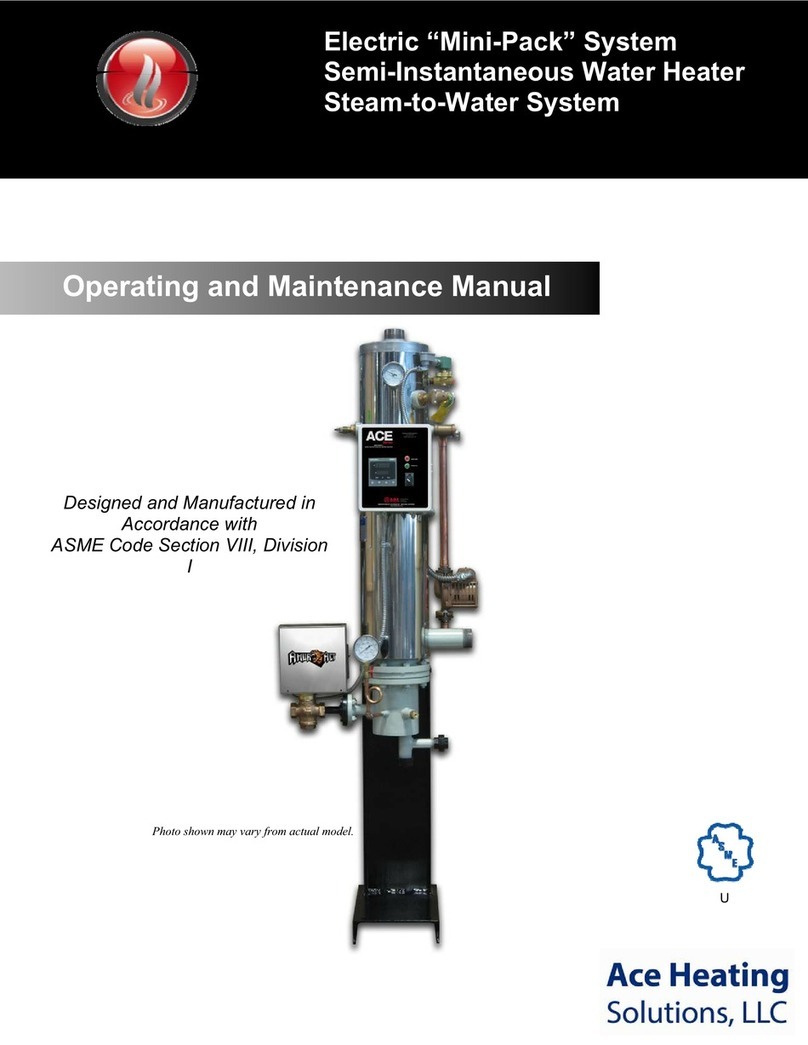
Photo shown may vary from actual model.
Packaged Storage Water Heater
Steam-to-Water System
U


ACE BOILER INC.
Page 2
Table of Contents
Page
3 Operating and Installation Instruction
4 The Packaged Storage Water Heater Name Plate and Model Number
5 The Parts of the Packaged Storage Water Heater
How it works
7 Receiving your Packaged Storage Water Heater
General Installation Instruction
10 Before Start-up
Installation and hook-up
Start-up Instruction
Shut down instruction
Safety features
Operation of storage water heater
13 Trouble-shooting Guide
14 Maintenance Instruction
Removing the tube bundle
Packaged Storage Water Heater component weights
Gasket installation
Tube bundle and bonnet installation
Preventive maintenance
Replacement parts
Material Safety Data Sheet
Contact Us
Warranty
Manufacturers Cut-Sheets (Disclaimer: Some parts may vary from actual model)

ACE BOILER INC.
Page 3
Operating and Installation
Instructions (Pneumatic / Pilot-Operated)
Congratulations on your purchase of a new Ace Boiler, Packaged Storage Water Heater. In this book, we
have included installation and maintenance instructions that, if followed, will provide you with many years
of service from your new unit. Also included are instruction manuals for each of the controls furnished
with the heater. Please read them carefully. They should be helpful in both the installation and service of
this unit. Keep these instructions with the heater for future reference.
The Ace Packaged Storage Water Heater is of rugged construction, yet of simple design. The heater
uses steam (or water) from a boiler to heat domestic hot water in the tank. The storage heater's
temperature control system enables it to control the heated water within the tank at the desired
temperature. This close control is accomplished by placing the temperature control element directly in the
constant flow path of the circulated domestic water. The integral circulator constantly recirculates water
over the heat exchanger.
Lined Packaged Storage Water Heaters feature construction with rust free austenitic stainless fittings and
copper tubes for all domestic water contact surfaces, providing a high quality, low maintenance and an
extremely cost effective domestic water heating package.
The heat exchanger tubes are rolled and flared into a carbon or stainless steel tube sheet. Each storage
heater is constructed and stamped in accordance with Section VIII of the ASME Code, which is stamped
on the vessel nameplate.
Experience in the field has proven that the Ace Packaged Storage Water Heater, if properly applied and
maintained, will give many years of efficient, dependable and economical service.
Ajax Boiler Inc.
February 2006

ACE BOILER INC.
Page 4
The Packaged Storage Water Heater Nameplate
And Model Number
The Packaged Storage Water Heater Nameplate
The following illustration is an accurate depiction of the nameplate found on the Packaged Storage Water
Heater.
A. NB or serial number
B. Shell pressure
C. Shell temperature
D. Tube pressure
E. Tube temperature
F. Min. Atmospheric Pressure
G. Atmospheric temperature
H. Serial number
I. Year built
J. Model number
K. Capacity
L. Square feet
M. Job number
The Packaged Storage Water Heater Model Number
PH G 72 10 - G – 2. 1066 S A
P = Packaged
H = Type (H = Horizontal, V = Vertical)
G = Tank Design Pressure (G = 125, J = 150)
72 = Tank Diameter
10 = Shell Length in feet
G = Lining Code (G = glass, K = prekrete, U = unlined, C = cement, X = special, S = stainless)
2. = # of Passes
1066 = Coil model number (10 = diameter, 66 = length
S = Heating medium (S = steam, W = water, H = hi-temp water)
A = Valve control (A = pneumatic, S = self-contained, P = pilot-operated)
Ace Heating Solutions, LLC

ACE BOILER INC.
Page 5
B
Drain
Recirculation
Line
Boiler Water
Inlet
Manhole
12" x 16"
(42" Dia.
& larger)
Optional
1-1/2"
Insulation &
Metal Jacket
Relief Valve
Pneumatic
Control
B.W.
Temperature
Gauges (2) -
In & Out
ACE TEMP
Control
System with
Sensors
Circulator
Pump
Cold Water
Inlet
Press. &
Temp Gauge
Plug Valve &
Piping
Strainer
Hot Water
Outlet
Anode
(for glass
lined tanks) Lifting Lugs
Boiler Water
Return
To Air Supply
Control
Valve
Tube
Bundle
Nozzle
Removable
Heating Section
Tube
Bundle
Support
Drain
Storage Section
Control Valve
Press. &
Temp Gauge
Circulator
Pump
Pneumatic
Control
Boiler Water
Supply Inlet
Cold Water
Inlet
Optional
1-1/2"
Insulation
22 Gauge
Jacket
Relief Valve
Bronze Plug
Valve &
Piping
To Air Supply
Recirculation
Line Removable
Heating
Section
ACE TEMP
Control
System w/
Sensor
Strainer
Tube
Support
(for longer bundles)
B.W.
Temperature
Gauges (2) -
In & Out
Boiler Water
Return
Hot Water
Outlet
Manhole
12" x 16"
(42" Dia.
& larger)
Lifting
Lug
Tube
Bundle
Nozzle
Anode
(for glass
lined tanks)
Lifting
Lug
Water to Water
Pneumatic
Horizontal
Water to Water
Pneumatic
Vertical
Drain
Storage Section
Control Valve
Press. &
Temp Gauge
Circulator
Pump
Boiler Water
Supply Inlet
Hot Water
Outlet
Cold Water
Inlet
Manhole
12" x 16"
(42" Dia.
& larger)
Optional
1-1/2"
Insulation
22 Gauge
Jacket
Relief Valve
Bronze Plug
Valve &
Piping
Recirculation
Line Removable
Heating
Section
Lifting
Lug
Tube
Bundle
Nozzle
ACE TEMP
Control
System w/
Sensor
Strainer
Anode
(for glass
lined tanks)
Tube
Support
(for longer bundles)
B.W.
Temperature
Gauges (2) -
In & Out
Boiler Water
Return
Lifting
Lug
Water to Water
Self-Operating
Horizontal
Water to Water
Self-Operating
Vertical
B
Drain
Recirculation
Line
Optional
1-1/2"
Insulation &
Metal Jacket
Relief Valve
B.W.
Temperature
Gauges (2) -
In & Out
ACE TEMP
Control
System with
Sensor
Circulator
Pump
Cold Water
Inlet
Press. &
Temp Gauge
Plug Valve &
Piping
Strainer
Anode
(for glass
lined tanks)
Boiler Water
Return
Lifting Lugs
Hot Water
Outlet
Boiler Water
Inlet
Control Valve
Tube
Bundle
Nozzle
Tube
Bundle
Support
Removable
Heating Section
Manhole
12" x 16"
( 42" Dia.
& larger )
Parts of the Packaged Storage
Water Heater (Pneumatic / Self-Contained)
Diagram may vary from actual model

ACE BOILER INC.
Page 6
How It Works!
The Packaged Storage Water Heater is designed to heat domestic hot water using existing plant steam or
hot water. The control valve regulates the heating medium through the tube bundle.
As there is a demand for domestic hot water, the temperature control bulb will sense the drop in water
temperature. The temperature bulb sends a signal to the control valve to open and allow steam or hot
boiler water into the heat exchanger tube bundle. As the steam or hot water passes through the tubes,
the domestic water in the tank is heated.
The circulator constantly circulates the domestic water over the heat exchanger coil, contributing to the
heat transfer.

ACE BOILER INC.
Page 7
Receiving Your Packaged Storage Water Heater
Check Equipment Received. Inspect the unit for any shipping damage. Make sure you have received
all loose parts, such as listed on the “Bill of Lading”. Larger strainers and valves, usually 2-1/2” and
above, are shipped loose. Note any damages or shortages on the bill of lading prior to signing it. If the
unit is received damaged or missing parts, it is your responsibility to notify the shipping company and file
a freight claim. Ace Boiler cannot send replacement parts for freight damaged or missing equipment as
warranty items. Permission to return goods must be received from the factory prior to shipping. Goods
returned without a Returned Goods Authorization number will not be accepted. Purchased parts are
subject to replacement only under the manufacturer’s warranty. The warranty does not include the cost
for labor, removal, or installation of the warranted part.
General Installation Instruction
NOTE: All electrical and piping installation should only be accomplished by qualified
personnel following all applicable local, and state codes required for their installation.
Code Requirements: It is very important that your installation comply with all
federal, state and local codes as well as meet good industry practices as shown in publications issued by
ASME, AGA, UL, ASHRAE, ABMA, etc.
Placement: The storage heater was either fabricated as a vertical or horizontal unit. It should be
installed on a solid foundation, preferably a concrete pad. Provide adequate clearance for normal
inspection and maintenance purposes and allow tube pull clearance to remove the exchanger for
servicing. A minimum clearance of 24” is recommended from all accessories for ease of maintenance.
Make sure the heater is level, from side to side and front to back. Use metal shims if necessary.
Piping: All piping to and from the heater must be provided with adequate supports and expansion
compensation so that pipe stresses are not transmitted to the unit. The relief valve and the double-safety
solenoid valve, if supplied, should be piped to a safe drain.
Stud Nuts: During shipment, the bonnet and shell flange nuts may loosen and should be re-tightened
before start-up. Tighten these nuts to the torques specified later in this manual. After the unit has been
in operation for a few days, check and retighten. Note: Bolting is independent on the bonnet and shell-
side flanges through the use of a threaded tube sheet flange(s). Therefore, stud bolt nuts must be re-
tightened on both sides. See Figure 1.1 for single wall bolting arrangement and Figure 1.2 for double wall
bolting arrangement.

ACE BOILER INC.
Page 8
Torque’s: The following are recommended bolt torque requirements
Bolt Size Min Torque Max Torque
1/2" 45 ft-lbf. 60 ft-lbf.
5/8" 90 ft-lbf. 120 ft-lbf.
3/4" 150 ft-lbf. 200 ft-lbf.
7/8" 240 ft-lbf. 320 ft-lbf.
1" 368 ft-lbf. 490 ft-lbf.
1 1/8" 533 ft-lbf. 710 ft-lbf.
1 1/4" 750 ft-lbf. 1000 ft-lbf.
1 1/2" 1200 ft-lbf. 1600 ft-lbf.
Notes:
* Spray each stud bolt and nut generously with penetrating oil before re-torque.
** Gasket thickness before compression. All partition gaskets are in width before compression. All gaskets
expand twice their width after compression.
*** These are recommended torque values. Stud bolts must not be stressed above 60% of their yield strength.
Stud bolt torque (T) & Bolt diameter (Y)
Gap between flanges
approx. (X) after torque
Figure 1.2
Shell flange to bonnet flange joint –
DW Tube Bundle
360º Leak detection area
Figure 1.1
Shell flange to bonnet flange joint –
SW Tube Bundle

ACE BOILER INC.
Page 9
Water Connections: Pipe cold domestic water in, hot out, and drain according to the cover drawing.
Steam Piping: Check the steam supply pressure. The steam supply pressure should not exceed the
maximum pressure specified on the control valve, relief valve, or vessel nameplate.
Condensate: The condensate outlet of the steam trap is to be connected to condensate return line.
Relief Valve: The relief valve discharge must be piped to a floor drain to eliminate the potential of
scalding burns. The drain line must be the same size as the relief valve outlet and have a downward
slope to insure proper drainage. The drain line termination should be visible to see discharge. Check the
relief valve nameplate. The unit's operating pressure cannot exceed that listed on the relief valve.
Electrical: Standard units only require power to the circulation pump. If optional electrical equipment
such as a safety solenoid is included, power is to be wired according to the wiring diagram. Verify the
electrical supply using a voltmeter. The voltage tie-in leads are indicated on the wiring diagram. This unit
contains sensitive control components and should be protected by a suitable commercial grade surge
protection device. The Packaged Storage Water Heater must be installed in accordance with the National
Electric Code and in accordance with all state and local codes.
Water Treatment: We, the manufacturer of your Packaged Storage Water Heater, wish to call to
your attention the necessity for a sound approach to proper water treatment. The Packaged Storage
Water Heater uses boiler steam or hot water as its heating medium. On steam systems, boiler makeup
water continuously introduces contaminants; scale forming solids, corrosive minerals and oxygen, which
can cause corrosion or scale formation inside the Packaged Storage Water Heater tube bundle.
Whenever appreciable amounts of raw makeup water are continuously added to your system, we
recommend that the problem be brought to the attention of a qualified water consultant. Proper treatment
will insure longer product life and reduced maintenance.

ACE BOILER INC.
Page 10
Before Start-up
Installation and Hook-up
1 Place tank in location desired, and level tank carefully to insure levelness of heating coil loops
which are installed in the tank. Provide sufficient clearance in front to permit removal of the tube
bundle.
2 Remove temporary pipe plugs and caps from all tapping and discard. Inspect and clean all
openings.
3 Install cold water supply line to bottom connection marked Cold Inlet on drawing. Install a gate
valve and union for supply shut-off as desired.
4 Install hot water supply line to service from top connection marked Hot Outlet on drawing. A
valve at this connection is desirable but not necessary.
5 Install relief valve(s) in top connection of tank, and pipe relief valve outlet(s) to a safe drain area.
6 Hook warm return circulation line to tee provided near pump if return line is to be used. A check
and gate valve should be installed in return line, with flow through check valve toward generator.
7 Hook hot water or steam supply to upper coil supply line. A gate valve should be installed.
8 Hook up hot water return to boiler, or for steam, hook up condensate return to boiler condensate
return tank. Pipe size to correspond to opening size provided. This pipe must run horizontal, or
pitch gradually to condensate tank, with condensate level to be below tube or coil level in
generator.
9 CAUTION: Do not introduce steam or water without having the safety relief valves installed on
tank, as excessive pressure may result, with damage to tank or heating coil.
10 Water circulating pump should be wired to run continuously.
11 Storage water heaters are hydrostatically tested in accordance with code requirements, and are
certified as satisfactory by inspection agencies agree upon by manufacturer and purchaser.
However, normal yielding of gaskets will occur in the interval between hydrostatic testing in the
manufacturer’s shop and installation at the job site. Therefore, all external bolted joints should
be properly retightened after installation and again after the exchanger has been heated, to
prevent leaks and blowing out of gaskets. Follow industry recognized flange bolt tightening
practices
12 In all installations, care should be taken to eliminate or minimize transmission of fluid pulsations
and mechanical vibrations to the tank or tube bundle.
13 Install anodes (shipped loose) on all glass lined tanks. Failure to install anodes will void
warranty.

ACE BOILER INC.
Page 11
Start-up Instruction
1 It is assumed that installation is complete and that all connections have been made, including:
electrical, steam, domestic water, instrument air, vents, drains and safety valve discharge lines.
2 If an optional control box is included, make sure the power switch is in the “off” position.
3 Set the temperature controller on the pilot to a minimal water temperature output, following
instruction in the technical data sheet provided (factory does not present).
4 If option is provided, adjust the high limit control 12º to 15ºF higher than the desired hot water
outlet temperature.
5 Ensure the shut-off valve on the bonnet side (heating medium side) is closed.
6 Slowly fill the packaged storage water heater with domestic water, making sure all air is
evacuated prior to start-up.
7 Plant steam, used as the heating medium, is controlled by a pilot operated control valve. The
pilot utilizes upstream steam pressure to modulate the control valve based on the temperature of
the thermostatic element. Steady upstream supply steam pressure is imperative to the
temperature control.
8 If an optional control panel is included, turn the control panel switch to “On” position (the manual
steam supply valve should be closed). The green light should come on. At the same time, it will
energize the solenoid to open the pilot control line to the valve. Make sure the circulator pump is
running. (Please refer to the pump instruction manual for details.)
9 Manually open the main steam shut-off valve upstream of the control valve and SLOWLY allow
steam to pass through the control valve. Continue until the shut-off valve is 100% open.
10 The packaged storage water heater will now function automatically, reacting according to
demand fluctuations and will stabilize once limits are met.
11 Observe the entire system over a period of large demand fluctuations and readjust as
necessary by adjusting the pilot control wheel. (See enclosed technical instruction on the
temperature pilot).
12 After initial start-up, it is recommended to inspect the upstream strainer for any dirt or debris
that may have accumulated. This should be done in accordance with company recommended
safety procedures.
Shut Down Instructions
1 Close the main upstream shut-off valve to the packaged storage water heater.
2 De-energize all electrical power to the packaged storage water heater.
3 Allow the unit to cool down (Approximately 24 hours).
4 Close domestic water inlet and outlet shut-off valves.
Safety Features
1 The pilot-operated steam control valve is designed to fail closed in the event of an over-temp
condition or power failure.
2 The relief valve is designed to relieve the pressure in the packaged storage water heater in the
event the system pressure exceeds its set point.
3 The double safety solenoid (Optional) is designed to dump the domestic water in the shell in the
event that the water temperature exceeds the set point on the high limit control (Optional).

ACE BOILER INC.
Page 12
Operation of Storage Water Heater
1 The entire system should be clean before starting operation to prevent plugging of tubes. Under
some conditions, the use of strainers in the pipe may be required.
2 When placing unit in operation, open a vent and start to circulate the cold medium only. Be sure
that the passages in the tank are entirely filled with cold fluid before closing the vents. The hot
medium should be introduced gradually until all passages are filled with liquid or steam. Then
close vents and slowly bring the unit up to temperature. (Relief valve or faucet may be used as a
vent.)
3 Start operation gradually. Do not admit hot fluid to the unit suddenly when empty or cold. Do not
stock unit with cold fluid when unit is hot.
4 Start the circulating pump (to run constantly). Note: Do not run the circulating pump without
water in the system, as this may damage the pump.
5 Slowly turn on manual hot water or steam supply valve to coil and check for possible leaks in
piping, flanges and gaskets.
6 Make sure the gate valve on auxiliary air vent and steam trap is open (if provided on the
equipment).
7 Return line out of coil should start to warm up quickly, indicating boiler water or steam is heating
tank.
8 The automatic hot water or steam control valve may require adjustment to set to desired tank
temperature. If the tank does not get hot enough, the steam valve should be adjusted (screwed
in) to a higher number. If the tank temperature is too hot, screwing out to a lower number will be
necessary. See valve catalog for further instructions regarding maintenance and adjustments of
the control valve. Once the temperature regulator is set, it will maintain a constant tank
temperature by modulating the hot water or steam supply to any demand or temperature change
of the water stored in the tank, up to the capacity of the coil to produce hot water.
9 Ordinarily, once the temperature regulator is set properly, and the strainers and valves are clean
and operating properly, no further attention is needed for several months of operation.
10 Do not operate equipment under conditions in excess of those specified on nameplate.
11 In shutting down, flow of hot medium should be shut off first. If it is necessary to stop
circulation of cooling medium, the circulation of hot medium should also be stopped, by
bypassing or otherwise.
12 When shutting down the system, all fluids should be drained to minimize the possibility of
freezing and corrosion. To guard against water hammer, condensate should be drained from
steam heaters and similar apparatus when starting up or when shutting down. To minimize
water retention after draining the tube side of water cooled exchangers should be blown out
with air.

ACE BOILER INC.
Page 13
Trouble-shooting Guide
a Water temperature too high
1 Check the setting of the pilot controller and adjust the hand wheel as necessary.
2 Confirm steam supply pressure to the valve does not exceed that specified in the List of
Materials.
3 Bad sensing element.
4 Check bleed port for proper orifice fitting (No. 4A) and/or plugging.
5 Check for dirt under valve seats.
6 Valve disc is worn.
b Banging or pinging
1 Check steam traps for proper operation.
2 Check for proper condensate drainage. Clean out all dirt and debris.
3 Check for back pressure in the condensate line.
c Erratic temperature control
1 Make sure the circulator pump is pumping.
2 Check for proper direction of the circulator pump. The pump should be flowing from the tank
to the nozzle neck.
3 Check steam traps for debris and proper operation.
4 Confirm steam supply pressure to the valve is steady and agrees with that specified in the
List of Materials.
5 The hand wheel on the pilot controller needs adjustment.
6 Check the control temperature bulb for exterior scale or build up and clean if necessary.
7 Check for debris in pilot and valve.
d Poor recovery
1 Check the setting of the pilot controller and adjust the hand wheel as necessary.
2 Confirm steam supply pressure to the control valve meets that specified in the list of
materials. Check for a clogged strainer, a partially closed supply valve or other obstructions.
3 Make sure the packaged storage water heater is not trying to supply more hot water than it
was designed for. (See performance listed in List of Materials).
4 Check to make sure that the proper bleed port orifice fitting (No. 4A) is on the unit. (See the
pilot Technical Data Sheets enclosed).
5 Check for plugging of the control pipe and the orifice in the No. 5A restriction flow elbow.
6 Check the steam trap for any foreign matter and functionality.
7 Main valve diaphragm may be broken. Test with air or water before dismantling.
8 Shut unit down, remove bonnet and coil. Inspect for scale and fouling, which restrict heat
transfer. Clean with an approved chemical treatment
e Control valve not closing
1 Check the setting of the pilot controller and adjust the hand wheel as necessary.
2 Confirm steam supply pressure to the valve does hot exceed that specified in the List of
Materials.
3 Check bleed port No. 4A for proper orifice fitting and/or foreign matter.
4 Check the thermostatic sensing element for kinks & operability.
5 Main valve or pilot may be held open by foreign debris.
6 Valve disc is worn.

ACE BOILER INC.
Page 14
Maintenance Instruction
The following service is recommended for proper and safe use of this equipment monthly or more often.
1 Open relief valve(s) momentarily by lifting try lever to be sure valve(s) will open and are operational.
2 Check tank pressure gauge. Pressure of system should not exceed pressure rating on tank or relief
valve name plate.
3 Check steam pressure gauge to confirm steam supply is adequate. (Gauge will not show pressure
except while system is heating, as pressure connection down stream of automatic steam valve.)
Check tank thermometer, preferably when hot water demand is low, to verify that the steam valve is
functioning to control temperature of tank within desired limits.
NOTE: Tank is supplied with temperature or pressure relief valve(s) which will open automatically
should the water temperature exceed 2100ºF or rated relief valve pressure.
4 Open drain valve at rear of tank for about ½ minute, and flush to drain to remove any mud or sludge
from circulation line and bottom of tank.
5 Oil pump motor with 6 to 10 drops of S.A.E. 30 non-detergent motor oil, in each of 2 oil cups on
motor.
6 Oil pump bearing housing with 1 or 2 teaspoons of oil of S.A.E. 30 motor oil as above, in pump baring
oil cup. CAUTION: Do not over-oil motor bearings, as this will result in rapid dust collection and
overheating of motor.
7 Clean pump motor air intake and exhaust slots with a soft brush or vacuum cleaner.
8 Inspect anodes on glass lined tanks. Replace anodes if 5/8” or less in diameter. Failure to maintain
anodes will void warranty. Keep all records of anode inspection and replacement for warranty
guarantee.
Yearly Maintenance
A thorough cleaning of interior of tank and exterior of tank coil surfaces should be performed as required,
or after the first year’s service, to establish a basis for future need of services.
TO CLEAN TANK, PROCEED AS FOLLOWS:
1 Shut off steam or boiler water supply to tank coil.
2 Shut off cold water supply to bottom of tank.
3 Shut off hot water supply valve at top of tank if one is used.
4 Turn off electric supply to circulating pump.
5 Open drain valve at bottom rear of tank and relieve pressure on tank.
6 Open relief valve on top of tank, or remove it by unscrewing valve, to allow air to enter tank so water
will drain freely, and drain tank fully.
7 Remove one manhole bolt and crab assembly, and loosen other bolt about ½”
8 With a block of wood about ½” long and a #2 hammer, hold the manhole cover and tap to break the
gasket loose, and dislodge cover from manhole ring. This cover may now be pushed into the tank
and remove to outside, by rotating the manhole cover after removing the crab from bolt, and using the
bolt for a handle to prevent dropping the cover within tank. The interior of tank may be viewed thru
the open manhole. If the tank is cement lined, any sludge, mud, or other deposits may be washed
out thru the drain, and lining scrubbed off with a coarse brush or wire brush. The copper tank coil
should be inspected for buildup of sediment or lime deposits on the tubes.

ACE BOILER INC.
Page 15
9 A new manhole gasket will probably be required when replacing the manhole cover. To facilitate
replacement of the manhole gasket, and cover, it will be helpful to tape the gasket to the cover with 4
pieces of adhesive tape, to avoid slippage of gasket from cover. Gasket and cover should be
centered carefully before tightening bolts, to avoid gasket leaking or blowing out.
10 Oil and tighten bolts moderately, refill tank and allow pressure to build up on tank before attempting
to fully tighten bolts, as the water pressure will help seal the gasket.
Maintenance of Tube Bundle
Inspection of Unit
Frequently and at regular intervals, observe interior
and exterior conditions of all tubes and keep them
clean. Tube cleaning negligence may result in
complete stoppage of flow through some tube, with
consequent overheating of these tubes and
compared to surrounding tubes, resulting in severe
expansion strains and leaking tube joints.
Indication of Fouling
Tube bundles subject to fouling scaling should be
cleaned periodically. A light sludge or scale coating
on the tube greatly reduces its effectiveness. A
marked increase in pressure drop and/or reduction
in performance usually indicate cleaning is
necessary. (Assuming the unit has been checked
for air or vapor binding and this has been found not
to be the cause.) Since the difficulty of cleaning
increases rapidly as the scale thickens or deposit
increases, the intervals between cleaning should
not be excessive.
Access to Tubes
To clean or inspect inside of tubes, remove the cap.
CAUTION: Do not loosen heads until you are sure
all pressure is off equipment, and the unit is
drained.
Tube Bundle Removal
When removing the tube bundle from the tank for
inspection or cleaning, care should be exercised to
see it is not damage by improper handling. Tube
bundles are often of great weight, yet the tubes are
small and of relatively thin metal. The bundle,
therefore, should rest on parts designed to carry it,
i.e., on the tube sheets, baffles, or support plates.
For withdrawing tube bundles from the tank, the
use of steel eye bolts which are screwed into the
tube sheet is recommended for the attachment of
the cable or other pulling devices. Steel rods
inserted through the tubes, and bolted to a bearing
plate at the end of the bundle may also be used.
When steel cables are used for lifting vertical tube
bundles, the cable should be attached to the lifting
eyes where possible. An alternate method is to use
steel rods as described above. If the tube
bundle has been in service for a considerable
length of time without being removed, it may be
necessary to use a hydraulic jack on the tube
sheet to get it started. A good-sized steel
bearing plate should be inserted between jack
and tube sheet and tube ends should be
protected by means of a filler board.
Handling Tube Bundles Outside Shell
Do not handle tube bundles with hooks or other
tools, which might damage tubes. Bundles
should be moved out on cradles or skids.
Horizontal tube bundles should be lifted by
means of suitable slings. Baffles can be easily
bent and damaged by dragging a bundle over a
rough surface. Since the proper functioning of
the apparatus depends upon a close fit between
the outside of the baffle and the inside of the
shell, any damage to the baffles must be
carefully avoided.
Cleaning Procedures
1 Do not attempt to clean tubes by blowing
steam through individual tubes. This over
heats the tube and results in the same
expansion strains and leaks as for plugged
tubes.
2 Do not blow out tube bundle with air when
fluids normally handled are inflammable.
3 In cleaning a tube bundle, tube should not
be hammered on with any metallic tools. In
case it is necessary to use a scraper, care
should be exercised to see that the scraper
is not sharp enough to cut the metal of the
tubes.
Tube Rolling
To tighten a loose tube joint, use a suitable roller
type tube expander. Do not roll tubes that are not
leaking, as it needlessly thins and work hardens
the tube wall.

AJAX BOILER INC. - ACE BOILER INC.
FACTORY LIMITED WARRANTY POLICY
The Ajax Boiler Factory limited warranty provides assurance that all products are free from manufacuteres defects at the time of
shipment and meet specifications and performance described in the product literature.
It is important to understand the difference between a factory warranty and an installed warranty. There are many factors that can
occur to the products after they are shipped that the company has no control over and can not fully verify. These includes:
1. Hidden damage during the shipping.
2. Handling damage.
3. Damage during storage.
4. Installation conditions.
5. Other unknown variables in the system design: maintenance, pulsation and vibrations.
The installed warranty is the responsibility of the architech, specifying engineer, contractor and/or owner who jointly have control over
the application, installation, location, operating and maintenance conditions.
The Ajax Boiler Inc. warranty excludes extended liabilities. Extended liability typically occurs when products are installed without proper
drainage, flooding containment or when safety devices are not tested and repaired or replaced when needed.
Product problems are often caused by the condition of the water, the lack of water treatment and/or the improper treatment of
the water, insufficient combustion air, improper draft conditions, bolts not re-tightened, pipes not flushed and cleaned of oil, metal
chips, rags, vibration and pulsation etc. These are installation, operating and/or maintenance conditions that are beyond the seller’s
responsibility and are not covered by the factory warranty, but may be covered by the installer’s warranty.
The factory warranty covering company products is based upon extensive product development and testing. Combustion products
under go certification testing and approvals to Underwriters Laboratory (UL) standards. Auditing of the production of combustion
products is conducted by a nationally recognized testing laboratory.
Pressure vessel products are designed and manufactured to American Society of Mechanical Engineering (ASME) and National Board
(NB) Design standards. Design reviews, factory product manufacturing quality inspections and testing are carried out by a third party
National Board authorized inspection agency.
Ajax Boiler Inc. products have proven themselves in service for over 85 years which indicates that the company products perform
exceedingly well when normal installation, operating and maintenance conditions exist.
The following is a review from the terms and conditions of sale. Also included in paragraph two, below, is the Ajax Boiler Inc. non-
conformance policy.
1. Ajax Boiler Inc. warrants its products against defective material and/or workmanship only. The warranty does not apply to
operational failures, electrical failures, gasket leaks, and/or other malfunctions caused by improper application, installation
and/or maintenance.
2. It is the buyer’s responsibility to inspect and accept the product, when received, as conforming to their purchase order,
specifications and approved drawings. All claims for non-conformance, errors, shortages, etc. must be made within 10
days after receipt of the shipment.
3. Ajax Boiler Inc. do not provide a warranty or guarantee, express or implied, in any manner, form, usage of trade, merchant
-ability or fitness which extend beyond the product description and quotation.
4. Ajax Boiler Inc. liability is limited to the factory repair or replacement of warranty failures, or non-conformance, upon the
return of the product to the factory.
5. Ajax Boiler Inc. is not liable for any direct or consequential damages.
6. The Ajax Boiler Inc. warranty is based upon section 23161(2) of the uniform commercial code and is printed in the terms
and conditions of sale which is referenced in every quotation, on the back of sales order acknowledgements and invoices.
It is legally correct and is an industry standard policy.
February-2007
Ace Heating Solutions, LLC
November 2014 ace
Ace
The Ace Heating Solutions, LLC warranty excludes extended liabilities. Extended liability typically occurs when products are
installed without proper drainage, flooding containment or when safety devices are not tested and repaired or replaced when
needed.
A
ce Heating Solutions, LLC products have proven themselves in service for over 85 years which indicates that the company
products perform exceedingly well when normal installation, operating and maintenance conditions exist.
The Ace Factory limited warranty provides assurance that all products are free from manufacteres defects at the time of
shipment and meet specifications and performance described in the product literature.
The following is a review from the terms and conditions of sale. Also included in paragraph two, below, is the Ace Heating
Solutions, LLC nonconformance policy.
1. Ace Heating Solutions, LLC warrants its products against defective material and/or workmanship only. The warranty does not
apply to operational failures, electrical failures, gasket leaks, and/or other malfunctions caused by improper application, installation
and/or maintenance.
2. It is the buyer’s responsibility to inspect and accept the product, when received, as conforming to their purchase order,
specifications and approved drawings. All claims for non-conformance, errors, shortages, etc. must be made within 10
days after receipt of the shipment.
3. Ace Heating Solutions, LLC do not provide a warranty or guarantee, express or implied, in any manner, form, usage of trade,
merchantability or fitness which extend beyond the product description and quotation.
4. Ace Heating Solutions, LLC liability is limited to the factory repair or replacement of warranty failures, or non-conformance, upon
the return of the product to the factory.
5. Ace Heating Solutions, LLC is not liable for any direct or consequential damages.
6. Ace Heating Solutions, LLC warranty is based upon section 23161(2) of the uniform commercial code and is printed in the terms
and conditions of sale which is referenced in every quotation, on the back of sales order acknowledgements and invoices.
It is legally correct and is an industry standard policy.

AJAX BOILER INC. - ACE BOILER INC.
LIMITED
WARRANTY
Ajax Boiler Inc. provides a limited warranty on its products against defective material and/or workmanship only. This
limited warranty is not applicable to operational failures, electrical failures, gasket leaks, wear or malfunctions caused by
improper application, installation, and/or maintenance.
Product Period - The following Limited Warranty period are from date of shipment:
Boiler Pressure Vessels: One year.
Carbon Steel Tank and Heat Exchanger Pressure Vessels: One year.
Stainless Steel Tanks: Three years.
Boiler Copper Fin Coils: Three years.
Single-wall or Double-wall Tank/Exchanger Coils: One year.
Single-wall or Double-wall Mini-Packs™: One year.
Atlas Series Condensing Boiler: One year.
Linings: (Pro-rated Warranty)
In Section VIII Tanks: Glass 30" dia. and above (Five years).
Glass 24" dia. and under (One year).
Cement (Five years).
Pre-Krete (Ten years).
In Section IV Tanks: Glass (One year).
Controls:Components manufactured by other than Ajax Boiler Inc. such as controls, instruments, forced draft
burner, etc., provided with the boilers and packaged products are not covered by the Ajax Boiler Inc.
Warranty. However, Ajax Boiler Inc. extends to the customer the same warranty provided by the
manufacturer to Ajax Boiler Inc. The customer shall receive the full benefits of adjustments made to
Ajax Boiler Inc. by the manufacturer.
Any claim for adjustment under this limited warranty must be made within the warranty period. Ajax Boiler Inc.’s liability shall
be limited to factory repair or, at Ajax Boiler Inc.’s option, replacement of all parts which, upon test and examination by Ajax
Boiler Inc., prove to be defective material and/or workmanship and within the above limited warranty. If required by Ajax
Boiler Inc., parts which are claimed to be defective must be promptly delivered to the Ajax Boiler Inc. facility, transportation
charges prepaid. This warranty does not cover the cost of labor, removal, or installation of the warranted item during the
limited period.
This warranty is limited to the above and applies only for the period set forth. Ajax Boiler Inc. will not be liable for any loss
damage, direct, incidental or consequential damages of any kind, whether based upon warranty, contract, negligence or
strict liability and arising in connection with the sale, use or repair of the products. Ajax Boiler Inc.’s maximum liability shall
exceed the contract price for the product’s merchantability or fitness for any particular purpose and in no event shall be held
responsible for any consequential damages.
For complete Limited Warranty conditions see Section G and H under terms and condition of sale.
Ajax Boiler Inc., also doing business as Ace Boiler Inc., is referred to herein as Ajax Boiler Inc.
2701 South Harbor Blvd.
Santa Ana, California 92704
United States
Tel. (714) 437-9050
Fax (714) 437-9060
http://www.ajaxboiler.com
mail@ajaxboiler.com
February-2007
ACE Heating Solutions, LLC
2701 S. HARBOR BLVD. • SANTA ANA, CA 92704
PHONE: (714) 540-2230 • FAX: (714) 540-2239
www.aceheatingllc.com
Ace Heating Solutions, LLC
November 2014 ace
A
ce Heating Solutions, LLC provides a limited warranty on its products against defective material and/or workmanship
only. This limited warranty is not applicable to operational failures, electrical failures, gasket leaks, wear or malfunctions
caused by improper application, installation, and/or maintenance.
Product Period - The following Limited Warranty period are from date of shipment:
Boiler Pressure Vessels: One year
Carbon Steel Tank and Heat Exchanger Pressure Vessels: One year.
Stainless Steel Tanks: Three years.
Boiler Copper Fin Coils: Three years.
Single-wall or Double-wall Tank/Exchanger Coils: One year.
Single-wall or Double-wall Mini-Packs™: One year.
A
tlas Series Condensing Boiler: One year.
Linings: (Pro-rated Warranty)
In Section VIII Tanks: Glass 30" dia. and above (Five years).
Glass 24" dia. and under (One year).
Cement (Five years).
Pre-Krete (Ten years).
In Section IV Tanks: Glass (One year).
Controls: Components manufactured by other than Ace Heating Solutions, LLC such as controls, instruments, forced
draft burner, etc., provided with the boilers and packaged products are not covered by the Ace Heating Solutions,
Warranty. However, Ace Heating Solutions, LLC extends to the customer the same warranty provided by the
manufacturer to Ace Heating Solutions, LLC. The customer shall receive the full benefi ts of adjustments made to
A
ce Heating Solutions, LLC by the manufacturer.
A
ny claim for adjustment under this limited warranty must be made within the warranty period. Ace Heating Solutions,
LLC’s liability shall be limited to factory repair or, at Ace Heating Solutions, LLC’s option, replacement of all parts which,
upon test and examination by Ace Heating Solutions, LLC, prove to be defective material and/or workmanship and within
the above limited warranty. If required by Ace Heating Solutions, LLC, parts which are claimed to be defective must be
promptly delivered to the Ace Heating Solutions, LLC facility, transportation charges prepaid. This warranty does not cove
r
the cost of labor, removal, or installation of the warranted item during the
limited period. This warranty is limited to the above and applies only for the period set forth. Ace Heating Solutions, LLC
will not be liable for any loss damage, direct, incidental or consequential damages of any kind, whether based upon
warranty, contract, negligence or strict liability and arising in connection with the sale, use or repair of the products. Ajax
Boiler Inc.’s maximum liability shall exceed the contract price for the product’s merchantability or fitness for any particular
purpose and in no event shall be held responsible for any consequential damages.
For complete Limited Warranty conditions see Section G and H under terms and condition of sale.
A
ce Heating Solutions, LLC, also doing business as Ace Heating Solutions, LLC, is referred to herein as Ace Heating
Solutions, LLC

AJAX BOILER INC. - ACE BOILER INC.
WARNING
PRODUCT
SAFETY NOTICE
AJAX BOILER AND WATER HEATER PRODUCTS OPERATE AT HIGH TEMPERATURE AND PRESSURES
• Before using this product, read and understand instructions. Save these instructions for future use.
• Before servicing, to prevent serious burns or injury, the boiler and water heater products must be cooled to less than
80°F (27°C) and the pressure must be 0 psi (0 bar).
• Turn off the electrical power before making electrical connections to prevent electrical shock.
• These products must be placed in a controlled location where untrained or unqualified personnel cannot access the
operating or safety controls, must not be able to come in contact with high temperature or high pressure parts and must
not perform maintenance or demolition work.
• All work performed must be by qualified properly equipped personnel trained in the proper application, installation, and
maintenance or demolition of plumbing, steam, and electrical equipment and/or systems in accordance with all
applicable codes and ordinances.
• Ajax Boilers and Water Heaters are complete package units with safety and operating controls and are constructed with
non ASBESTOS materials. Any replacement gaskets, refractory, insulation, etc used must not contain Asbestos.
• No additional insulation is required on the Boilers and Water Heaters.
• Additions or replacement of insulation on any connecting pipes or accessories to the Boilers and/or Water Heaters must
be of “NON-ASBESTOS” and contain only non-hazardous materials.
• Crystalline Silica, a material known to cause cancer, may be encapsulated in some refractory or insulation materials
and must be handled only by authorized trained personnel. Crystalline Silica as used is encapsulated and is not harm
full in this form. Care must be taken during removal or replacement of refractory or insulation to remove it in bulk
form and avoid generation or inhalation of dust. Removal must be properly performed by trained, qualified and
equipped personnel. This is also true of Asbestos not contained in Ajax products but may be otherwise contained in
replacement materials or parts, in connecting piping or other nearby products.
• All safety and operating controls must be set within the specified operating limits and tested periodically to assure proper
operation. All limit and operating controls must be installed in series on the boiler.
• Connect drain pipes to a safe drain to prevent serious personal injury from relief valve discharge and or from boiler blow
down discharge.
• After installation, check for proper operation of all limit and operating controls before leaving the site.
• Perform scheduled and annual inspections including checking Controls for proper calibration and performance.
Failure to follow these warnings, to allow access by unauthorized persons and the use of non-properly trained and
equipped personnel in the operation, service, modification, removal or demolition of these products or replacement
of parts with non-authorized factory non-asbestos materials could cause damage, personal injury or death.
2701 South Harbor Blvd.
Santa Ana, California 92704
United States
Tel. (714) 437-9050
Fax (714) 437-9060
http://www.ajaxboiler.com
mail@ajaxboiler.com
A
CE
Heating Solutions, LLC
2701 S. H
ARBOR
B
LVD
. • S
ANTA
A
NA
, CA 92704
P
HONE
: (714) 540-2230 • FAX: (714) 540-2239
www.aceheatingllc.com
Ace Heating Solutions, LLC
November 2014 ace
ACE BOILER AND WATER HEATER PRODUCTS OPERATE AT HIGH TEMPERATURE AND PRESSURES
• Before using this product, read and understand instructions. Save these instructions for future use.
• Before servicing, to prevent serious burns or injury, the boiler and water heater products must be cooled to less than
80°F (27°C) and the pressure must be 0 psi (0 bar).
• Turn off the electrical power before making electrical connections to prevent electrical shock.
• These products must be placed in a controlled location where untrained or unqualified personnel cannot access the
operating or safety controls, must not be able to come in contact with high temperature or high pressure parts and must
not perform maintenance or demolition work.
• All work performed must be by qualified properly equipped personnel trained in the proper application, installation, and
maintenance or demolition of plumbing, steam, and electrical equipment and/or systems in accordance with all
applicable codes and ordinances.
• ACE Boilers and Water Heaters are complete package units with safety and operating controls and are constructed with
non ASBESTOS materials. Any replacement gaskets, refractory, insulation, etc used must not contain Asbestos.
• No additional insulation is required on the Boilers and Water Heaters.
• Additions or replacement of insulation on any connecting pipes or accessories to the Boilers and/or Water Heaters must
be of “NON-ASBESTOS” and contain only non-hazardous materials.
• Crystalline Silica, a material known to cause cancer, may be encapsulated in some refractory or insulation materials
and must be handled only by authorized trained personnel. Crystalline Silica as used is encapsulated and is not harm
full in this form. Care must be taken during removal or replacement of refractory or insulation to remove it in bulk
form and avoid generation or inhalation of dust. Removal must be properly performed by trained, qualified and
equipped personnel. This is also true of Asbestos not contained in ACE products but may be otherwise contained in
replacement materials or parts, in connecting piping or other nearby products.
• All safety and operating controls must be set within the specified operating limits and tested periodically to assure proper
operation. All limit and operating controls must be installed in series on the boiler.
• Connect drain pipes to a safe drain to prevent serious personal injury from relief valve discharge and or from boiler blow
down discharge.
• After installation, check for proper operation of all limit and operating controls before leaving the site.
• Perform scheduled and annual inspections including checking Controls for proper calibration and performance.
Failure to follow these warnings, to allow access by unauthorized persons and the use of non-properly trained and
equipped personnel in the operation, service, modification, removal or demolition of these products or replacement
of parts with non-authorized factory non-asbestos materials could cause damage, personal injury or death.

Gasket Replacement
Gasket and gasket surfaces should be thoroughly cleaned and should be free of scratches and other
defects. Gasket should be properly positioned before attempting to retighten bolts. It is recommended
that when a heavy heat exchanger is dismantled for any purpose, it needs to be reassembled with new
gaskets. This will tend to prevent future leaks and/or damage to the gasket-seating surface of the heat
exchanger. Composition gaskets become dried out and brittle so that they do not always provide an
effective seal when re-used, they may provide an imperfect seal or result in deformation and damage to
the gasket contact surface of the exchanger. Follow industry recognized flange bolt tightening practices.
Lifting and Pulling Mechanisms
The following are safe loads for steel rods and eye bolts:
Rods:
Size Tubes Size Rods Safe Load per Rod
5/8” 3/8” 1,000lbs.
3/4" 1/2" 2,000lbs.
1” – larger 5/8” 3,000lbs.
Eye Bolts:
Size Safe Load
3/4" 4,000lbs.
1” 6,000lbs.
1 ¼” 10,100lbs.
1 ½” 15,000lbs.
Cleaning Methods
Provide convenient means for cleaning tube bundle frequently as suggested below:
1 Circulating hot wash oil or light distillate through and over the tube at high velocity will effectively
remove sludge or other similar soft deposits.
2 Circulating hot fresh water may wash out soft salt deposits.
3 Some commercially available cleaning compounds may be used to assist in removing sludge or coke,
provided hot wash oil or water, as described above, does not give satisfactory results.
4 Removal of various scales and foreign material by chemical cleaning is now being quite extensively
practiced. Certain qualified organizations will check the nature of deposits to be removed, furnish
proper acid solutions containing inhibitors, and provide equipment and personnel for a complete
apparatus and piping cleaning job.
5 If none of the above methods are effective for the removal of a hard scale, coke, or other deposits,
mechanical means may be used.
Material Safety Data Sheets
Some of Ajax Boiler products contain materials that have been recognized as posing health risks.
Material Safety Data Sheets for these materials are available from your local Manufacturer’s rep. When
requesting this information, be sure to have the model number and serial number available.
If you do not know who your local Manufacturer’s Rep is, you can find out by logging into the
www.ajaxboiler.com website, and clicking on the Representative tab found in the table of contents.
Ajax Boiler Inc.
2701 S. Harbor Blvd.
Santa Ana, CA 92704
Parts: 714.437.9050
www.ajaxboiler.com
Material Safety Data Sheets
Some of Ace Heating products contain materials that have been recognized as posing health risks.
Material Safety Data Sheets for these materials are available from your local Manufacturer’s rep. When
requesting this information, be sure to have the model number and serial number available.
If you do not know who your local Manufacturer’s Rep is, you can find out by logging into the
www.aceheatingllc.com website, and clicking on the Representative tab found in the table of contents.
Ace Heating Solutions, LLC
2701 S. Harbor Blvd.
Santa Ana, CA 92704
PH: 714.540.2230: FAX: 714.540.2239
www.aceheatingllc.com
This manual suits for next models
1
Table of contents
Other Ace Heating Solutions Water Heater manuals
Popular Water Heater manuals by other brands

Elson
Elson 120zi installation manual

Nibe
Nibe UKV 200 installation instructions

Midea
Midea M2005 Installation and operation guide

clage
clage MDX Series Operating and installation instructions

Buffalo
Buffalo TELE - 0112 704123 installation manual

Automatic Heating
Automatic Heating Firex 34 operating manual