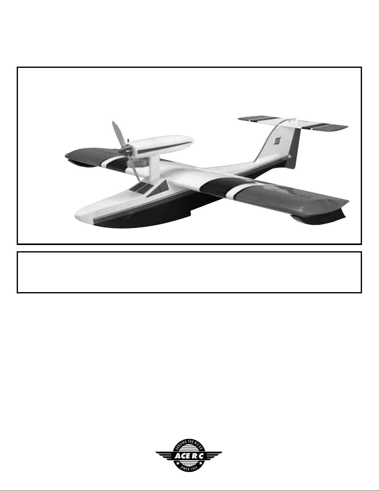
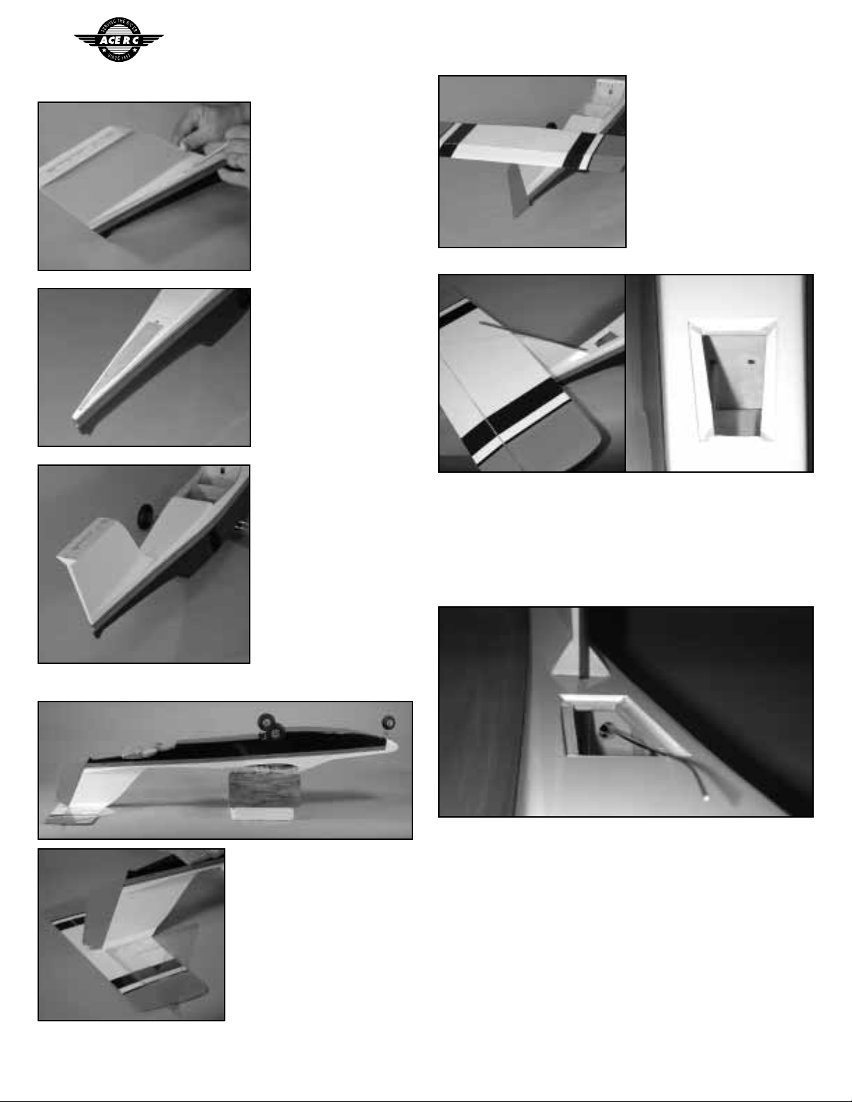
ACE RC Seamaster ACE4527 User manual

1
Ace R/C Seamaster ARF Airplane (ACE4527)
Distributed in North America by Ace Hobby Distributors, Inc. • 116 W 19th ST, Higginsville, MO 64037
Phone: 660-584-7121 • www.acehobby.com • E-mail: service@acehobby.com
Seamaster
Assembly Manual
Wing Span: 59.5”
Wing Area: 725 in2
Length: 54”
Weight: 7 lbs.
Engine: .40-.46 2 cycle
.54-.60 4 cycle
Radio: 4 channel
Specifications:
Warranty
This kit is guaranteed to be free from defects in material and workmanship at the date of purchase.
It does not cover any damage caused by use or modification. The warranty does not extend beyond the prod-
uct itself and is limited only to the original cost of the kit. By the act of building this user-assembled kit, the
user accepts all resulting liability for damage caused by the final product. If the buyer is not
prepared to accept this liability, it can be returned new and unused to the place of purchase for a refund.
20091/JExxxx
Notice: Adult Supervision Required
This is not a toy. Assembly and flying of this product requires adult supervision.
Read through this book completely and become familiar with the assembly and flight of this airplane.
Inspect all parts for completeness and damage. If you encounter any problems, call 660-584-6724 for help.

2
INTRODUCTION
PRE-ASSEMBLY NOTES
Initially introduced to the hobby market in the 1980's, the Seamaster 40 has remained the most recogniz-
able amphibious model airplane in the world. Many thousands of these models have been flown over the
years, so rest assured you have obtained the best flying amphibian on the market.
Although the plane looks bigger, a good .40-.45 two cycle or .54-.60 four cycle flies the plane nicely; don't
be tempted to put a bigger engine on it; the airframe is not stressed for it. Realize the Seamaster is not a pat-
tern ship; it is a mildly aerobatic sport ship designed for pleasing, predictable performance off both land and
water.
Before beginning the assembly read the instructions thoroughly to give an understanding of the sequence
of steps and a general awareness of the recommended assembly procedures.
By following these instructions carefully and referring to the corresponding pictures,the assembly of your
model will be both enjoyable and rewarding. The result will be a well built, easy to assemble A.R.F. model,
which you will be proud to display and also provide you considerable enjoyment.
If you are not an experienced R/C pilot,plan to have a fully competent pilot check your completed model
and help you with your first flights. Even though we have tried to provide you with a very thorough instruc-
tion manual, R/C models are rather complicated and an experienced modeler can quickly check over your
model to help make sure your first flights are successful. Your Seamaster is designed for intermediate to
advanced pilots.
Before you begin, check the entire contents of your kit against the parts list and photos to make sure that
no parts are missing or damaged. This will also help you to become familiar with each component of your
plane. If you find that any of the parts are either missing or damaged,please contact Ace Hobby Distributors,
Inc., Customer Service (660-584-6704) immediately for replacements.
Trial fit each part before gluing it in place. Make sure you are using the correct part and that it fits well
before assembling. No amount of glue can make up for a poor-fitting part.

3
RECOMMENDED TOOLS & MATERIALS
Adhesives:
Instant setting Cyanoacrylate adhesive (thin CA)
Slow setting Cyanoacrylate adhesive (thick CA)
10 Minute Epoxy (fast)
20-30 Minute Epoxy (slow)
Zap-a-dap-a-goo, Shoe-goo or equivalent
Clear silicone seal
Tools:
Model knife,T-Pins
Small screwdrivers, Medium screwdrivers
Scissors
Steel straight edge
Long nose pliers and diagonal cutting pliers
Drill and drill bits
Fine felt tip pen and soft lead pencil
Straight building board
Heat sealing iron
Z-Bend pliers (optional)
R/C System:
4 Channel radio with 4 servos
Engine:
2 cycle: .40 to .46 CID
4 cycle: .50 to .60 CID
Propeller (appropriate for engine type and
preferred performance)
Adhesives - You will need two types of adhesives
for the Seamaster - Epoxy and Instant (cyanoacry-
late) adhesives. We recommend that you purchase
both 5-minute and 30-minute epoxy to cut down on
assembly time, but you can get by with only 30-
minute epoxy if time is not important.You will also
need a small bottle of both “Thick”and “Thin”
instant adhesive. Zap-a-dap-a-goo, Shoe-Goo, or
equivalent will also be needed.
Tools - Model assembly can be much easier if the
proper tools are used.Therefore, we have included
in our checklist to the left, a complete listing of all
the tools we used to assemble our prototype mod-
els. As you will notice, many household tools can be
utilized during construction.
Engine - The Thunder Tiger PRO-46 and F-54S are
the ideal engines for this airplane. These quiet-run-
ning engines are easy to start, require no special
break-in periods, are very easy to maintain and will
last for years.
Radio - A 4-channel radio with four standard servos
is required.

4
PARTS DRAWINGS
Servo Rail (2)
AS6058 Fuselage Set
Front Hatch (1) Rear Hatch (1) Servo Rail Mount (4) Tapping Screw 2x8mm (8)
Fuselage (1)
Aileron Servo Tray (1)
AS6059 Main Wing Set
Main Wing (1)
Torque Rod Horn (2)
Engine Pod (1)
AS6064 Engine Pod Set
Self-Tap Screw 2x8mm (8)
Self-Tap Screw 4x16mm (1)
AS6071 Engine Pylon Set
Self-Tap Screw 3x34mm (2) Servo Tape (1)
Engine Pylon (1)
Tip Float (2)
AS6068 Tip Float Set
Velcro (4)
AS6069 Adjustable Engine Mount
Engine Mount Plate (1)
Beam (2, Left/Right)
Self-Tap Screw 3x15mm (4)
Screw 6/32 x 25mm (4)
Blind Nut (4)
AS6023 Control Horn Set
Back Plate (2)Screw 2x12mm (4) Control Horn (2)
3263 Fuel Tank Set
300 cc Tank (1)
Silicone Tube (1) Clunk (1)
Stopper (1) 90-degree Nipple (1)
Straight Nipple (1)
Cap (1) Spinner (1)
3282B Spinner Set
Self-Tap Screw 3x12mm (2)
Back Plate (1)
AS6066 Wing Bolt Set
Socket Screw 4x40 (2) Blind Nut (2) Washer (2)
Plastic Keel (1)

5
PARTS DRAWINGS
Self-Tap Screw
2x8mm (4)
AS6062 Linkage Set
Inner Nyrod (2)
Music Wire (2)
Self-Tap Screw 4x8mm (1)
Self-Tap Screw 3x12mm (4)
Pushrod Clamp (1)
Allen Wrench (1)
EZ Connect, set screw & nut (2)
Clevis (4) Outer Nyrod (2)
Threaded Stud (4)
AS6060 Horizontal Tail Set
Stabilizer/Elevator (1)
Nyrod Spacer (1)
AS6061 Vertical Tail Set
Vertical Fin/Rudder (1)
CA Hinge (3)
AS6070 Water Rudder Set
Screw 4x16mm (1)
Water Rudder (1)
Locknut 4mm (1)
Right Landing Gear (1)
AS6063 Main Landing Gear Set
Collar (4)
Screw 3x5mm (4) Left Landing Gear (1)
3257 Wheel
Wheel 2 3/4"(2)
3254 Wheel
Wheel 2" (1 / Sold in Pair)
AS6067 Decal
Decal
AS6065 Nose Gear Set
Collar (3)
Nose Gear (1)
Steering Arm (1) Screw 3x5mm (3)
Steering Arm Collar (1) Nose Gear Mount (1)
AS6072 Nose Cone Set
Nose Cone (1)
3152 Aileron Pushrods Set PE0009 Hardware Set
Threaded Rod (2) Clevis (2)

6
WING ASSEMBLY/ENGINE POD ASSEMBLY
The tip floats are attached to the wing with the furnished sticky
backed Velcro. Use a square on both the front and back of each tip
float. Position the tip floats on the outer bay of each wing with the
front of the float about 1/2" back from the leading edge of the wing.
Set the wing aside for now.
Engine Pod Assembly
The firewall and firewall braces should be glued to the engine
pylon. Also, holes for the engine mount, reinforcing screws, fuel lines,
and throttle should be pre-drilled. If any of these holes are not drilled
in your firewall, you will have to drill them accordingly.
Screw the two 4 X 35mm self tapping screws through the firewall
into the pylon to reinforce the joint. It is suggested that you use epoxy
to coat the entire firewall, front and back. This will fuelproof it plus
reinforce the glue joints. If you get epoxy in the holes, wipe it out
while the glue is wet, or drill it out when the glue is set.
Secure the engine mount assembly on the firewall using the four
screws and blind nuts furnished. (Normally, the engine is side-mount-
ed with the cylinder head on the right.)
The ailerons are in place with hinges already in their slots.
Remove any tape that may be holding things in place. Hinge the
ailerons by securing the "CA" hinges in place. Begin by making sure
the CA hinges are in proper position and the ailerons have minimal
gap between them and the trailing edge of the wing. (Have a paper
towel ready in case you have to mop up excess glue.) Hold the wing
up on the leading edge and, working from the bottom of the wing,
carefully put a few drops of THIN CA where each hinge goes into the
wing. It should wick down into the wing. Do the same, working from
the top of the wing. Turn the wing over so it is resting on the trailing
edge and repeat where the hinges go into the ailerons. When done,
you should have applied thin CA to all surfaces of each hinge. After
the glue has "fired",make sure the ailerons are free to move by flexing
back and forth. Also make sure the glue joint is secure by tugging on
the ailerons.
Cut the covering material away from the aileron servo cutout hole.
Put the plywood aileron servo tray in position and mark the outer edges
of the plate on the covering material. Being careful to not cut into the
balsa, remove the covering material where the aileron servo tray will
glue to the wing. Glue the aileron servo tray into position.
Mount the aileron servo in place. Screw the nylon horns onto
the torque rods until the top of the horn is flush with the top of the
threaded portion of the torque rod. Link the servo to the aileron
torque rods using the threaded rods furnished. Use a clevis on the
torque rod (threaded) end and a "Z" bend on the servo arm end (non-
threaded). Adjust for neutral with the servo centered.
Photo 1
Photo 2
Photo 3
Photo 6
Photo 5
Photo 4

7
ENGINE POD ASSEMBLY/FUSELAGE ASSEMBLY
The engine pod is blowmolded plastic. To cut this material, score
a few times with a sharp utility knife. Once a cut-out is made, you can
whittle away the rest or use a Dremel tool with a sanding drum.. Work
carefully. It is easy to cut too much away;it is also easy to cut yourself.
Begin by separating the front from the rear by cutting along the
line indicated. Also make the rectangular cutout in the bottom of the
rear of the pod, extending the cut to the front edge of the part.
Test fit the parts onto the engine mount assembly so both halves
meet in the middle of the firewall.
Position your engine on the engine mount (note that the mount's
beam width is adjustable to accommodate your engine). Locate the
engine on the mount so the front of the prop's thrust washer is 4 1/4"
from the front surface of the firewall. Double check that this set-up
gives you 1/8”-1/4”of spinner clearance from the front of the engine
pod. Mark then drill pilot holes using a 3/32" bit. Mount your engine
using the four M3 X 15mm screws.
NOTE: A bench vise makes a handy holding fixture while you are
working on your engine pylon assembly.
Trim the front engine pod to clear the cylinder head,muffler,nee-
dle valve,and carb. A utility knife and Dremel tool with a sanding drum
makes easy work of this task.
Both the front and rear engine pod are secured with the furnished
2X8mm self tap screws. (Four for the front and four for the rear.) Drill
1/16" pilot holes for the screws.
Remove the front and rear pod halves. The throttle servo is
mounted on the right side of the engine pylon behind the firewall
using servo tape. The throttle linkage consists of a length of music
wire with a“Z”bend on the throttle arm end and an EZ connect on the
servo arm end. The servo cable goes into the slot that is machined in
the rear of the engine pylon.
Assemble the fuel tank as shown. The fuel tank is housed in the
rear engine pod and held in place with lightly wrapped foam rubber.
Fuselage Assembly
To prevent damage, have a piece of foam over your work surface
to rest the hull of the fuselage upon as you work on it. Cut away the
covering film that is over the slot for the engine pylon, leaving 1/4”
excess all along the slot. Cut the film diagonally to each corner and
then use a heat sealing iron to seal the edges along the inside surfaces
of the slot.
Photo 7
Photo 8
Photo 9 Photo 12
Photo 11
Photo 10

8
FUSELAGE ASSEMBLY
Slide the engine pod assembly down into the slot until it bottoms
out. Note that there is a rectangular cutout in the rear edge of the
pylon; it is to house the servo connector as you slide the assembly
down the slot. The cable exits into the fuselage via a hole in the fuse-
lage bulkhead. The engine pod assembly is secured into the fuselage
with a 4X16mm self tap screw. To locate the hole for this screw, there
is a “tic”mark on the fuselage bulkhead BELOW the servo cable exit
hole. Use a 3/32”drill for a pilot hole for this screw. Now the engine
pod assembly can be installed or removed at will. Remove it for now;
then it won’t be in the way as you proceed.
Installation of the landing gear is optional. If you are never going
to fly off of land, disregard the following steps that cover installation
of the nose gear and the main gear.
Look inside the fuselage and note that there are two brass tubes
pre-installed. These will accommodate the main gear. Cut away the
covering material to expose the inside if the tubes. Both the right and
the left main gear assemblies slide into these tubes. We suggest you
lube the music wire with WD40 before insertion to prevent rust later.
The wheels are held on with the wheel collars and screws fur-
nished. In operation, the main gear is simply held in place with a rub-
ber band across them to keep them from working out of the brass
tubes. Friction holds them in more than anything.
The nosegear is configured
as shown in the above photo.
The linkage is a piece of music
wire that goes through an inner
nyrod that has already been
installed in the fuselage. Use a
“Z”bend at the steering arm
end (center hole in the arm).
With the music wire linkage
installed, mount the nosegear
bracket to the nose of the plane
using the 3x12mm self tap
screws furnished (drill 1/16”
pilot holes.) The bottom of the
nose gear bracket should line
up with the bottom of the nose
of the plane.
The plastic nose cone is
held in place with the small self
tap screws furnished. Drill
1/16”pilot holes. You will have
to cut away to clear the
nosegear. Obviously, when you
fly off of water, the main gear
and nosegear will be removed.
To remove the nosegear, simply
remove the nose cone, loosen
the collar and steering arm, and
the nosegear will drop out.
Take the steering arm off of the
music wire linkage and reinstall
the nose cone.
Hatches
There are two access hatches. One in the front in case you have
to put your batteries in the nose of the plane for proper balance, and
one in the rear for installation and maintenance of the rudder and ele-
vator linkage.
Cut a diagonal“X”through the covering material that is over both
hatch openings. Use a heat sealing iron to stick the covering down to
inside edges and the lips of the openings.
The furnished hatch covers are secured with 4 small self tap
screws; once again drill 1/16”pilot holes. As an alternative, you can
simply cover the joints with clear tape after all assembly and installa-
tion is complete and delete the screws.
Photo 13
Photo 16
Photo 17
Photo 15
Photo 14
Photo 18

9
TAIL ASSEMBLY
Tail Assembly
On the top of the fuse-
lage, about 10" from the
rear, there is a pre-drilled
hole for the elevator's
outer nyrod to exit. Cut
away the covering material
from this hole. By the same
token, there is a slot in the
left side of the fuselage,
about 3" from the rear. Cut
away the covering from
this slot.
Position the vertical
fin on the top rear of the
fuselage so it is flush with
the rear and centered on
the fuselage. With a pencil,
mark the outline of the
base of the fin on the top of
the fuselage.
Cut away the covering
film from the top of the
fuselage about 1/16"
INSIDE the mark.
Epoxy the fin onto the
fuselage, making sure it
remains vertical.
Install the rudder using
the three furnished hinges
in the pre-cut slots. CA the
hinges in the same manner
as you did for the ailerons.
Repeat the process and
hinge the elevator to the
stabilizer.
Mark the center on the bot-
tom of the stabilizer at both the
leading edge and trailing edge.
Turn the fuselage over and
block up the wing saddle so the
top of the fin will rest on the
bottom of the stabilizer. Make
sure the wing saddle remains
parallel with your work surface.
The trailing edge of the fin
should line up with the trailing
edge of the stabilizer (hinge
lines). Making sure the stabilizer is in proper alignment (use your cen-
ter marks plus a triangle to make sure it is perpendicular to the fin),
use a pencil to mark where the
fin meets the stabilizer. Being
very careful NOT to cut into the
balsa wood, score and remove
the covering material 1/16"
inside your marks. Epoxy the
stabilizer to the fin, maintaining
proper alignment.
Install the two outer nyrods. They will be for the elevator and rud-
der linkage. To do so, work from the rear to the front. Start with the
longest one which is for the elevator. Cut off one end at about 45
degrees. Thread the angled end through the hole in the top rear of the
fuselage, then through the hole in the LEFT side of the rearmost fuse-
lage bulkhead. Continue the nyrod forward and thread it through the
hole on the LEFT side of the next bulkhead. Leave about 4" of nyrod
behind the leading edge of the stab.
Repeat for the rudder nyrod. It goes through the slot in the side
of the fuselage. It is tricky to hit the large hole that is in the bulkhead
behind the access hatch. Use a piece of .045 or 1/16" music wire first
to "fish" through the hole then follow it with the nyrod. Continue the
nyrod on through the holes in the RIGHT side of the next bulkhead.
Continue it forward, threading it through the hole in the RIGHT side
of the next bulkhead. Leave about 1" sticking out of the fuselage side.
When done,the rudder's nyrod should be on the right side of the fuse-
lage so it corresponds to the nosegear linkage.
Reminder: before gluing,make sure the rudder nyrod ends up on
the RIGHT side of the fuselage and corresponds with the nosegear
linkage.
Photo 19
Photo 20
Photo 21
Photo 22
Photo 23
Photo 26
Photo 24
Photo 25
Photo 27

10
FUSELAGE ASSEMBLY
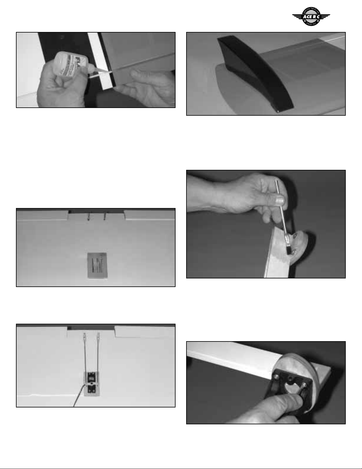
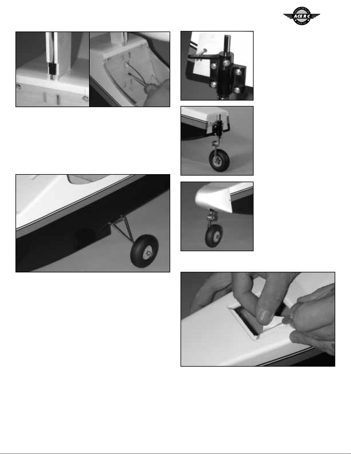
Cut a groove in the top of the leading edge of the stab to accom-
modate the nyrod. Glue the nyrod triangular spacer onto the top of
the stab (cut away a strip of covering material first).
The outer nyrod is secured to the spacer with the nylon clamp
and wood screw furnished. It should also be glued along the leading
edge of the fin. We prefer "Zap-a-dap-a-goo", Shoe-goo", or equivalent
for this operation. CA will not stick well to the nyrod. Use masking
tape to hold while the glue dries. Also glue the outer nyrod where it
exits the fuselage and where it passes through the bulkheads.
When the glue is dry, a white covering material is furnished to
cover the exposed nyrod, if desired.
Hookup on both ends of
the inner nyrod is done via a
threaded stud and nylon clevis.
Thread a clevis onto one of the
studs so some of the threads are
exposed on the inside of the cle-
vis. Then thread this assembly
into one end of the long inner
nyrod. Insert the other end into
the outer nyrod starting at the
stabilizer end. Determine the
proper position for the elevator
control horn and mount it using
the bolts and backplate fur-
nished. Repeat for the rudder.
Locate the plastic water
rudder. Place it on the rudder so
it is in the "kicked-up" mode;
i.e., flush with the bottom and
rear of the rudder. Drill a 1/8"
hole through both the water
rudder and the rudder, using the
location that is marked on the
water rudder as a guide. Secure
with the furnished 4mm screw
and locking nut. Tighten until
the water rudder is held firmly
in the down position, yet can be
kicked-up when it hits some-
thing harder than water.
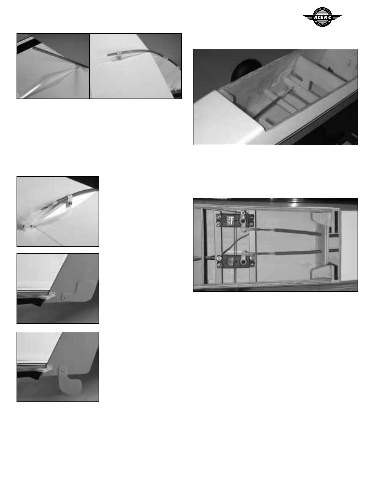
Radio Installation
Installation of the rudder and elevator servos are next.
The servo rails are laminated from two pieces of 1/8" ply to form
a part that is 1/4" x 3/8". They rest on top of the doubler that is sup-
porting the landing gear tubes. One rail fits all the way to the rear of
the doubler, and the other is spaced forward to fit the servos being
used. Plywood "U" shaped mounts further secure the rail in place. Go
ahead and install the servo rails at this time.
Install the servos next. The nosegear is linked via an EZ connect
and the inner nyrods are hooked to the servo arms with a threaded
stud and nylon clevis. Trim the nyrods to length as needed.
The receiver and battery pack should be foam mounted in the
compartment ahead of the servos. It is suggested that the receiver be
protected from water by putting it in a plastic bag or balloon. It is also
suggested to build a platform to rest the receiver on. That way if water
does get into the hull, the receiver will stay up out of the water. Also
note that you may need a servo extension cable for the throttle servo
as well as the aileron servo.
You may find it necessary to move the battery pack into the for-
ward compartment of the fuselage to achieve proper balance. If so, an
access hatch is furnished plus there is already a hole in the bulkhead
for the cable to pass through.
A good way to mount the switch is with a Dubro Kwik Switch
Mount. It is easy to install and relatively water tight. Mount it up high
in the fuselage, right under the wing saddle doubler.
Photo 30
Photo 31
Photo 32
Photo 33
Photo 34
Photo 28 Photo 29

11
FINAL ASSEMBLY
The wing is secured to the
fuselage with 4X40mm socket
head bolts and blind nuts. If the
hardwood wing hold down
blocks are not already glued in,
epoxy them in dropping the top
surface 1/8" below the top edge
of the fuselage side; this will
allow for the dihedral angle.
Put the wing into position on the fuselage with the dowels insert-
ed in the front bulkhead. Mark for the bolt holes as shown. Drill a
3/16" hole through the wing and the block, keeping the drill perpen-
dicular to the top surface of the wing.
Remove the wing and drill the holes in the mounting blocks out
to 7/32". Install the blind nuts furnished on the bottom side of the
blocks and use bolts to draw the prongs of the blind nut firmly into the
block. Bolt the wing on and check that it sits down on the wing sad-
dle properly. Fit as needed.
Turn the
fuselage over and
use "Zap-a-dap-a-
goo" to fasten the
formed plastic
keel to the mid-
dle of the bottom
of the fuselage,
lining the rear
edge up with the
rear edge of the
"step".
Your Seamaster is ready for final assembly. Reinstall the engine
pylon assembly and put everything back together. It is time for the CG
check.
Center of Gravity
Your Seamaster should balance 3 to 3-1/2" back from the leading
edge of the wing. We advise you use an indelible marker to indicate
this area on the bottom side of the wing, close to the fuselage; or, you
can make a mark on both sides of the fuselage right below the wing.
With the airplane suspended at this point with your fingertips,the
plane should balance level.
If nose weight is needed, move your battery into the forward
compartment using the access hatch provided. Move it as far forward
as needed for proper balance. Only use additional weight if absolute-
ly necessary.
Control Throws
Make sure all your control surfaces are going in the proper direc-
tion relative to the transmitter commands. Set the control surface
throws as follows for the initial flights. These may be adjusted later for
personal preference.
Elevator: 1/2”up, 1/2”down
Ailerons: 3/8”up, 3/8”down
Rudder: 1”left, 1”right
(measured at rear edge of control surface)
Since you will be flying off of water, some precautions should be
exercised to prevent water going into unwanted places. It is suggest-
ed to seal the wing-to-fuselage joint. The easiest and quickest way to
do this is to use silicone sealant. Begin by covering the center bottom
of the wing with plastic wrap; bring it around the leading and trailing
edges and hold it in place with some tape,keeping it as wrinkle-free as
possible. Now run a bead of silicone sealant all around the fuselage
wing saddle area where the wing contacts it. Install the wing in place
immediately, using the bolts and washers. Let dry overnight. Remove
the wing and use a sharp razor blade to trim off the excess silicone.
You should now have a virtually watertight seal for the wing. If your
hatch is not a good tight fit, you may want to do the same for it.
Your receiver and battery pack should be encased in a plastic bag
with a rubber band to hold the bag around the wire leads. Then wrap
them in foam rubber as usual.
Now go over all your covering material seams and inspect them
for integrity.
Flying off water
Unlike most airplanes on floats, when flying the Seamaster off of
water there is very little you have to worry about different from flying
off of land. One, Murphy’s Law will apply. Even though you have your
most dependable engine on the Seamaster, it will quit on you in the
middle of the pond! Have some way of retrieving your plane.
You will find that with the water rudder deployed, taxiing with
the Seamaster is easy even in a moderate wind. As you accelerate for
takeoff,just keep neutral elevator until the plane is“on step”and flying
speed is attained. A touch of up will break the plane from the water
and you are in the air.
Landings, too, are much like on land, except you don’t want to
land at a full flare stall. Keep a bit of throttle in it and land with the
airplane level and with some speed. After touchdown, pull the throt-
tle back to idle and let the plane slow up on its own.
If you are like us, you will find yourself shooting touch-and-go’s
continuously and enjoying the thrill of flying with the tranquil beauty
of the water. We hope the Seamaster provides you many hours of
pleasure flying this unique airplane. Your comments are welcome.
Photo 38
Photo 35
Photo 36
Photo 37
3/8”
3-1/4”
Holes are 3/8”from
the trailing edge,
3-1/4”apart centered
(each 1-5/8”from ctr).

12
FLIGHT
PRE-FLIGHT CHECK LIST
❐1. Check all control surfaces for possible looseness or deterioration.
❐2. Check all screws, clevises, nuts and all other connectors to
make sure they are securely fastened.
❐3. Check which radio frequencies are being used. Do not turn
on your radio until absolutely sure you are the only one oper-
ating on that frequency.
❐4. Check for proper operation of all control surfaces.
❐5. Check the level of charge in both the transmitter and receiver
batteries before flying.
❐6. Range check the radio both with and without the engine running!
Follow the radio manufacturers instructions for this.
POST-FLIGHT CHECK LIST
❐1. Be sure that both the transmitter and receiver switches are
turned off.
❐2. Drain all excess fuel from the tank. Fuel left in the tank for
extended periods can“gunk up”the tank,fittings and carburetor.
❐3. Clean the plane with paper towels and a light-duty spray
cleanser. Keeping your plane clean will make it last longer
and keep it looking nice.
❐4. Put a few drops of after-run or light oil in the carburetor and
turn the prop over a few times (without the glow plug ignited)
to distribute the oil throughout the engine.
❐5. Inspect the prop and replace it if any chips or cracks are found.
❐6. Inspect the entire plane for covering tears, new dings and
dents, loose screws and connectors and any other wear and
tear.
SAFETY PRECAUTIONS
1. Wear safety glasses when starting and running all model engines.
2. Model engine fuel is very flammable and the flame is very
dangerous because it is almost invisible! Do not smoke or allow
sparks, high heat or other flames near the fuel.
3. Do not run model engines inside a garage or other closed room as
they give off large amounts of deadly carbon monoxide gas.
4. Do not run model engines around gravel, sand or other loose
debris. These materials will be ingested through the carburetor
and can also be kicked up by the prop.
5. Always stay behind the propeller when the engine is running.
Make all engine adjustments from behind the engine.
6. Do not allow loose clothing or other loose objects close to the prop.
7. To stop an engine, cut off the fuel or air supply to the engine.
Do not throw rags or other objects into the prop to stop the
engine.
8. Do not touch the engine or muffler during or right after it has
been running–it gets very hot!
Table of contents
Other ACE RC Toy manuals