Ace RELIANCE User manual

V2.3 2 | P a g e
ACE RELIANCE SENSOR OPERATIONS MANUAL
Table of Contents
Contents
1. Product Description .................................................................................................................................... 3
2. Product Specifications................................................................................................................................. 5
3 Installation tools and materials................................................................................................................... 6
4. TEC cable preparation................................................................................................................................. 9
5. Downhole Instrument Installation: 10 kPSI Sensor Model.......................................................................14
6. Sensor and cable Integrity testing..............................................................................................................23
7. 1kPSI Sensor Model Installation................................................................................................................24
1. Surface Read-Out Unit Set-up...................................................................................................................24
9. Sensor and Cable Integrity Monitoring During Run in Hole....................................................................33

V2.3 3 | P a g e
ACE RELIANCE SENSOR OPERATIONS MANUAL
1. Product Description
ACE Reliance is a downhole sensor designed to be deployed in non-ESP wells (GasLift, PCP, Rod Lift, Hydraulic
Lift, …).
ACE Reliance sensor consists of two main components - a downhole instrument and a surface read-out unit. The
downhole instrument is a completely sealed, welded device. The instrument electronics are not exposed to
damaging well fluid caused by leaking threads, seals, O-rings or drain/fill valves. Power to downhole sensor and
communication is provided by a TEC cable.
Figure 1
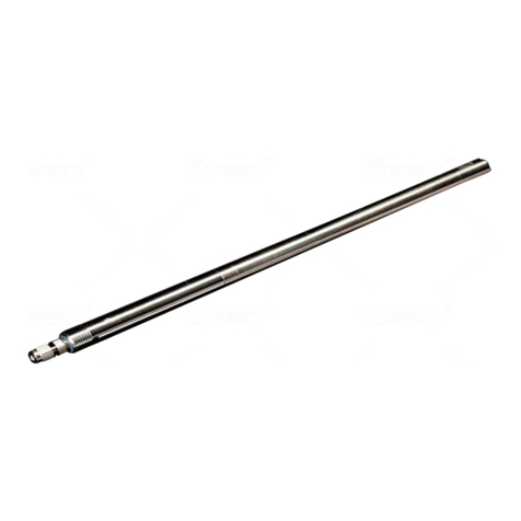
Downhole instrument (10 K PSI model)
Figure 2.1
Downhole instrument (1K PSI model)

V2.3 4 | P a g e
ACE RELIANCE SENSOR OPERATIONS MANUAL
The surface readout (SRU) provides optically isolated RS-485 and RS-232 Modbus ports for remote
connections to virtually all wired SCADA control systems. The premium SRU2i readout includes all the features
of the SRU then adds a higher resolution display, Ethernet, USB, analog outputs and relays plus built in data-
logging that will record unlimited readings from the downhole device to removable SD memory cards. The SRU2i
also includes insulation monitoring. The SRU3i adds direct Wi-Fi local connection plus direct connection to Baker
Hughes VSD’s. The SRU's operates from nominal 120 VAC50/60Hzline voltage. ACE Optix is a battery
powered, solar power capable version.

V2.3 5 | P a g e
ACE RELIANCE SENSOR OPERATIONS MANUAL
Figure 3
Surface read-out unit (SRU)
2. Product Specifications
Table 1
Downhole tool specifications
Pressure Range
0-1,000 psi
0-10,000 psi
Pressure Accuracy
0.2%
0.2%
Pressure Resolution (0.01 to 1 PSI
depending on readout)
0.0305 psi
0.305 psi
Transducer Type
Silicon Strain Gauge
Temperature Range
32 - 257 deg °F (0–125 deg °C)
32-257 °F (0–125 °C)
32-302 °F (0–150 °C)
Diameter
0.75”
0.82”
Length
17”
17”
Weight
1.34 lbs ( 610 g)
1.5 lbs ( 680g)
Material
SS316L
SS Duplex 2205
Thread at the pressure port at the bottom
of the sensor
1/8"-27 NPT
1/8"-27 NPT
TEC cable recommended
1/8" TEC 316
1/4" TEC 2205 Duplex
AWG 16
Table 2
Surface Read-out Unit (SRU) specifications
SRU
SRU2i
SRU3i
ACE Optix
Power Required
115 VAC +/- 15%
50/60HZ
115VAC +/-15% 50/60Hz
115 VAC +/-15% 50/60Hz
10-32 VDC 0.25A
(solar capable)
Display Type
6 digit Alpha Numeric
LED
8 digit Alpha Numeric LED
Status LED
Status LED
Modbus RS-485 (
isolated)
3 wire standard
3 wire standard
3 wire standard
3 wire standard
Modbus RS-232
3 wire, no handshaking
required
3 wire, no handshaking
required
3 wire standard
3 wire standard
USB Modbus (
isolated)
Standard USB “B”
Standard USB-A
Standard USB-A
Ethernet Modbus (
Isolated)
Standard CAT5E 8 Pin
connector

V2.3 6 | P a g e
ACE RELIANCE SENSOR OPERATIONS MANUAL
WiFi Interface
Standard worldwide, license
fee 802.11 b/g/n
Standard worldwide,
license fee 802.11 b/g/n
Analog Outputs (
isolated)
4x 0-20 Ma User
configurable ( SRU2
sources power)
Relay Outputs (
Isolated)
2x Form C User
configurable 240VAC / 8
Amps
SD data logger
Up to 32 GByte ( SDHC
mode supported)
Internal
Internal memory
32 GByte (X version)
32GB
GPS
Internal + External port
Operating
Temperature
0 deg F –158 deg F ( -
18 deg C –50 deg C)
0 deg F –158 deg F ( -18
deg C –50 deg C)
0 deg F –158 deg F ( -18
deg C to 50 deg C)
0 deg F –158 deg F ( -18
deg C –50 deg C)
Dimensions
6.00” x 5.25” x 2.25”
9.50” x 5.75” x 1.75”
7.38 x 5.75” x 1.75”
5.25”x1”x3.3”
Weight
1.5 lbs
2 lbs
2 lbs
2lbs
UL Certification
Conforms to UL Std.
610-10-1
Conforms to UL Std. 610-
10-1
Conforms to UL Std. 610-
10-1
N/A
CSA Certification
Certified to CAN/CSA
Std. C22.2 # 61010-1
Certified to CAN/CSA Std.
C22.2 # 61010-1
Certified to CAN/CSA Std.
C22.2 # 61010-1
N/A
3 Installation tools and materials
Wrench 9/16” (slim version; Proto J3430)
Wrench 5/8”
Wrench 1/2”
Wrench 3/4”
Petroleum jelly (lip balm)
Pins (included with the instrument)
ACE Downhole strip gauge
Crimp tool
Vise grips
Tube cutter
Figure 3.1 ACE Downhole strip gauge

V2.3 11 | P a g e
ACE RELIANCE SENSOR OPERATIONS MANUAL
4.3 Hold the TEC cable with wise grips on both ends of the groove and wiggle until the end section of the tube
breaks loose. Then remove the tube (fig 12 and fig 13).
Figure 12
Figure 13
4.4 Use the cable cutter to remove a length of the Teflon insulation as per dimensions of the ACE cable strip gauge
(fig 14)

V2.3 12 | P a g e
ACE RELIANCE SENSOR OPERATIONS MANUAL
Figure 14. TEC cable stripping dimensions as per the ACE Downhole strip gauge
4.5 Insert the end of the TEC cable wire into the pin (fig 15).
Figure 15
4.6 Terminate with a pin using the crimp tool (fig 16). If it is assembled but does not match the gauge then cut off

V2.3 14 | P a g e
ACE RELIANCE SENSOR OPERATIONS MANUAL
5.Downhole Instrument Installation: 10 kPSI Sensor Model
5.1 Unscrew the stop block cover from the instrument housing (fig 17)
Figure 17
5.2 Slide TEC cable through the stop block cover (fig 18)
Figure 18
5.3 Retrieve the stop block assembly from the stop block cover and dismantle the stop block. Check the orientation
of the cone and the ferrule (fig 19 and fig 20)
Stop block cover
Stop block
assembly
Sensor housing

V2.3 16 | P a g e
ACE RELIANCE SENSOR OPERATIONS MANUAL
Figure 22
5.6 Hold the TEC cable in place, unscrew the short nut from the instrument base and slide it further right along
the TEC cable. Hold the TEC cable near the pin with your left hand and use your right hand to shake off the
cone and the ferrule from the instrument head nut. Ensure that the orientation of the cone and the ferrule is
correct (fig 23).
Figure 23
5.7 Push the cone into the instrument head. Either by manually holding the cable and cone, or by using tape hold the
cone against the tubing (fig 24).
The correct orientation of the cone (left)
and the ferrule (right)

V2.3 17 | P a g e
ACE RELIANCE SENSOR OPERATIONS MANUAL
Figure 24 Ferrule pressed into the head and a masking tape applied
5.8 Withdraw the tubing from the gauge and verify that the cone is at least 3/16” over the tubing (fig 25)
Figure 25
5.8 Apply petroleum jelly (lip balm) on the threat at the at the instrument head connection thread (fig 26)
The cone is pushed into the
head of the instrument
The tape applied next to the cone
to hold it in this location
The cone sits about 3/16”
from the edge of the tune

V2.3 18 | P a g e
ACE RELIANCE SENSOR OPERATIONS MANUAL
Figure 26
5.9.1 Screw the short nut back on the instrument head and tighten it up with your fingers (fig 27).
Figure 27
5.9.2 Insert the 9/16” wrench onto the short nut (right hand side) and the 5/8” wrench into the grove below the
thread (left hand side). Apply 1 ¼ turns until it feels tight enough (fig 28 and fig 29)
WARNING: DO NOT OVERTIGHTEN AS IT CAN DEFORM THE CONE.
Figure 28
Step 2. Apply petroleum jelly on the
circumference of the thread
Step 1. Verify the connection between the
TEC cable and the instrument head is tight.
Push it in more if needed.
Table of contents
Other Ace Accessories manuals

Ace
Ace 3035748 (AC-6195) User manual

Ace
Ace LED Lighted Pushbutton with Courtesy Light... User manual

Ace
Ace 3196425 Installation guide

Ace
Ace Weatherproof Long Range Wireless Chime with Chime Extender... User manual

Ace
Ace ac-29 User manual

Ace
Ace Reliance 1K User manual

Ace
Ace 3035466 (AC-6180) User manual

Ace
Ace Hardwired Mechanical Chime 598-1223-01 User manual

Ace
Ace 3003530 User manual
Ace
Ace Lighted Wireless Push Button Accessory... User manual