4Q Half-Wave SCR Chassis
Adjustable Speed Drive
for PMDC or Field Wound Brushed Motors
RGH100-5-FLD 14300 De La Tour Drive
South Beloit, IL 61080
Phone: (815) 624-6915
Fax: (815) 624-6965
www.americancontrolelectronics.com
REGENERATIVE
BRAKE SWITCH
(OPTIONAL)
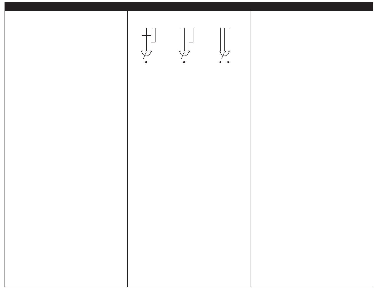
Line Input Speed Potenometer
Connect the AC line power leads to terminals L1 and L2. ACE recommends the use of a double-pole, Use a 50K ohm, 1/4 W potenometer for speed control. Connect the counter-clockwise end of the
single throw master power switch. The switch should be rated at a minimum of 125 VAC and 200% of potenometer to S0, wiper to S2, and the clockwise end to S1. If the potenometer works
motor current. inversely of desired funconality, (i.e. to increase motor speed, you must turn the potenometer
counterclockwire), power off the drive and swap the S0 and S1 connecons. See the Operaon secon
Motor for alternave wiring setups.
Connect the DC armature leads to terminals A1 and A2. If the motor does not spin in the desired
direcon, power down the drive and reverse these connecons. Regenerave Brake
Short terminals S0 and T0 to regeneravely brake the motor to zero speed. The me it takes the motor
Field to come a stop is dependent on load inera, fricon, and the FWD TQ and REV TQ trim pot sengs.
Connect the field leads to terminals F1 and F2 for a 100 VDC field. Open terminals S0 and T0 to accelerate the motor to set speed.
Do not make any connecons to F1 and F2 if using a permanent magnet motor. Do not use the regenerave braking for emergency stopping.
LOGIC (TOP BOARD) POWER (BOTTOM BOARD)
Connections
FUSE
STOP
SWITCH
AC LINE
VOLTAGE
115 VAC
50K OHM
SPEED ADJUST
POTENTIOMETER
CW
NOTE: DO NOT make
any connections to
F1 and F2 if using a
permanent magnet motor.
Installation
Mounng
• Drive components are sensive to electrostac discharge. Avoid direct contact with the circuit
• board. Hold the drive by the chassis only.
• Protect the drive from dirt, moisture, and accidental contact.
• Provide sufficient room for access to the terminal block and calibraon trim pots.
• Mount the drive away from heat sources. Operate the drive within the specified ambient operang
• temperature range.
• Prevent loose connecons by avoiding excessive vibraon of the drive.
• Mount the drive with its board in either a horizontal or vercal plane. Six 0.19” (5 mm) wide slots
• in the chassis accept #8 pan head screws. Fasten either the large base or the narrow flange of the
• chassis to the subplate.
Wiring
Use 18 - 24 AWG wire for logic wiring.
Use 14 - 16 AWG wire for AC line (L1, L2) and motor (A1, A2) wiring.
Shielding Guidelines
As a general rule, ACE recommends shielding of all conductors. If it is not praccal to shield power
conductors, ACE recommends shielding all logic-level leads. If shielding of logic-level leads is not
praccal, the user should twist all logic leads with themselves to minimize induced noise. Refer to
the user’s manual for details on earth grounding shielded wires and filtering.
Fusing
ACE drives require an external line fuse for protecon. Use fast acng fuses rated for 125 VAC or
higher and 150% of the maximum armature current. Fuse the HOT leg of the AC line.
ALL DIMENSIONS IN INCHES [MILLIMETERS]
Dimensions
Safety Warnings
• DO NOT INSTALL, REMOVE, OR REWIRE THIS EQUIPMENT WITH POWER APPLIED. Have a
• qualified electrical technician install, adjust and service this equipment. Follow the Naonal
•Electrical Code and all other applicable electrical and safety codes, including the provisions of the
• Occupaonal Safety and Health Act (OSHA), when installing equipment.
• Circuit potenals are at 115 above earth ground. Avoid direct contact with the printed circuit board
• or with circuit elements to prevent the risk of serious injury or fatality. Use a non-metallic
• screwdriver for adjusng the calibraon trim pots. Use approved personal protecon equipment
• and insulated tools if working on this drive with power applied.
• Reduce the chance of an electrical fire, shock, or explosion by using proper grounding, over-current
• protecon, thermal protecon, and enclosure. Follow sound maintenance procedures.
• ACE strongly recommends the installaon of a master power switch in the line voltage input. The
•switch contacts should be rated for 125 VAC and 200% of motor nameplate current.
• Removing AC line power is the only acceptable method for emergency stopping. Do not use
• regenerave braking, decelerang to minimum speed, or coasng to a stop for emergency stopping.
• They may not stop a drive that is malfunconing. Removing AC line power is the only acceptable
•method for emergency stopping.
• Line starng and stopping (applying and removing AC line voltage) is recommended for infrequent
• starng and stopping of a drive only. Regenerave braking, decelerang to minimum speed, or
• coasng to a stop is recommended for frequent starts and stops. Frequent starng and stopping can
•produce high torque. This may cause damage to motors.
• Do not disconnect any of the motor leads from the drive unless power is removed or the drive is
• disabled. Opening any one lead while the drive is running may destroy the drive.
• The field output is for shunt wound motors only. Do not make any connecons to F1 and F2 when
•using a permanent magnet motor.
• Under no circumstances should power and logic level wires be bundled together.
• Be sure potenometer tabs do no make contact with the potenometer’s body. Grounding the
•input will cause damage to the drive.
READ ALL SAFETY WARNINGS BEFORE INSTALLING THIS EQUIPMENT
.............................................................115 VAC ± 10%, 50/60 Hz, single phase
...................................................................................................1.77 at base speed
.................................................................................................................100 VDC
...................................................................................................1 Amp
.............................................................................................1 second
.............................................................................................1 second
.........................................0 to ± 10 VDC
......................................................................................200K ohms
..................................................................................................3% base speed
........................................................................................................................50:1
...........................................................................................0.5G maximum
...............................................................................................0.1G maximum
...................................................................................10°C - 55°C
..............................................................................................................................0.6 lbs
AC Line Voltage
Form Factor
Field Voltage
Maximum Field Current
Acceleraon Time Range
Deceleraon Time Range
Analog Input Voltage Range (Signal must be isolated)
Input Impedance (S0 to S2)
Load Regulaon
Speed Range
Vibraon (0 - 50 Hz)
(>50 Hz)
Ambient Temperature Range
Weight
1/8 - 1/2
Armature
Horsepower
Range
5.0
Connuous
Armature
Current (Amps)
0 - 75
Armature
Voltage Range
(VDC)
115
Line
Voltage
(VAC)
RGH100-5
Model
Specifications