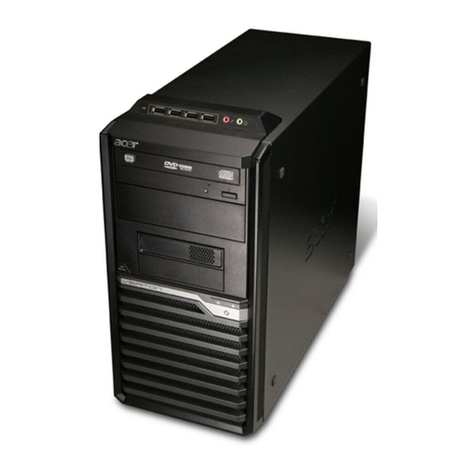
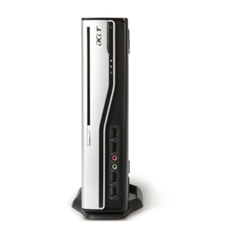
Acer AcerPower F2 User manual

AcerPower F2
Service Guide
PRINTED IN TAIWAN
Service guide files and updates are available
on the AIPG/CSD web; for more information,
please refer to http://csd.acer.com.tw

II
Revision History
Please refer to the table below for the updates made on AcerPower F2service guide.
Date Chapter Updates

III
Copyright
Copyright © 2004 by Acer Incorporated. All rights reserved. No part of this publication may be reproduced,
transmitted, transcribed, stored in a retrieval system, or translated into any language or computer language, in
any form or by any means, electronic, mechanical, magnetic, optical, chemical, manual or otherwise, without
the prior written permission of Acer Incorporated.
Disclaimer
The information in this guide is subject to change without notice.
Acer Incorporated makes no representations or warranties, either expressed or implied, with respect to the
contents hereof and specifically disclaims any warranties of merchantability or fitness for any particular
purpose. Any Acer Incorporated software described in this manual is sold or licensed "as is". Should the
programs prove defective following their purchase, the buyer (and not Acer Incorporated, its distributor, or its
dealer) assumes the entire cost of all necessary servicing, repair, and any incidental or consequential
damages resulting from any defect in the software.
Acer is a registered trademark of Acer Corporation.
Intel is a registered trademark of Intel Corporation.
Pentium 4 and Celeron are trademarks of Intel Corporation.
Other brand and product names are trademarks and/or registered trademarks of their respective holders.

IV
Conventions
The following conventions are used in this manual:
Screen messages Denotes actual messages thatappear
on screen.
NOTE Gives bitsand piecesof additional
information related to the current
topic.
WARNING Alertsyou to anydamage that might
result from doing or not doing specific
actions.
CAUTION Gives precautionary measures to
avoid possible hardware or software
problems.
IMPORTANT Reminds you to do specific actions
relevant to the accomplishment of
procedures.

V
Preface
Before using this information and the product it supports, please read the following general information.
1. This Service Guide provides you with all technical information relating to the BASIC CONFIGURATION
decided for Acer's "global" product offering. To better fit local market requirements and enhance product
competitiveness, your regional office MAY have decided to extend the functionality of a machine (e.g.
add-on card, modem, or extra memory capability). These LOCALIZED FEATURES will NOT be covered
in this generic service guide. In such cases, please contact your regional offices or the responsible
personnel/channel to provide you with further technical details.
2. Please note WHEN ORDERING FRU PARTS, that you should check the most up-to-date information
available on your regional web or channel. If, for whatever reason, a part number change is made, it will
not be noted in the printed Service Guide. For ACER-AUTHORIZED SERVICE PROVIDERS, your Acer
office may have a DIFFERENT part number code to those given in the FRU list of this printed Service
Guide. You MUST use the list provided by your regional Acer office to order FRU parts for repair and
service of customer machines.

VI

VII
Table of Contents
Chapter 1 System Specifications 1
Overview . . . . . . . . . . . . . . . . . . . . . . . . . . . . . . . . . . . . . . . . . . . . . . . . . . . .1
Features & Specification . . . . . . . . . . . . . . . . . . . . . . . . . . . . . . . . . . . . . . . .2
AcerPower F2 Front Panel . . . . . . . . . . . . . . . . . . . . . . . . . . . . . . . . . . . . . . 4
AcerPower F2 Rear Panel . . . . . . . . . . . . . . . . . . . . . . . . . . . . . . . . . . . . . . 5
Hardware Specifications and Configurations . . . . . . . . . . . . . . . . . . . . . . . . 8
Power Management Function (ACPI support function) . . . . . . . . . . . . . . . 16
Chapter 2 System Utilities 17
Entering Setup . . . . . . . . . . . . . . . . . . . . . . . . . . . . . . . . . . . . . . . . . . . . . . 18
Product Information . . . . . . . . . . . . . . . . . . . . . . . . . . . . . . . . . . . . . . . . . . 19
Standard CMOS Features . . . . . . . . . . . . . . . . . . . . . . . . . . . . . . . . . . . . . 20
Advanced BIOS Features . . . . . . . . . . . . . . . . . . . . . . . . . . . . . . . . . . . . . . 23
Advanced Chipset Features . . . . . . . . . . . . . . . . . . . . . . . . . . . . . . . . . . . . 25
Integrated Peripherals . . . . . . . . . . . . . . . . . . . . . . . . . . . . . . . . . . . . . . . . 28
Power Mangement Setup . . . . . . . . . . . . . . . . . . . . . . . . . . . . . . . . . . . . . . 31
PnP/PCI Configuration . . . . . . . . . . . . . . . . . . . . . . . . . . . . . . . . . . . . . . . . 35
PC Health Status . . . . . . . . . . . . . . . . . . . . . . . . . . . . . . . . . . . . . . . . . . . . 36
Frequency/Voltage Control . . . . . . . . . . . . . . . . . . . . . . . . . . . . . . . . . . . . . 37
Load Fail-Safe Defaults . . . . . . . . . . . . . . . . . . . . . . . . . . . . . . . . . . . . . . . 38
Load Default Settings . . . . . . . . . . . . . . . . . . . . . . . . . . . . . . . . . . . . . . . . . 39
Set Supervisor/User Password . . . . . . . . . . . . . . . . . . . . . . . . . . . . . . . . . . 40
Save and Exit Setup . . . . . . . . . . . . . . . . . . . . . . . . . . . . . . . . . . . . . . . . . . 41
Exit Without Saving . . . . . . . . . . . . . . . . . . . . . . . . . . . . . . . . . . . . . . . . . . . 42
Chapter 3 Machine Disassembly and Replacement 43
General Information . . . . . . . . . . . . . . . . . . . . . . . . . . . . . . . . . . . . . . . . . .44
Before You Begin . . . . . . . . . . . . . . . . . . . . . . . . . . . . . . . . . . . . . . . . . . . .44
Standard Disassembly Procedure . . . . . . . . . . . . . . . . . . . . . . . . . . . . . . .45
Opening the System . . . . . . . . . . . . . . . . . . . . . . . . . . . . . . . . . . . . . . . . . .45
Removing the Front Panel . . . . . . . . . . . . . . . . . . . . . . . . . . . . . . . . . . . . .45
Removing the Cables . . . . . . . . . . . . . . . . . . . . . . . . . . . . . . . . . . . . . . . . .45
Removing the Modem card,CD-ROM,Floppy and HDD . . . . . . . . . . . . . . .46
Removing the Power Supply . . . . . . . . . . . . . . . . . . . . . . . . . . . . . . . . . . .47
Removing the Heatsink and the CPU . . . . . . . . . . . . . . . . . . . . . . . . . . . . .48
Removing the Memory . . . . . . . . . . . . . . . . . . . . . . . . . . . . . . . . . . . . . . . .48
Removing the Mainboard . . . . . . . . . . . . . . . . . . . . . . . . . . . . . . . . . . . . . .49
Removing the Power Button . . . . . . . . . . . . . . . . . . . . . . . . . . . . . . . . . . . .49
Removing the LED Module . . . . . . . . . . . . . . . . . . . . . . . . . . . . . . . . . . . . .49
Removing the Daughter Board . . . . . . . . . . . . . . . . . . . . . . . . . . . . . . . . . .49
Standard Reassembly Procedure . . . . . . . . . . . . . . . . . . . . . . . . . . . . . . . .50
Installing the Daughter Board . . . . . . . . . . . . . . . . . . . . . . . . . . . . . . . . . . .50
Installing the LED Module . . . . . . . . . . . . . . . . . . . . . . . . . . . . . . . . . . . . . .50
Installing the Power Button . . . . . . . . . . . . . . . . . . . . . . . . . . . . . . . . . . . . .50
Installing the Mainboard . . . . . . . . . . . . . . . . . . . . . . . . . . . . . . . . . . . . . . .50
Installing the Heatsink and the CPU . . . . . . . . . . . . . . . . . . . . . . . . . . . . . .51
Installing the Memory . . . . . . . . . . . . . . . . . . . . . . . . . . . . . . . . . . . . . . . . .51
Installing the Power Supply . . . . . . . . . . . . . . . . . . . . . . . . . . . . . . . . . . . .52
Installing the Modem card,CD-ROM, Floppy and HDD . . . . . . . . . . . . . . .52
Installing the Cables . . . . . . . . . . . . . . . . . . . . . . . . . . . . . . . . . . . . . . . . . .53
Installing the Front Panel . . . . . . . . . . . . . . . . . . . . . . . . . . . . . . . . . . . . . .54
Closing System . . . . . . . . . . . . . . . . . . . . . . . . . . . . . . . . . . . . . . . . . . . . . .54

VIII
Table of Contents
Chapter 4 Troubleshooting 55
Power-On Self-Test (POST) . . . . . . . . . . . . . . . . . . . . . . . . . . . . . . . . . . . . 56
Post Check Points . . . . . . . . . . . . . . . . . . . . . . . . . . . . . . . . . . . . . . . . . . . 57
POST Error Messages List . . . . . . . . . . . . . . . . . . . . . . . . . . . . . . . . . . . . . 63
Error Symptoms List . . . . . . . . . . . . . . . . . . . . . . . . . . . . . . . . . . . . . . . . . . 65
Chapter 5 Jumper and Connector Information 71
Checking Jumper Settings . . . . . . . . . . . . . . . . . . . . . . . . . . . . . . . . . . . . . . 71
Setting Jumpers . . . . . . . . . . . . . . . . . . . . . . . . . . . . . . . . . . . . . . . . . . . . . . 71
Connectors and Jumpers . . . . . . . . . . . . . . . . . . . . . . . . . . . . . . . . . . . . . . 72
Pin Definition . . . . . . . . . . . . . . . . . . . . . . . . . . . . . . . . . . . . . . . . . . . . . . . . 74
Connectors and Headers Definition . . . . . . . . . . . . . . . . . . . . . . . . . . . . . . . 74
Expansion I/O . . . . . . . . . . . . . . . . . . . . . . . . . . . . . . . . . . . . . . . . . . . . . . . 77
Chapter 6 FRU (Field Replaceable Unit) List 81
Appendix A Model Definition and Configuration 89
Appendix B Test Compatible Components 91
Microsoft WinXP Home Environment Test . . . . . . . . . . . . . . . . . . . . . . . . . 92
Appendix C Online Support Information 95

Chapter 1 1
Overview
AcerPower F2 is a versatile, high-power system, supporting Intel Socket478 CPUs. The computer uses
Peripheral Component Interface (PCI) and Accelerated Graphics Port (AGP) design. This improves system
efficiency and helps the system support varied multimedia and software applications.
TIntel Pentium 4/Celeron CPU
TSystem Memory DDR 266/33/400, 2 DIMM Slots, expendable to 2GB
TPower Management function
T3.5 inch floppy drive
TCD-ROM, DVD-ROM, CD-RW (52x/24x), DVD/CD-RW combo or DVD writer
THigh-capacity, Enhanced-IDE drive
TSupport USB 2.0 high performance peripherals
T3D quality audio system via onboard audio controller
TAudio-in/Line-in, Audio-out/Line-out, Headphone out and external Microphone in Jacks
System Specifications
Chapter 1

2Chapter 1
Features & Specifications
CPU
TSupport Intel Pentium 4 / Celeron (Socket 478) processor
TSupport Intel Hyper Threading Technology
Chipset
TIntel 865GV + ICH5
Memory
TDDR SDRAM PC2100(DDR266)/PC2700(DDR333)/PC3200(DDR400) 184-pin, 2 DIMM Slots,
expandable to 2GB
Graphics
TOn-die VGA
T1 VGA port
AGP/PCI
TThree PCI 2.2 5V slots
FDD
TOne FDD slot supports 1.44MB/3 mode 3.5” devices
IDE
TSlot Type: 40 pin IDE slot
TSlot Quantity: 2
TTransfer rate support:
TPIO Mode: 0/1/2/3/4
TUltra DMA 66/100/133
TStorage Type support:
THDD/CD-ROM/CD-RW/DVD
TZip 250
TATA-100 transfer rate
Audio
T3D quality audio system via onboard audio controller
TConnectors support:
TLine-in/Line-out (rear)
TMicrophone-in (rear)/Microphone-in (front) (Default)
THeadphone Out (front) (Default)
LAN
TSupports 10/100MB ethernet environment
USB
TConnectors Quantity:
TOn-board: 4 (rear)/2(Front)

Chapter 1 3
TConnector Pin: 4
TTransfer Rate:
TUSB 2.0/1.1
BIOS
TAward BIOS with Plug andPlay BIOS
TACPI, SMBIOS 2.3, Green and Boot Block
TProvides DMI 2.0, WFM 2.0, WOL, WOR, chassis intrusion and SM Bus for system management
Others
TSuspend to RAM/Disk
TPC2001 Compliant
TSupport PS2 Keyboard/Mouse and USB Keyboard/Mouse wake up function

4Chapter 1
AcerPower F2 Front Panel
The computer’s front panel consists of the following:
Label Description
1 Optical Drive
2 FDD Drive
3 Power Button
4 Universal Serial Bus (USB) Ports
5 Microphone Jack
6 Speaker/Headphone jack

Chapter 1 5
AcerPower F2 Rear Panel
Label Description
1 Power Code Socket
2 Voltage Selector Switch
3 Fan Aperture
4 PS/2 Keyboard Port
5 PS/2 Mouse Connector
6 Serial Connector
7 Printer Connector
8 Monitor Connector
9 USB Connector
10 RJ-45 Ethernet Connector
11 Microphone Jack
12 Line-Out Jack
13 Line-In Jack
14 Extension Card Slots

6Chapter 1
MainBoard Layout
Lable Component
1394_HDER2 1394 Connector
BAT1 Battery
CN11 12V Connector
CN15 CPU Fan Connector
CN18,20 DIMM Port
CN2 COM1
CN21,22 S-ATA Port
CN24,26 Primary IDE Connector, Secondary IDE Connector
CN25 Main Power Connector
CN27 Floppy Connector
CN3 PS2-KBMS
CN30 Dual USB & RJ45
CN35 Front Panel Header
CN4 Parallel Print Port
ˣ˖˜ˆ
˨˅ˌ
˖ˡ˅ˉ
ˣ˖˜˅
ˣ˖˜˄
˄ˆˌˇ˲˛˗˘˥˅
˙˲˨˦˕˄
˙˲˨˦˕˅
˝ˆ
˖ˡˌ
˝ˣ˄
˖ˡˆˈ
˨˅ˊ
˖ˡ˅˄
˖ˡ˅˅
˖ˡ˅ˇ
˖ˡ˅ˊ
˖ˡ˅ˈ
˨˅ˋ
˖ˡ˄ˋ
˦ˣ˗˜˙
˨ˇˋ
˖ˡˈ
˖ˡˆ˃
˖ˢˡˡ˄
˖ˡ˄
˖ˡˇ
˖ˡ˅
˖ˡˆ
˖ˡ˄˄
˕˔˧˄
˖ˢˡ˄
˨˄ˊ
˨˄ˉ
˖ˡ˅˃
˖ˡ˄ˈ

Chapter 1 7
CN5 Audio Port
CN9 SYS FAN Connector
CON1 COM2 Header
CI\ONN1 USB Port
F_USB1,2 Front USB Connector
JP1 Clear CMOS
PCI1,2,3 PCI Slot
U16 478-pin CPU Slot
U17 865GV Chipset
U27 BIOS
U28 I/O Connector
U2 Audio Controller, Nearby U29
U29 1394 Controller
U48 LAN Controller
Lable Component

8Chapter 1
Block Diagram
USB2.0 Port 5
Front Panel
USB2.0 Port 6
IDE CONN 1
IDE CONN 2
ALC 655
AC 97 Code 2.3
4MB
Firmware HUB
W83627HF
Super I/O
Drive Connector
Floppy
Serial
ParallelPS2
Keyboard / Mouse
USB2.0 Port 8
USB2.0 Port 7
USB2.0 Port 4
USB2.0 Port 1
USB2.0 Port 3
Back Panel
USB2.0 Port 2
S-ATA0
S-ATA1
Intel Pentium 4 Willamette/
Serial port
uATX Form Factor
PCI Slot 1
PCI Slot 2
PCI Slot 3
PCI Interface
VT 6307(Optional)
1394 PORT
RTL8100C
10/100 BT LAN
Northwood/Prescott processor
GMCH
932 Pin FC-BGA
uPGA 478 ZIP Socket
DIMM1
DIMM1
Channel A DDR
Channel B DDR
DDR 400/333/266
DDR 400/333/266
400/533/800 FSB
VGA Connector
3 Phase PWM
VRD 9/10
CK-409 Clock
Morgan Hill
460 Pin mBGA
ICH5

Chapter 1 9
Hardware Specifications and Configurations
NOTE: The BIOS can be overwritten/upgraded by using “AFLASH” utility (AFLASH.EXE).
System Board Major Chip
Item Specification
System Core Logic Intel 865GV
W83627HF (Champion I/O Bridge)
ICH5 (Champion South Bridge)
Super I/O Controller W83627HF
LAN Controller RTL8100C
Memory Controller Build in Intel 865GV (Champ North Bridge)
E-IDE Controller Build in ICH5 (champion South Bridge)
Keyboard Controller Build in W83627HF
RTC Build in ICH5
Processor
Item Specification
Type Intel Pentium 4 Northwood processor in Flip Chip Pin Grid
Array (FC-PGA) package
Slot Socket 478
Speed Depends on CPU, which is local configured
Bus Frequency 400/533/800 MHz
Voltage Processor voltage can be detected by any system without
setting any jumper
BIOS
Item Specification
BIOS code programmer Award
BIOS version v6.0
BIOS ROM type LPC Flash ROM
BIOS ROM size 4MB
BIOS ROM package 32-pin PLCC package
Support protocol PCIX 1.0,PCI 2.2,APM 1.2,VESA/DPMS (VBE/PM V1.1),
SMBIOS 2.3, E-IDE 1.1, ACPI 1.0b,ESCD1.03, PnP 1.0a,
Bootable CD-ROM 1.0, USB 1.1, UHCI 1.0, ANSI ATA 3.0
ATAPI
Boot from CD-ROM feature Yes
Support to LS-120 drive Yes
Support to BIOS boot block feature Yes
BIOS Password Control Yes

10 Chapter 1
BIOS Hotkey List
Hotkey Function Description
cEnter BIOS Setup Utility Press while the system is booting to
enter BIOS Setup Utility.
System Memory
Item Specification
Onboard Embedded Memory Size 0
Memory Socket Number 2 Sockets
Supported Memory Size per Socket 128 MB/ 256 MB/ 512 MB/ 1024 MB
Supported Maximum Memory Size 2GB (1024MB x2 )
Supported Memory Speed 266/333/400 MHz
Supported memory voltage 2.5V
Support memory module package 184-pin DIMM
Support to parity check feature Yes
Support to Error Correction Code (ECC)
feature
Yes
Memory module combinations You can install memory modules in any combination as
long as they match the above specifications.
VRM
Function VRM Specification Typical Voltage Power Source Maximum Output
CPU VRM VRM10 0.8375~1.6v 12 Voltage 91A
CPU VRM VRM 9.0 1.1-1.85 Voltage 12 Voltage 70A
Cache Memory
Item Specification
First-Level Cache Configurations
Cache function control Enable/Disable by BIOS Setup
Second-Level Cache Configurations
The information below is only applicable to system installed with a Pentium 4 processor
Tag RAM Location On Processor
L2 Cache RAM Location On Processor
L2 Cache RAM type PBSRAM (Pipelined-burst Synchronous RAM)
L2 Cache RAM size Depends on CPU, which is local configured
L2 Cache RAM speed Full of the processor core clock frequency (Advanced Transfer Cache)
L2 Cache function control Enable/Disable by BIOS Setup
L2 Cache scheme Fixed in write-back
LAN Interface
Item Specification
LAN Controller RTL8100C LAN Controllers

Chapter 1 11
LAN Controller Resident Bus PCIX Bus
LAN Port ONE RJ-45 on board
Function Control Enable/Disable by BIOS Setup
IDE Interface
Item Specification
IDE Controller Built-in ServerWorks CSB5 (Champion South Bridge)
IDE Controller Resident Bus PCI bus
Number IDE Channel 2
Supported IDE Interface E-IDE (up to PIO mode-4, DMA mode 2 and Ultra DMA-33), ANSIS
ATA rev. 3.0, ATAPI
Supports LS-120 Yes
Supports bootable CD-ROM Yes
Function Control Enable/Disable by BIOS setup
Diskette Drive Interface
Item Specification
Diskette Drive Controller Build-in NS W83627HF super I/O controller
Diskette Drive Controller Resident Bus LPC Bus
Supported Diskette Drive Formats 1.44MB, 2.88MB format and slim type diskette drive
Function Control Enable/Disable by BIOS Setup
Serial Port
Item Specification
Serial port controller Build-in W83627HF Super I/O Controller
Serial port controller resident bus LPC Bus
Number of serial port 2
Serial port location CON1,CN2
16550 UART support Yes
Connector type 9-pin D-type female connector
Optional serial port I/O address
(via BIOS Setup)
3F8h
2F8h
3E8h
2E8h
Optional serial port IRQ
(via BIOS Setup)
IRQ4
IRQ11
LAN Interface
Item Specification

12 Chapter 1
USB Port
Item Specification
Universal HCI USB 2.0
USB Class Support legacy keyboard for legacy mode
Memory Address Map
Address Size Function
0000000 - 009FFFF 640 KB System Memory Onboard DRAM
00A0000-00BFFFF 128 KB Video RAM Reserved for Graphics Display
Buffer
Non-Cacheable
00C0000-00CFFFF 32 KB I/O Expansion ROM Reserved for ROM on I/O
Adapters
00D0000-00D3FFF 16 KB I/O Expansion ROM Reserved for ROM on I/O
Adapters
00D4000-00D7FFF 16 KB I/O Expansion ROM Reserved for ROM on I/O
Adapters
00D8000-00DBFFF 16 KB I/O Expansion ROM Reserved for ROM on I/O
Adapters
00DC000-00DFFFF 16 KB I/O Expansion ROM Reserved for ROM on I/O
Adapters
00E0000-00E7FFF 32 KB for SCSI BIOS Reserved for SCSI BIOS
00E8000-00EFFFF 32 KB Reserved Onboard
00F0000-00FFFFF 64 KB BIOS System ROM BIOS (ROM)
System RAM BIOS (DRAM)
0100000-0F9FFFF System Memory Onboard DRAM
0FA0000-0FFFFFF 384 KB I/O Card Memory Reserved for Memory Map
I/O Card
Non-Cacheable
1000000-FFFFFFF System Memory Onboard DRAM
PCI INTx# and IDSEL Assignment Map
PCI INTx # PCI Devices Device IDSEL: ADxx
INTA# ADIMM-slot N
INTB# PCI-Slot1 AD16
INTC# PCI-Slot2 AD17
INTD# PCI-Slot3 AD18
PCI Slot IRQ Routing Map
PCI INTX# INTA INTB INTC INTD Bus Mastering
PCI slot 1 INTBJ INTCJ INTDJ INTAJ Enabled
PCI slot 2 INTGJ INTFJ INTEJ INTHJ Enabled
Other manuals for AcerPower F2
2
Table of contents
Other Acer Desktop manuals

Acer
Acer AcerPower 4100 User manual

Acer
Acer Ferrari 3400 User manual

Acer
Acer Veriton N2010G Thin Client User manual

Acer
Acer Veriton 3500 User manual

Acer
Acer Aspire X1920 User manual

Acer
Acer Aspire T100 User manual

Acer
Acer Veriton 7100 User manual

Acer
Acer Aspire X1600 User manual

Acer
Acer Aspire 6100 User manual

Acer
Acer Aspire Z5600 Series User manual

Acer
Acer Veriton M480G User manual

Acer
Acer Aspire C22-820 User manual

Acer
Acer 2010 User manual

Acer
Acer Aspire E500 User manual

Acer
Acer ASPIRE X5400 User manual

Acer
Acer Veriton 5200 User manual

Acer
Acer AcerPower F6 User manual

Acer
Acer AcerPower 4100 Manual

Acer
Acer Aspire E571 User manual

Acer
Acer Veriton D461 User manual