Acer Veriton 3200 User manual

Veriton 3200
Service Guide
PART NO.: 49.38H02.031
DOC. NO.: SG359-0103A PRINTED IN TAIWAN
Service guide files and updates are available
on the AIPG/CSD web; for more information,
please refer to http://csd.acer.com.tw

II
Copyright
Copyright © 1999 by Acer Incorporated. All rights reserved. No part of this publication may be reproduced,
transmitted, transcribed, stored in a retrieval system, or translated into any language or computer language, in
any form or by any means, electronic, mechanical, magnetic, optical, chemical, manual or otherwise, without
the prior written permission of Acer Incorporated.
Disclaimer
The information in this guide is subject to change without notice.
Acer Incorporated makes no representations or warranties, either expressed or implied, with respect to the
contents hereof and specifically disclaims any warranties of merchantability or fitness for any particular
purpose. Any Acer Incorporated software described in this manual is sold or licensed "as is". Should the
programs prove defective following their purchase, the buyer (and not Acer Incorporated, its distributor, or its
dealer) assumes the entire cost of all necessary servicing, repair, and any incidental or consequential
damages resulting from any defect in the software.
Acer is a registered trademark of Acer Corporation.
Intel is a registered trademark of Intel Corporation.
Pentium and Pentium II/III are trademarks of Intel Corporation.
Other brand and product names are trademarks and/or registered trademarks of their respective holders.

III
Conventions
The following conventions are used in this manual:
Screen messages Denotes actual messages thatappear
on screen.
NOTE Gives bits and pieces of additional
information related to the current
topic.
WARNING Alerts you to any damage that might
result from doing or not doing specific
actions.
CAUTION Gives precautionary measures to
avoid possible hardware or software
problems.
IMPORTANT Reminds you to do specific actions
relevant to the accomplishment of
procedures.

IV
Preface
Before using this information and the product it supports, please read the following general information.
1. This Service Guide provides you with all technical information relating to the BASIC CONFIGURATION
decided for Acer's "global" product offering. To better fit local market requirements and enhance product
competitiveness, your regional office MAY have decided to extend the functionality of a machine (e.g.
add-on card, modem, or extra memory capability). These LOCALIZED FEATURES will NOT be covered
in this generic service guide. In such cases, please contact your regional offices or the responsible
personnel/channel to provide you with further technical details.
2. Please note WHEN ORDERING FRU PARTS, that you should check the most up-to-date information
available on your regional web or channel. If, for whatever reason, a part number change is made, it will
not be noted in the printed Service Guide. For ACER-AUTHORIZED SERVICE PROVIDERS, your Acer
office may have a DIFFERENT part number code to those given in the FRU list of this printed Service
Guide. You MUST use the list provided by your regional Acer office to order FRU parts for repair and
service of customer machines.

V
Table of Contents
Chapter 1 System Specifications 1
Overview . . . . . . . . . . . . . . . . . . . . . . . . . . . . . . . . . . . . . . . . . . . . . . . . . . . . . . . 1
Features . . . . . . . . . . . . . . . . . . . . . . . . . . . . . . . . . . . . . . . . . . . . . . . . . . . . . . .2
Performance . . . . . . . . . . . . . . . . . . . . . . . . . . . . . . . . . . . . . . . . . . . . . . . . .2
Multimedia . . . . . . . . . . . . . . . . . . . . . . . . . . . . . . . . . . . . . . . . . . . . . . . . . . .2
Connectivity . . . . . . . . . . . . . . . . . . . . . . . . . . . . . . . . . . . . . . . . . . . . . . . . .2
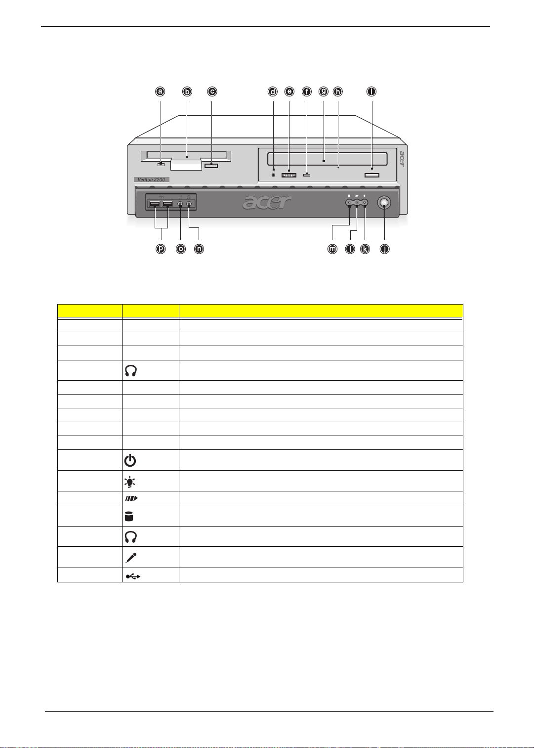
Front Panel . . . . . . . . . . . . . . . . . . . . . . . . . . . . . . . . . . . . . . . . . . . . . . . . . . . . . .3
Rear panel . . . . . . . . . . . . . . . . . . . . . . . . . . . . . . . . . . . . . . . . . . . . . . . . . . . . . .4
Main Board Layout . . . . . . . . . . . . . . . . . . . . . . . . . . . . . . . . . . . . . . . . . . . . . . . .5
Keyboard . . . . . . . . . . . . . . . . . . . . . . . . . . . . . . . . . . . . . . . . . . . . . . . . . . . . . . .6
Programmable keys . . . . . . . . . . . . . . . . . . . . . . . . . . . . . . . . . . . . . . . . . . .6
Internet/Suspend keys . . . . . . . . . . . . . . . . . . . . . . . . . . . . . . . . . . . . . . . . .6
Multimedia keys . . . . . . . . . . . . . . . . . . . . . . . . . . . . . . . . . . . . . . . . . . . . . .7
Volume control/Mute . . . . . . . . . . . . . . . . . . . . . . . . . . . . . . . . . . . . . . . . . . .7
Cursor keys . . . . . . . . . . . . . . . . . . . . . . . . . . . . . . . . . . . . . . . . . . . . . . . . . .7
Lock keys . . . . . . . . . . . . . . . . . . . . . . . . . . . . . . . . . . . . . . . . . . . . . . . . . . .7
Windows keys . . . . . . . . . . . . . . . . . . . . . . . . . . . . . . . . . . . . . . . . . . . . . . . .8
Hardware Specifications and Configurations . . . . . . . . . . . . . . . . . . . . . . . . . . . .9
Power Management Functions . . . . . . . . . . . . . . . . . . . . . . . . . . . . . . . . . . . . . .18
Chapter 2 System Utilities 20
Entering Setup . . . . . . . . . . . . . . . . . . . . . . . . . . . . . . . . . . . . . . . . . . . . . . . . . .21
System Information . . . . . . . . . . . . . . . . . . . . . . . . . . . . . . . . . . . . . . . . . . . . . . .23
Product Information . . . . . . . . . . . . . . . . . . . . . . . . . . . . . . . . . . . . . . . . . . . . . .25
Disk Drives . . . . . . . . . . . . . . . . . . . . . . . . . . . . . . . . . . . . . . . . . . . . . . . . . . . . .26
Onboard Peripherals . . . . . . . . . . . . . . . . . . . . . . . . . . . . . . . . . . . . . . . . . . . . . .30
Power Management . . . . . . . . . . . . . . . . . . . . . . . . . . . . . . . . . . . . . . . . . . . . . .32
Boot Options . . . . . . . . . . . . . . . . . . . . . . . . . . . . . . . . . . . . . . . . . . . . . . . . . . . .34
Date and Time . . . . . . . . . . . . . . . . . . . . . . . . . . . . . . . . . . . . . . . . . . . . . . . . . .36
System Security . . . . . . . . . . . . . . . . . . . . . . . . . . . . . . . . . . . . . . . . . . . . . . . . .37
Setting a Password . . . . . . . . . . . . . . . . . . . . . . . . . . . . . . . . . . . . . . . . . . .38
Changing or Removing the Password . . . . . . . . . . . . . . . . . . . . . . . . . . . .39
Bypassing the Password . . . . . . . . . . . . . . . . . . . . . . . . . . . . . . . . . . . . . . .39
Advanced Options . . . . . . . . . . . . . . . . . . . . . . . . . . . . . . . . . . . . . . . . . . . . . . .40
Memory/Cache Options . . . . . . . . . . . . . . . . . . . . . . . . . . . . . . . . . . . . . . .40
PnP/PCI Options . . . . . . . . . . . . . . . . . . . . . . . . . . . . . . . . . . . . . . . . . . . . .42
Chipset Settings . . . . . . . . . . . . . . . . . . . . . . . . . . . . . . . . . . . . . . . . . . . . .43
Load Default Settings . . . . . . . . . . . . . . . . . . . . . . . . . . . . . . . . . . . . . . . . . . . . .45
Abort Settings Change . . . . . . . . . . . . . . . . . . . . . . . . . . . . . . . . . . . . . . . . . . . .46
Exiting Setup . . . . . . . . . . . . . . . . . . . . . . . . . . . . . . . . . . . . . . . . . . . . . . . . . . . .47
Chapter 3 Machine Disassembly and Replacement 48
General Information . . . . . . . . . . . . . . . . . . . . . . . . . . . . . . . . . . . . . . . . . . . . . .49
Before You Begin . . . . . . . . . . . . . . . . . . . . . . . . . . . . . . . . . . . . . . . . . . . .49
Disassembly Procedure Flowchart . . . . . . . . . . . . . . . . . . . . . . . . . . . . . . . . . . .50
Opening the Housing . . . . . . . . . . . . . . . . . . . . . . . . . . . . . . . . . . . . . . . . . . . . .51
Removing the Housing Cover . . . . . . . . . . . . . . . . . . . . . . . . . . . . . . . . . . .51
Removing the Front Panel . . . . . . . . . . . . . . . . . . . . . . . . . . . . . . . . . . . . . . . . .52
Removing the EMI Audio Cover . . . . . . . . . . . . . . . . . . . . . . . . . . . . . . . . . . . . .52
Removing the Modem Card . . . . . . . . . . . . . . . . . . . . . . . . . . . . . . . . . . . . . . . .53
Removing the AGP VGA Card . . . . . . . . . . . . . . . . . . . . . . . . . . . . . . . . . . . . . .53
Removing the FDD and DVD Frame . . . . . . . . . . . . . . . . . . . . . . . . . . . . . . . . .53
Removing the USB and Audio Board . . . . . . . . . . . . . . . . . . . . . . . . . . . . . . . . .55
Removing the Hard Disk Drive . . . . . . . . . . . . . . . . . . . . . . . . . . . . . . . . . . . . . .56

VI
Table of Contents
Removing the DIMM . . . . . . . . . . . . . . . . . . . . . . . . . . . . . . . . . . . . . . . . . . . . . .57
Removing the Power Supply . . . . . . . . . . . . . . . . . . . . . . . . . . . . . . . . . . . . . . .57
Removing the RTC Battery . . . . . . . . . . . . . . . . . . . . . . . . . . . . . . . . . . . . . . . . .58
Removing the Processor . . . . . . . . . . . . . . . . . . . . . . . . . . . . . . . . . . . . . . . . . .58
Removing the Main board . . . . . . . . . . . . . . . . . . . . . . . . . . . . . . . . . . . . . . . . . .59
Chapter 4 Troubleshooting 60
Power-On Self-Test (POST) . . . . . . . . . . . . . . . . . . . . . . . . . . . . . . . . . . . . . . . .61
POST Error Messages List . . . . . . . . . . . . . . . . . . . . . . . . . . . . . . . . . . . . . . . . .62
Error Symptoms List . . . . . . . . . . . . . . . . . . . . . . . . . . . . . . . . . . . . . . . . . . . . . .64
Undetermined Problems . . . . . . . . . . . . . . . . . . . . . . . . . . . . . . . . . . . . . . . . . . .68
Chapter 5 Jumper and Connector Information 70
Jumpers and Connectors . . . . . . . . . . . . . . . . . . . . . . . . . . . . . . . . . . . . . . . . . .70
Connector Description . . . . . . . . . . . . . . . . . . . . . . . . . . . . . . . . . . . . . . . .71
Jumper Setting . . . . . . . . . . . . . . . . . . . . . . . . . . . . . . . . . . . . . . . . . . . . . .72
Chapter 6 FRU (Field Replaceable Unit) List 74
Veriton 3200 Exploded Diagram . . . . . . . . . . . . . . . . . . . . . . . . . . . . . . . . . . . .75
Appendix A Model Definition and Configuration 84
Veriton 3200 . . . . . . . . . . . . . . . . . . . . . . . . . . . . . . . . . . . . . . . . . . . . . . . . . . . .84
Appendix B Test Compatible Components 86
MS DOS V6.22 Environment Test . . . . . . . . . . . . . . . . . . . . . . . . . . . . . . . . . . .87
Microsoft Windows ME Environment Test . . . . . . . . . . . . . . . . . . . . . . . . . . . . .88
Microsoft Windows 2000 Professional Environment Test . . . . . . . . . . . . . . . . . .89
Microsoft NT 4.0 Workstation Environment Test . . . . . . . . . . . . . . . . . . . . . . . .90
IBM OS/2 Warp 4.0 Environment Test . . . . . . . . . . . . . . . . . . . . . . . . . . . . . . . .91
Novell Netware 4.12 & 5.1 Environment Test . . . . . . . . . . . . . . . . . . . . . . . . . . .92
SCO UNIX/Red Hat Linux Environment Test . . . . . . . . . . . . . . . . . . . . . . . . . . .93
Appendix C Online Support Information 94
Index 96

VII
Table of Contents

Chapter 1 1
Overview
The Veriton 3200 supports Intel® Pentium III Flip Chip-Pin Grid Array (FC-PGA) processor based Micro ATX,
IBM PC/AT compatible system with PCI/AGP bus.
System Specifications
Chapter 1

2Chapter 1
Features
Performance
!Intel Pentium® III and Celeron processor with integrated L2 cache memory in Flip Chip (FC)-PGA
370 socket form factor
!Expandable system memory to a maximum of 512 MB
NOTE: Due to a chipset limitation you can only use two DIMM sockets (DIMM1 and DIMM2) when you install
a 133 MHZ front side bus CPU. If you install a 100 MHz front side bus CPU then you can use all of the
DIMM sockets.
!Power management function
!Reserved keylock and intrusion alarm function
!3.5-inch floppy disk drive
!CD-ROM/DVD-ROM/CD-RW drive
!High-capacity, Enhanced-IDE hard disk
Multimedia
!128-bit graphics accelerator onboard with an additional AGP card slot
NOTE: The onboard VGA function will automatically be disabled when you install an AGP VGA card in the
AGP slot.
!3-D quality audio system via onboard audio controller
!Supports CRT (cathode-ray tube) monitors
!Audio-in/Line-in, Audio-out/Line-out, Headphone-out, Mic-in, and Game/MIDI interfaces
NOTE: The system has two microphone-in ports (front and rear). However, you can not use both of them at
the same time. The default setting for your system enables the microphone-in port in front and disables
the one at the back. You must first enable the front microphone-in port before you can use it.
Connectivity
!PS/2 mouse and keyboard interface
!One parallel interface and two serial interfaces (internal and external)
!Universal Serial Bus (USB) ports (available on front and rear panels)
!High-speed fax/data PCI modem (optional)
!10Base-T/100Base-TX network support with remote wake-up function

Chapter 1 3
Front Panel
Label Icon Component
a Floppy disk drive light-emitting diode (LED)
b 3.5-inch floppy disk drive
c Floppy disk drive eject button
d CD-ROM/DVD-ROM/CD-RW Headphone/Earphone port
e Volume tuner
f CD-ROM/DVD-ROM/CD-RW LED
g CD-ROM/DVD-ROM/CD-RW tray
h CD-ROM/DVD-ROM/CD-RW emergency eject slot
i Stop/Eject button
jPowerswitch
k Power LED
l System activity LED
m Hard disk drive activity LED
n Headphone-out port
oMicrophone-in port*
* The system has two microphone-in ports (front and rear). However, you can not use both of them at the
same time. The default setting for your system enables the microphone-in port in front and disables the
one at the back. You must first enable the front microphone-in port before you can use it.
p USB ports

4Chapter 1
Rear panel
Label Icon Color Component
a Power supply
b Voltage Selector switch
cKeyhole
d Green PS/2 mouse port
e White Network port
f Burgundy Parallel/Printer port
g Gold Game/MIDI port
hBlue
VGA port*
* The CRT monitor port is automatically disabled when an add-on VGA card is installed into the system.
Connect the monitor to the VGA port instead.
i Blue Handset/telephone line ports
j Expansion slots
kMicrophone-in port†
† The system has two microphone-in ports (front and rear). However, you can not use both of them at the
same time. The default setting for your system enables the microphone-in port in front and disables the
one at the back. You must first enable the front microphone-in port before you can use it.
l Light blue Audio-in/Line-in jack
m Lime Audio-out/Line-out jack
n Blue CRT monitor port
o Teal or Turquoise Serial port
pBlackUSBports
q Purple PS/2 keyboard port
r Power cord socket

Chapter 1 5
Main Board Layout
1 Floppy disk drive connector 18 DIMM sockets 1
2 IDE 1 HDD connector 19 ATX power connector
3 IDE 2 HDD connector 20 FC-PGA CPU socket
4 Battery 21 Intel 82815 chipset
5 Firmware HUB (BIOS) 22 3-pin CPU fan connector
6 IDE LED connector 23 CD-ROM audio connector
7 Power LED connector 24 Audio connector for USB-audio board
8 Wake on LAN connector 25 AGP slot
9 Turbo/LAN active LED connector 26 PCI slots 1
10 ATX power switch 27 PCI slots 2
11 Buzzer 28 Audio chipset
12 USB connector for USB-audio board 29 FAX-VOICE
13 Intrusion alarm connector 30 Serial port 2 (COM2) connector (optional)
14 Intel 82801BA chipset 31 PS/2 mouse (upper) and keyboard (lower) ports
15 PCI slots 3 32 Network (upper) and USB (lower) ports
16 DIMM sockets 3 33 Parallel (upper), VGA (lower right) and serial
port 1 (lower left) ports
17 DIMM sockets 2 34 MIDI/Game (Upper), Line-Out (Left), Line-In
(Middle), and Mic-In Ports (Right)
U13
123456
7
8
9
10
11
12
13
14
15
16
17
18
19
20
21
22
23 24 2526
27
28 29 30
31
32
33
34

6Chapter 1
Keyboard
The keyboard that came with your computer has full-sized keys that include separate cursor keys, two
Windows keys, and twelve function keys.
Programmable keys
The programmable keys help you directly access a URL (Web site) or launch any program, file, or application
in yoursystem. The fifth key is set to launch the media player.If you want to configure the settings of each key,
right-click on the Magic Keyboard icon located on your Windows desktop.
Internet/Suspend keys
The Internet/Suspend keys consist of three buttons:
Icon Key Description
Email Launches your email application.
Web browser Launches your current default browser.
Suspend/Resume Press this button to put the system to sleep. Press again to
wake the system up.

Chapter 1 7
Multimedia keys
The multimedia keys allow you to play, pause, stop, step forward, or step back a song or movie conveniently
using your keyboard.
Volume control/Mute
The volume control/mute knob controls the speaker volume. Turn it clockwise or counterclockwise to
adjust the volume. Press it to toggle between mute and sound.
Cursor keys
The cursor keys, also called the arrow keys, let you move the cursor around the screen. They serve the same
function as the arrow keys on the numeric keypad when the Num Lock is toggled off.
Lock keys
The keyboard has three lock keys which you can toggle on and off to switch between two functions
Icon Key Description
Play/Pause Press to start playing an audio or video file. Press again to
pause.
Stop Press to stop playing the audio or video file.
Forward Press to skip forward to the next file and start playing.
Backward Press to skip backward to the previous file and start playing.
Lock Key Description
Caps Lock When activated, all alphabetic characters typed appear in uppercase
(same function as pressing Shift + <letter>).
Num Lock When activated, the keypad is set to numeric mode; i.e., the keys
function as a calculator (complete with arithmetic operators such as +, -,
*, and /).
Scroll Lock When activated, the screen moves one line up or down when you press
the up arrow or down arrow respectively. Take note that Scroll Lock
may not work with some applications.

8Chapter 1
Windows keys
The keyboard has two keys that perform Windows-specific functions
.
Key Description
Windows logo key Start button. Combinations with this key perform special functions, such
as:
Windows +Tab: Activate the next Taskbar button
Windows +E: Explore My Computer
Windows +F: Find Document
Windows +M: Minimize All
Shift +Windows +M: Undo Minimize All
Windows +R: Display Run dialog box
Application key Opens the applications context menu (same function as clicking the
right button of the mouse).

Chapter 1 9
Hardware Specifications and Configurations
NOTE: The BIOS can be overwritten/upgraded using the AFLASH utility (AFLASH.EXE).
Processor
Item Specification
Type Intel® Celeron and Intel® Pentium III processors with Flip Chip-PGA package
Slot Socket 370
Speed Celeron processor upto 766 MHz and Pentium III processor upto 1 GHz
Minimum operating speed 0 MHz (If Stop CPU Clock in Sleep State the BIOS Setup is set to Enabled.)
Voltage Processor voltage can be detected by the system without setting any jumper.
BIOS
Item Specification
BIOS code programmer Acer
BIOS version V4.0
BIOS ROM type Flash ROM
BIOS ROM size 4Mbits
BIOS ROM package 32-pin DIP package
Support protocol PCI 2.1, APM1.2, DMI 2.00.1, E-IDE, ACPI 1.0, ESCD 1.03, ANSI ATA 3.0, PnP
1a, Bootable CD-ROM 1.0, ATAPI
Boot from CD-ROM feature Yes
Support to LS-120 drive Yes
Support to BIOS boot block feature No
BIOS Hotkey List
Hotkey Function Description
++ Enter BIOS Setup Utility Press while the system is booting to enter BIOS
Setup Utility.
F8 Enable hidden page of BIOS Setup Utility Press in BIOS Setup Utility main menu screen,
the Advanced Options menu then appears.
The items on the Advanced Options menu are:
Memory/Cache Options
PnP/PCI Options
Alt + F4 Enable hidden page of BIOS Setup Utility Press in BIOS Setup Utility main menu screen,
the Advanced Options menu then appears.
The items on the Advanced Options menu are:
Memory/Cache Options
PnP/PCI Options
Chips Options
System Memory
Item Specification
Memory socket number 3 sockets (3 banks)
Support memory size per socket 64/128/256MB
Support maximum memory size 512MB
Support memory type SDRAM
Support memory speed 100/133MHz (PC100/ PC133)

10 Chapter 1
NOTE: For Memory Combinations-133 MHz, if memory is double-sided, only slot 1 and slot 2 will work. The
maximum memory size of S58M is 512M. Users can make different combinations of double-sided
memory in slot 1 and slot 2; single-sided memory in slot 1, 2, and 3, but, the total memory should not go
beyond 512M
.
Support memory voltage 3.3 V
Support memory module package 168-pin DIMM
Support to parity check feature Yes
Support to Error Correction Code (ECC)
feature. Yes
Memory module combinations You can install memory modules in any combination as long as they match
the Memory Combination specifications.
Memory Combinations-100 MHz
DIMM 1 DIMM 2 DIMM 3 TOTAL
128M 128M 128M 384M
256M 256M 0M 512M
64M 64M 64M 192M
32M 32M 32M 96M
16M 16M 16M 48M
Memory Combinations-133 MHz
DIMM 1 DIMM 2 DIMM 3 TOTAL
256/DS M 256/DS M 0M 512M
64/SS M 64/SS M 64/SS M 192M
128/SS M 128/SS M 128/SS M 384M
Cache Memory
Item Specification
First-Level Cache Configurations
Cache function control Enable/Disable by BIOS Setup (Advanced options)
Second-Level Cache Configurations
Below information is only applicable to system with installed Intel® Celeron and Pentium III processors.
L2 Cache RAM type PBSRAM
L2 Cache RAM size Pentium III processor: 256 KB
Celeron processor: 128 KB
L2 Cache RAM speed One-half the processor core clock frequency ?????
L2 Cache RAM voltage Pentium III processor: 1.65V
Celeron processor: ????/
L2 Cache function control Enable/Disable by BIOS Setup
L2 Cache scheme Fixed in write-back
System Memory
Item Specification

Chapter 1 11
*32 - 24bpp color data is processed using a 32bpp data format
.
NOTE: You may disable the on-board video function in the BIOS Utility.
Video Interface
Item Specification
Video controller Embedded in Intel 815E
Video controller resident bus AGP bus (AGP 2X/4X for AGP slot)
Video interface support Video YUV texture in all texture formats
H/W DVD accelerator
Display Screen Resolution Bits Per Pixel
(Frequency in Hz)
8-bit Indexed
Bits Per Pixel
(Frequency in Hz)
16-bit Indexed)
Bits Per Pixel
(Frequency in Hz)
24-bit Indexed
320x240 70 70 70
320x240 70 70 70
352x480 70 70 70
352x576 70 70 70
400x300 70 70 70
512x384 70 70 70
640x400 70 70 70
640x480 60, 70, 72, 75, 85 60, 70, 72, 75, 85 60, 70, 72, 75, 85
720x480 75, 85 75, 85 75, 85
720x576 60, 75, 85 60, 75, 85 60, 75, 85
800x600 60, 70, 72, 75, 85 60, 70, 72, 75, 85 60, 70, 72, 75, 85
1024x768 60, 70, 72, 75, 85 60, 70, 72, 75, 85 60, 70, 72, 75, 85
1152x864 60, 70, 72, 75, 85 60, 70, 72, 75, 85 60, 70, 72, 75, 85
1280x720 60, 75, 85 60, 75, 85 60, 75, 85
1280x960 60, 75, 85 60, 75, 85 60, 75, 85
1280x1024 60, 70, 72, 75, 85 60, 70, 72, 75, 85 60, 70, 72, 75, 85
1600x900 60, 75, 85 60, 75, 85 60, 75, 85
1600x1200 60, 70, 72, 75, 85 Not available Not available

12 Chapter 1
Audio Interface
Item Specification
Audio controller Embedded in Intel 82801BA ICH II
Audio controller resident bus AC’97 link
Audio function control Enable/disable by BIOS Setup
Mono or stereo Stereo
Resolution 16 bits
Compatibility AC’97 2.1 compliant
Sound Blaster Pro compatible
Mixed digital and analog high performance chip
Enhanced stereo full duplex operation
High performance PCI audio accelerator
Full native DOS games compatibility
High-Quality ESFM music synthesizer
MPU-401(UART mode) interface for wavetable synthesizers and MIDI devices
Integrated dual game port
Meets PC 97/PC98 and WHQL specifications
Music synthesizer Yes
Sampling rate 44.1 KHz
MPU-401 UART support Yes
Microphone jack Supported
On audio-I/O board (connects via CN8)
Headphone jack Supported
On audio-I/O board (connects via CN8)
Package QFP64
IDE Interface
Item Specification
IDE controller Embedded in Intel 82801BA ICH II
IDE controller resident bus PCI bus
Number of IDE channel 2 on-board: 40-pin hard disk drive connector,
Support IDE interface E-IDE (up to PIO mode 4 and Ultra DMA/33, Ultra DMA/66 and Ultra DMA/100
mode 2) ANSIS ATA rev.4.0 ATAPI
Support bootable CD-ROM Yes
Floppy disk drive Interface
Item Specification
Floppy disk drive controller Embedded in LPC 47B277
Floppy disk drive controller resident bus LPC
Support FDD format 360KB, 720KB, 1.2MB, 1.44MB, 2.88MB; 3-mode

Chapter 1 13
Parallel Port
Item Specification
Parallel port controller Embedded in LPC 47B277
Parallel port controller resident bus LPC
Number of parallel ports 1
Support ECP/EPP ECP / EPP 1.7 & 1.9
Connector type 25-pin D-type female connector
Parallel port function control Enable/disable by BIOS Setup
Optional ECP DMA channel
(in BIOS Setup) DMA channel 1
DMA channel 3
Optional parallel port I/O address
(via BIOS Setup) 378h
278h
Optional parallel port IRQ
(via BIOS Setup) IRQ5
IRQ7
Serial Port
Item Specification
Serial port controller Embedded in Intel 82801BA ICH II
Serial port controller resident bus LPC
Number of serial port 2
Serial ports location CN4, COM 2
16550 UART support Yes
Connector type 10-pin connector
Optional serial port I/O address
(via BIOS Setup) 3F8h, 2F8h, 3E8h, 2E8h
Optional serial port IRQ
(via BIOS Setup) 4, 3
LAN Interface
Item Specification
LAN controller Intel 82562ET LAN controllers
LAN controller resident bus PCI bus
LAN port One RJ-45 on board (CN??)
Function control Enable/disable by BIOS Setup
Modem
Item Specification
Fax modem data baud rate (bps) 14.4K bps
Data modem data baud rate (bps) 56K bps
Voice modem Yes
Modem connector type RJ11
Full duplex Not applicable
Table of contents
Other Acer Desktop manuals

Acer
Acer VERITON 7200 User manual

Acer
Acer Altos G5450 Series User manual

Acer
Acer Aspire ZC-700G User manual

Acer
Acer ZX4830 Series User manual

Acer
Acer Aspire E650 User manual

Acer
Acer Aspire L series User manual

Acer
Acer Veriton 5200 User manual

Acer
Acer Ferrari 3400 User manual

Acer
Acer Aspire L300 User manual

Acer
Acer AcerPower F2b User manual

Acer
Acer Aspire E650 User manual

Acer
Acer Aspire E571 User manual

Acer
Acer Aspire M1640 User manual

Acer
Acer Aspire M1620 User manual

Acer
Acer Veriton 5800 Quick start guide

Acer
Acer Veriton Series User manual

Acer
Acer Veriton 3600GT Configuration guide

Acer
Acer DA241HL User manual

Acer
Acer Veriton 7600GT Quick start guide

Acer
Acer Veriton X480G User manual