Acer AT3201W User manual

System Specifications
=============================================================
Features
This LCD TV was designed with the user in mind. Here are just a few of its many features:
LCD Panel
zMax. resolution: 1366 x 768
z16 CCFTs Backlight system
zDisplay area: 31.5 inches diagonal
zDisplay color: 16.7 M colors
zInput Signal: 1-ch LVDS
zContrast ratio: 800:1 ( Typical )
zBrightness: 500 Cd/m² ( Typical )
zResponse Time: 24 ms
zViewing angle: 85° ( L ) / 85° ( R ), 85° ( U ) / 85° ( D )
I/O functions
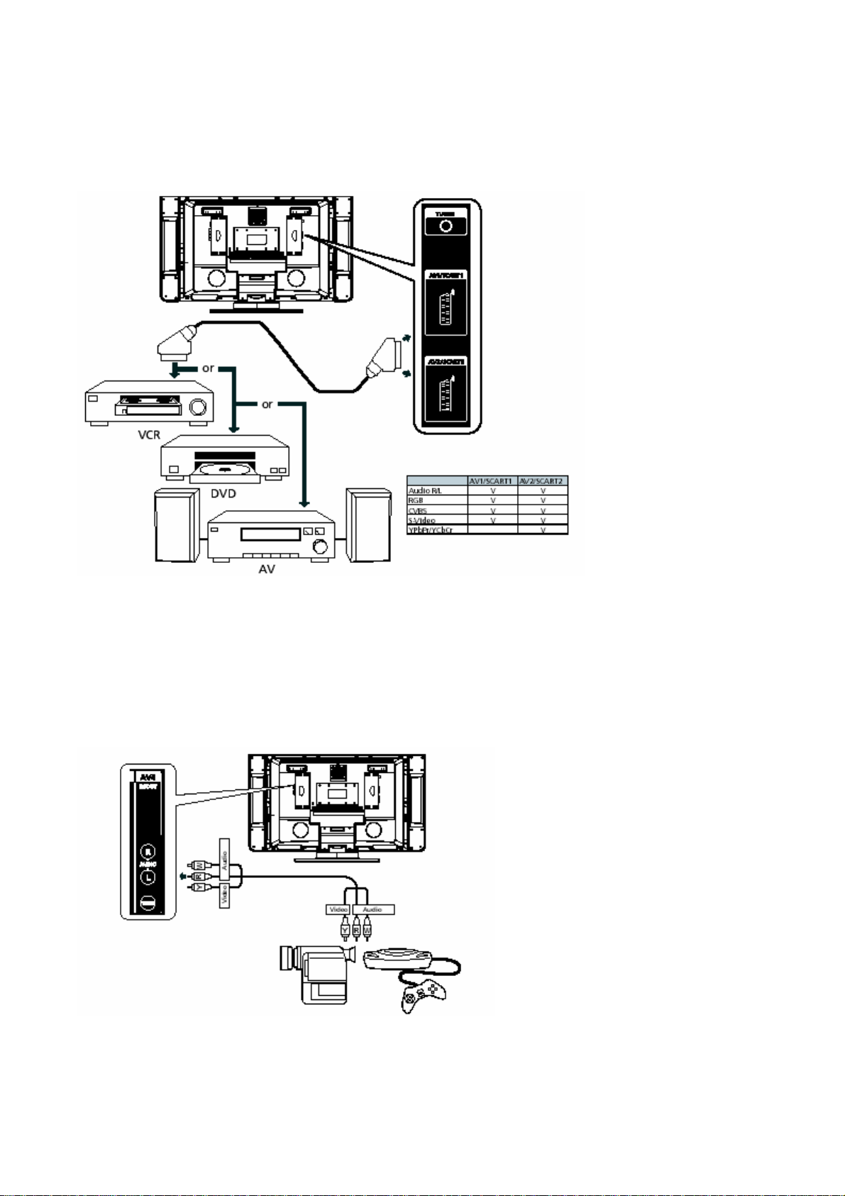
z21 pin Euro-SCART ( RGB ) for Video, S-Video, R.G.B. and Audio
z21 pin Euro-SCART ( YUV / RGB ) for Video, S-Video, YPbPr, YCbCr, RGB
and Audio
zRCA jack ( YUV and CVBS ) for YPbPr, YCbCr, Video and Audio
zS-Din for S-Video
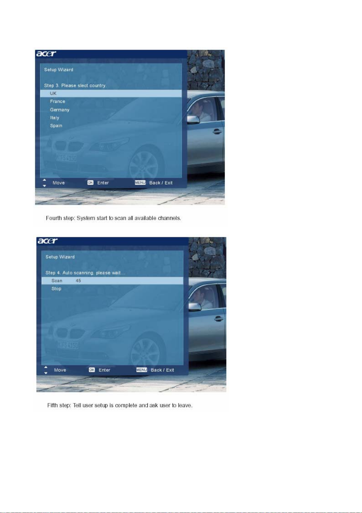
z15 pin D-Sub for VGA
z24 pin DVI / HDCP for DVI-D
zDIN45325 ( IEC169-2 ) Terminal for TV / CATV input
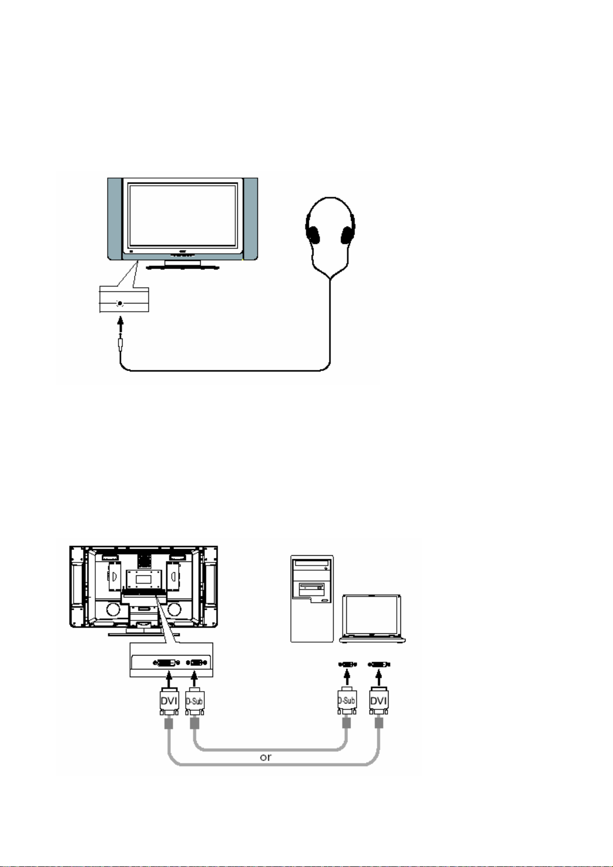
z3.5 mm∮Earphone jack for Audio Line input
z3.5 mm∮Earphone jack for Audio Line output
Video Functions
zSupport PAL / NTSC / SECAM video format
zSupport 480i/576i, 480p/576p, 1080i and 720p format
zBuild in Teletext functions
zBuild in Dynamic adaptive smoothing filter
zBuild in Dynamic temporal frame-filtering Noise Reduction

zBuild in Dynamic motion and edge adaptive De-interlacing
zFilm mode 3:2 & 2:2 pull down
zScreen display model 16:9 / 4:3 / panorama / zoom / PIP / POP
Mechanical
zSwivel: 40° ( R: 20°, L: 20° )
zVESA mounting holes
Compatibility
Multi-Sound system
zNICAM
zFM Stereo ( A2 )
Power Source
zInput voltage: 90 ~ 264 V, 47 ~ 63 Hz
zInput current: 2.3 A
zPower consumption: 210 Watts
zStand-by: 5 Watts Max.
Remote controllers
zMulti-function remote controller
Speaker
zInternal speaker: 10 W x 2 stereo, volume adjustable
Others
zOn screen display adjustment function
●ISP ( In System Programming ) function available for revising driver easily

Block Diagram
System Block & Wiring Diagram
I/O Board
Scart YUV
Scart RGB
Tuner
SPEAKER-
Recever
IR Key Boar
d
I/O Board
Second
SPEAKER-
S Video IN
CVBS IN
YUV IN
INVERTE
R
PANEL
Board
A
UDIO
Board
POWER
M
AIN Board

LCD Main Board Block Diagram

Basic Connection
Connecting the power cord
1. Plug the AC cord into the AC input on the back of the set.
2. Connect the male plug to the wall outlet as shown.
Connecting an antenna
Plug the outdoor antenna cable lead-into the antenna terminal on the back of the TV set
as shown.

Connecting DVD/VCR/AV equipment
Connect the SCART cable to the SCART port as shown below.
Connecting a camera, camcorder or video game
Connect your camera or camcorder to the Video/Audio ports on the bottom of the TV
set as shown below.

Connecting headphones
Connect your headphones to the headphone input port on the bottom of the TV set as shown below.
Connecting a PC or Notebook
Connect your PC or notebook to the D-Sub or DVI ports on the bottom of the TV set as
shown below.

OSD(On Screen Display)
Scanning the channels
First step: Ask user to select the language of OSD.


Advanced Features
PIP/PBP/POP
PIP (Picture in Picture)
PBP (Picture by Picture)

POP (Picture on Picture)

Acer Emowering Feature
Favorite Channel
Scenario Mode
No matter OSD menu is on or off, user can directly switch the scenario
mode. If OSD menu is on, switching scenario mode doesn’t cause the menu
off and user can see the related parameters directly on the menu.

Display Electrica
l and Functional Specifications
Input and Output Signals
This LCD TV shall have the ability to operate under following range with stable green color
of LED indicated. Any signal outside of the limits ( any combination ) shall not cause any
damage to the unit or driving source. The range of operation is:
zCVBS and Y/C
PAL ( 4.43 M , 50 Hz ) B、G、D、K、H、I, PAL ( 4.43 M , 60 Hz )
SECAM D、K 、L
NTSC ( 3.58 M ), NTSC ( 4.43 M ), Japan ( 50 Hz )
zTV Systems
PAL and SECAM system Receivable
Full frequency range From channel E2 ( 48.25 MHz ) to channel E69 ( 855.25
MHz )
zYUV inputs
YCbCr ( 480i/576i )
YPbPr ( 480p/576p、1080i、720p )
zVGA and DVI-D inputs
Horizontal input frequency range: 30 KHz to 70 KHz
Verticalinputfrequencyrange: 56 Hz to 85 Hz
Max. Resolution: 1360 x 768
Down Scaling support: 1152 x 870 75 Hz
1280 x 960 60 / 85 Hz
1280 x 1024 60 / 75 / 85 Hz
The LED shall indicate green color and OSD will show “ Out of Range “ message within 5
seconds after signal is out of range or down scaling support from selected input.

This LCD TV shall catch signal sources from TV、AV1、AV2、AV3、AV4、AV5、VGA and
DVI-D automatically during power up, which it is unnecessary to select inputs from OSD or
hot keys.
The priority to catch signal sources shall be 1st) User selected source from hot key or OSD,
2nd) Last source used, 3rd) TV input ( last power down channel ), 4th) AV1 RGB input, 5th) AV1
S-video input, 6th) AV1 CVBS input, 7th) AV2 YUV/RGB input, 8th) AV2 S-video input, 9th)
AV2 CVBS input, 10th) AV3 input ( Set to be input from OSD ), 11th) AV4 YUV input, 12th)
AV4 S-video input, 13th) VGA input, 14th) DVI-D input. The LCD TV shall complete selection
and show media on screen within 5 seconds ( including Auto Adjust ).
The LED shall indicate green color and OSD will show “ No Signal “ within 3 seconds while
there is missing signal from selected input.
The LED shall indicate green color and OSD will show “ No VGA Connection “ within 5
seconds while VGA input is selected but has no connection on VGA port.
The LED shall indicate green color and OSD will show “ Go Into Power Save “ within 5
seconds after meet condition of power saving mode.
This LCD TV shall go into power saving state in 5 seconds later of showing “ Go Into
Power Save “. The LED shall indicate amber color during power saving mode.
This LCD TV shall proceed Auto Adjust while VGA or DVI-D input is selected and 1)
Power up, 2) Auto Adjust pressed from OSD, 3) Factory preset acted, 4) New mode is detected.
Auto adjust shall be completed within 3 seconds.
The AV1 input supports RGB, S-video and CVBS video inputs. If the RGB, S-video and
CVBS video inputs are connected with cables, the priority shall be 1st) RGB input, 2nd) S-video
input, 3rd) CVBS video input.
The AV2 input supports YUV/RGB, S-video and CVBS video inputs. If the YUV/RGB,
S-video and CVBS video inputs are connected with cables, the priority shall be 1st) YUV/RGB
input, 2nd) S-video input, 3rd) CVBS video input.
The AV3 input support YUV.
The AV4 could be set either input or output from OSD. While it is set to be output, AV3
would carry CVBS signal and stereo audio out from TV tuner.
The AV5 input supports S-video

Chapter 3 45
This chapter contains step-by-step procedures on how to disassemble the LCD TV for maintenance and
troubleshooting.
To disassemble the TV, you need the following tools:
TWrist grounding strap and conductive mat for preventing electrostatic discharge
TSmall Philips screw driver
TPhilips screwdriver
TPlastic flat head screw driver
TTweezers
NOTE: The screws for the different components vary in size. During the disassembly process, group the
screws with the corresponding components to avoid mismatch when putting back the components.
When you remove the stripe cover, please be careful not to scrape the cover.
Chapter 3
Machine Disassembly and Replacement

46 Chapter 3
General Information
Before You Begin
Before proceeding with the disassembly procedure, make sure that you do the following:
1. Turn off the power to the system and all peripherals.
2. Unplug the AC adapter and all power and signal cables from the system.
3. Remove the battery pack.
NOTE: There are several types of screws used to secure the product. The screws vary in length. Please refer
the picture below, group the same type of screws together during service disassembling. Please also
remember the screw location for each screw type. If you fasten the screw to the wrong location, the
screw may be too long to damage the main board.

Chapter 3 47
Disassembly Procedure
Removing the TV Stand Module
1. Remove the four screws securing the TV stand cover.
2. Remove the TV stand cover.
3. Remove the six screws securing the TV stand module.
4. Remove the TV stand module.
5. Remove the four screws securing the base.
6. Separate the base and the swivel assembly.
Remving the I/O and Media Box
1. Remove the two screws securing the I/O box.
2. Remove the I/O box.
3. Remove the two screws securing the media box.
4. Remove the media box.
Removing the Speakers
1. Remove the three screws securing left speaker.
2. Disconnect the left speaker cable.
3. Remove the left speaker.
4. Remove the three screws securing right speaker.

48 Chapter 3
5. Disconnect the right speaker cable.
6. Remove the right speaker.
7. Remove the eight screws securing the speaker rear cover.
8. Remove the speaker rear cover.
9. Remove the four screws securing the speaker front cover.
10. Remove the speaker front cover.
Removing the System Fan
1. Remove the four screws securing the fan cover.
2. Remove the fan cover.
3. Remove the system fan.
Removing the Wall Mount Assembly
1. Remove the sixteen screws securing the back cover.
2. Remove the back cover.
3. Remove the eight screws securing the wall mount assembly.
4. Remove another eight screws securing the sall mount assembly.
5. Remove the four screw nuts securing the wall mount as shown.

Chapter 3 49
6. Lift the wall mount up and slide it out.
Removing the Power Board
1. Disconnect the cables from power board.
2. Remove the three screws securing the power board.
3. Remove the other three screws securing the power board.
4. Remove the power board.
Removing the Audio Board and the Main Board
1. Disconnect all cables connected to the audio board.
2. Remove the four screws securing the audio board.
3. Remove the audio board.
4. Remove the two screws securing the mainboard.
5. Remove the other four screws securing the mainboard.
6. Detach the main board from the unit.
Removing the Interface Board
1. Remove the two screws securing the interface board.
Other manuals for AT3201W
2
Table of contents
Other Acer LCD TV manuals