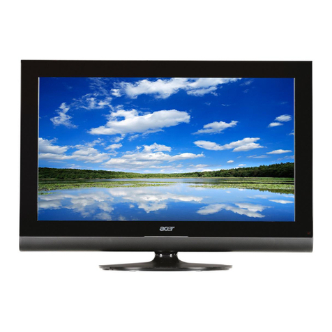
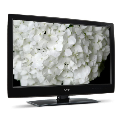
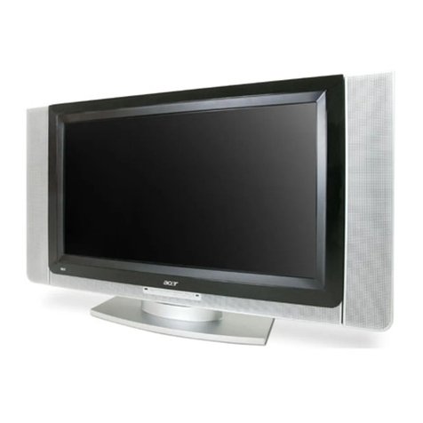
Acer AT2701W User manual

1
Acer AT2701W
Service Guide

2
Service Guide Version and Revision
No.
Version
Release Date
Revision
1
A00
Aug-02-2005
Original release

3
Copyright
Copyright 2003 Acer Technology Corp.
All rights reserved.
This manual may not, in whole or in part, be copied, photocopied, reproduced, translated, or converted to any
electronic machine readable form without prior written permission of Acer Technology Corp.
ACER AT2701W Service Manual.
Printed in Fujian.
Disclaimer
The information in this guide is subject to change without notice. Acer Incorporated makes no representations
or warranties, either expressed or implied, with respect to the contents hereof and specifically disclaims any
warranties of merchantability or fitness for any particular purpose. Any Acer Incorporated software described
in this manual is sold or licensed "as is". Should the programs prove defective following their purchase, the
buyer (and not Acer Incorporated, its distributor, or its dealer) assumes the entire cost of all necessary
servicing, repair, and any incidental or consequential damages resulting from any defect in the software.
Acer is a registered trademark of Acer Corporation.
Intel is a registered trademark of Intel Corporation.
Pentium and Pentium II/III are trademarks of Intel Corporation.
Other brand and product names are trademarks and/or registered trademarks of their respective holders.
Trademarks
All other trademarks are property of their respective owners.
Conventions
The following conventions are used in this manual:
Screen messages
Denotes actual messages that appear on screen.
NOTE
Gives bits and pieces of additional information related to the current topic.
WARNING
Alerts you to any damage that might result from doing or not doing specific
actions.
CAUTION
Gives precautionary measures to avoid possible hardware or software
problems.
IMPORTANT
Remind you to do specific actions relevant to the accomplishment of
procedures.
Preface
Before using this information and the product it supports, please read the following general information.
1. This Service Guide provides you with all technical information relating to the BASIC CONFIGURATION
decided for Acer's "global" product offering. To better fit local market requirements and enhance product
competitiveness, your regional office may have decided to extend the functionality of a machine (e.g.
add-on card, modem, or extra memory capability). These LOCALIZED FEATURES will NOT be covered in
this generic service guide. In such cases, please contact your regional offices or the responsible
personnel/channel to provide you with further technical details.
2. Please note WHEN ORDERING FRU PARTS, that you should check the most up-to-date information
available on your regional web or channel. If, for whatever reason, a part number change is made, it will not

4
be noted in the printed Service Guide. For ACER-AUTHORIZED SERVICE PROVIDERS, your Acer office
may have a DIFFERENT part number code to those given in the FRU list of this printed Service Guide. You
MUST use the list provided by your regional Acer office to order FRU parts for repair and service of
customer machines.
Warning: (For FCC Certified Models)
Note: This equipment has been tested and found to comply with the limits for a Class B digital device,
pursuant to Part 15 of the FCC Rules. These limits are designed to provide reasonable protection against
harmful interference in a residential installation. This equipment generates, uses and can radiate radio
frequency energy, and if not installed and used in accordance with the instructions, may cause harmful
interference to radio communications. However, there is no guarantee that interference will not occur in a
particular installation. If this equipment does cause harmful interference to radio or television reception, which
can be determined by turning the equipment off and on, the user is encouraged to try to correct the
interference by one or more of the following measures:
1. Reorient or relocate the receiving antenna.
2. Increase the separation between the equipment and receiver.
3. Connect the equipment into an outlet on a circuit different from that to which the receiver is connected.
4. Consult the dealer or an experienced radio/TV technician for help.
Notice:
1. The changes or modifications not expressly approved by the party responsible for compliance could void
the user's authority to operate the equipment.
2. Shielded interface cables and AC power cord, if any, must be used in order to comply with the emission
limits.
3. The manufacturer is not responsible for any radio or TV interference caused by unauthorized modification
to this equipment. It is the responsibility of the user to correct such interference.
As ENERGY STARPartner our company has determined that this product meets the ENERGY STAR
guidelines for energy efficiency.
Warning:
To prevent fire or shock hazard, do not expose the monitor to rain or moisture. Dangerous high voltages
are present inside the monitor. Do not open the cabinet. Refer servicing to qualified personnel only.

5
Precautions
Do not use the monitor near water, e.g. near a bathtub, washbowl, kitchen sink, laundry tub, swimming pool
or in a wet basement.
Do not place the monitor on an unstable trolley, stand, or table. If the monitor falls, it can injure a person
and cause serious damage to the appliance. Use only a trolley or stand recommended by the manufacturer
or sold with the monitor. If you mount the monitor on a wall or shelf, uses a mounting kit approved by the
manufacturer and follow the kit instructions.
Slots and openings in the back and bottom of the cabinet are provided for ventilation. To ensure reliable
operation of the monitor and to protect it from overheating, be sure these openings are not blocked or
covered. Do not place the monitor on a bed, sofa, rug, or similar surface. Do not place the monitor near or
over a radiator or heat register. Do not place the monitor in a bookcase or cabinet unless proper ventilation
is provided.
The monitor should be operated only from the type of power source indicated on the label. If you are not
sure of the type of power supplied to your home, consult your dealer or local power company.
The monitor is equipped with a three-pronged grounded plug, a plug with a third (grounding) pin. This plug
will fit only into a grounded power outlet as a safety feature. If your outlet does not accommodate the
three-wire plug, have an electrician install the correct outlet, or use an adapter to ground the appliance
safely. Do not defeat the safety purpose of the grounded plug.
Unplug the unit during a lightning storm or when it will not be used for long periods of time. This will protect
the monitor from damage due to power surges.
Do not overload power strips and extension cords. Overloading can result in fire or electric shock.
Never push any object into the slot on the monitor cabinet. It could short circuit parts causing a fire or
electric shock. Never spill liquids on the monitor.
Do not attempt to service the monitor yourself; opening or removing covers can expose you to dangerous
voltages and other hazards. Please refer all servicing to qualified service personnel
To ensure satisfactory operation, use the monitor only with UL listed computers which have appropriate
configured receptacles marked between 100 - 240V AC, Min. 5A.
The wall socket shall be installed near the equipment and shall be easily accessible.
Special Notes On LCD TV Monitors
The following symptoms are normal with LCD TV monitor and do not indicate a problem.
Notes
Due to the nature of the fluorescent light, the screen may flicker during initial use. Turn off the Power Switch
and then turn it on again to make sure the flicker disappears.
You may find slightly uneven brightness on the screen depending on the desktop pattern you use.
The LCD TV screen has effective pixels of 99.99% or more. It may include blemishes of 0.01% or less such
as a missing pixel or a pixel lit all of the time.
Due to the nature of the LCD TV screen, an afterimage of the previous screen may remain after switching
the image, when the same image is displayed for hours. In this case, the screen is recovered slowly by
changing the image or turning off the Power Switch for hours.

6
Table Of Contents
Chapter 1
Monitor Features
………………………………………
7
General specifications
………………………………………
7
LCD TV description
………………………………………
8
Interface Connector
………………………………………
8
Precautions and notices
………………………………………
8
D-SUB PIN distribution
………………………………………
10
Factory Preset Display Modes
………………………………………
11
LCD TV Panel Specification
………………………………………
12
Panel Features
………………………………………
12
General specifications
………………………………………
12
Mechanical specifications
………………………………………
12
Optical specifications
………………………………………
13
Chapter 2
Connecting Peripherals
………………………………………
14
Front Panel controls
………………………………………
14
Operating instrustions
………………………………………
14
Chapter 3
Remote Control & OSD Operating
instructions
………………………………………
17
Using the OSD Menus
………………………………………
21
LOGO
………………………………………
25
Chapter 4
Machine Disassembly
………………………………………
26
Chapter 5
Software Flow Chart
………………………………………
33
Chapter 6
Trouble Shooting
………………………………………
36
Chapter 7
White-Banance,Luminance adjustment
………………………………………
42
Chapter 8
FRU ( Field Replaceable Unit ) List
………………………………………
45
Exploded Diagram
………………………………………
46
EDID Data
………………………………………
47
Chapter 9
PCB Layout
………………………………………
48
Chapter 10
Schematic Diagram
………………………………………
51

7
Monitor Features
GENERAL SPECIFICATIONS
Items
Specification
LCD Panel
Screen Size
27” TFT-LCD
Aspect Ratio
16: 9
Resolution
1366 x 768 pixels
TV Function
TV Tuning System
PAL B/G, D/K, I and SECAM L/L’ (Multi-Europe)
Full Channel with Electronic PLLTuner
Sound System
Nicam / A2
Teletext
Yes (252 Page)
Color systems
PAL / SECAM / NTSC
PC Input
Signal Input
Analog: D-Sub 15 pin (detachable cable)
PnP compatibility
DDC 2B
Recommended Analog
1024 x 768 (60Hz)
Input Audio
Headphone Mini-jack for stereo (3.5ø)
Audio Output
Audio Output: L / R
Speaker (built-in): Two 5 watt speakers
Headphone Mini-jack for stereo (3.5ø)
Line Output (SCART L/R)
Other Function
PIP (only when in PC mode)
Table Stand
Included
Wall Mount
VESA 100 x 100 mm
Power
Power Supply
AC100V~240V, 50/60Hz
Power Consumption
<140W
Panel Tilt
Forwards/ Backwards/ Rotation
-5°/ +20°/ ±30°
Dimension
W x H x D (with stand)
898 x 470 x 287 (mm)
Weight (net)
Kg (w/o Accessories)
13.4 KG
Accessories
Remote Control, Batteries (x2), AC Power Cord, Composite Cable, SCART Cable,
S-Video Cable, User’s Guide
AV1(SCART1)
SCART (CVBS & RGB , Audio L/R)
AV2/SCART2
SCART (CVBS, Audio L/R)
AV3
RCA for CVBS, Audio L/R
AV3-S
S Din For S-Video, Audio L/R share with RCA
Chapter 1

8
LCD TV DESCRIPTION
The LCD TV will contain a main board (include audio), a switching power board (include an inverter
board), an IR board, a function keyboard, a DPF Board and an Ear phone board. The main board and
power board will house the flat panel to control logic I2C bus, DDC, brightness control logic for LCD
panel, DC-DC conversion to supply the appropriate power to the whole board and transmitting TTL
level signals into LCD Module to drive the LCD display circuit.
The inverter board will drive the sixteen CCFLs (Cold Cathode Fluorescent Tube).
The switching power board will provides the power ON/OFF to control the TV and control LED indicator
for DPMS.
The function keyboard and Remote Control will provide the OSD control signal to the Main Board.
INTERFACE CONNECTOR
A : Power Cord Connector.
B : RF Signal Connector.
C : Video / Audio Signal Connectors.
D : PC D-sub 15 pin Connector.
E : PC Audio Connector.
PRECAUTIONS AND NOTICES
1-1 ASSEMBLY PRECAUTION
(1) Please do not press or scratch LCD panel surface with anything hard. And do not soil LCD panel
surface by touching with bare hands (Polarize film, surface of LCD panel is easy to be flawed)
In the LCD panel, the gap between two glass plates is kept perfectly even to maintain display
characteristic and reliability. If this panel is subject to hard pressing, the following occurs :
(a) Uniform color (b) Orientation of liquid crystal becomes disorder
(2) Please wipe out LCD panel surface with absorbent cotton or soft cloth in case of it being soiled.
(3) Please wipe out drops of adhesive like saliva and water in LCD panel surface immediately.
They might damage to cause panel surface variation and color change.
(4) Do not apply any strong mechanical shock to the LCD panel.

9
1-2 OPERATING PRECAUTION
(1) Please be sure to unplug the power cord before remove the back-cover. (be sure the power is
turn-off)
(2) Please do not change variable resistance settings in MAIN-BOARD; they are adjusted to the most
suitable value. If they are changed, it might happen LUMINANCE does not satisfy the white
balance spec.
(3) Please consider that LCD backlight takes longer time to become stable of radiation characteristic in
low temperature than in room temperature.
(4) Please pay attention to displaying the same pattern for very long-time. Image might stick on LCD.
1-3 STORAGE PRECAUTION
(1) When you store LCD for a long time, it is recommended to keep the temperature between 0°C
-40°C without the exposure of sunlight and to keep the humidity less than 85% RH.
(2) Please do not leave the LCD in the environment of high humidity and high temperature such as
60°C, 85%RH.
(3) Please do not leave the LCD in the environment of low temperature; below -25°C.
1-4 HIGH VOLTAGE WARNING
The high voltage was only generated by Power support part, if carelessly contacted the transformer
on this module, can cause a serious shock.

10
D-SUB PIN DISTRIBUTION
This procedure gives you instructions for installing and using the LCD TV display.
(1) Position the display on the desired operation and plug the power cord into a convenient AC
outlet.Three-wire power cord must be shielded and is provided as a safety precaution as it
connects the chassis and cabinet to the electrical conduct ground. If the AC outlet in your
location does not have provisions for the grounded type plug, the installer should attach the
proper adapter to ensure a safe ground potential.
(2) Connect the 15-pin color display shielded signal cable to your signal system device and lock both
screws on the connector to ensure firm grounding. The connector information is as follow:
15 - Pin Color Display Signal Cable
PIN NO.
DESCRIPTION
PIN NO.
DESCRIPTION
1
Red Video
9
No Pin!
2
Green Video
10
Sync Ground
3
Blue Video
11
Not Used
4
Not Used
12
Serial Data for DDC
5
Ground
13
H-Sync.
6
Red Ground
14
V-Sync.
7
Green Ground
15
Serial Clock for DDC
8
Blue Ground
(3) S-Video ( Y /C ): TV rear side : 4 pin Mini-DIN female
SCART: TV rear side : RCA female
TV: TV rear side : IEC type female
AV1 : TV rear side : RCA female (Yellow )
Audio: TV rear side : RCA female (Red / White )
PC Input audio: 3.5mm Stereo female
Audio Input for AV1,S-Video, SCART Video : RCA female ( Red / White )
Headphone : 3.5mm female
Audio line Out ( to another speaker ) : RCA female ( Red / White )
(4) Apply power to the display by turning the power switch to the "ON" position and allow about ten
seconds for Panel warm-up. The Power-On indicator lights "GREEN" when the display is on.
1
6
11
15
5
10

11
(5) With proper signals feed to the display, a pattern or data should appear on the screen, adjust the
brightness and contrast to the most pleasing display, or press auto-adju to get the best
picture-quality.
(6) This TV (with PC function) has power saving function following the VESA DPMS. Be sure to connect
the signal cable to the PC.
(7) If your TV requires service, it must be returned with the power cord.
Factory Preset Display Modes:
Analog RGB Signal Timing
Dots ×Lines
Vertical
Horizontal
Sync Polarity
Presence
Screen Mode
Frequency
Frequency
Horizontal
Vertical
Horizontal
Vertical
Normal
FULL
(Hz)
(kHz)
(4:3)
(16:9)
720×400
70.1
31.5
NEG
POS
YES
YES
YES
YES
640×480
59.9
31.5
NEG
NEG
YES
YES
YES
YES
75.0
37.5
NEG
NEG
YES
YES
YES
YES
800x600
75.0
46.9
POS
POS
YES
YES
YES
YES
1024×768
60.0
48.4
POS
POS
YES
YES
YES
YES
1280×768
60.0
47.7
NEG
POS
YES
YES
YES
YES

12
LCD TV Panel Specification
PANEL FEATURES
- Excellent brightness (550 nits)
- Ultra high contrast ratio (1000:1)
- Fast response time (8ms)
- High color saturation NTSC 75%
- WXGA (1366 x 768 pixels) resolution
- DE (Data Enable) only mode
- LVDS (Low Voltage Differential Signaling) interface
- Optimized response time for both 50/60 Hz frame rate
- Ultra wide viewing angle: 176(H)/176(V) (CR>20) Super MVA technology
- 180 degree rotation display option
GENERAL SPECIFICATI0NS
MECHANICAL SPECIFICATIONS

13
Optical Specifications

14
Connecting Peripherals
Front panel controls
Power Key:Press to turn the LCD TV on or off.
MENU Key:Press to show and exit the OSD menu.
Down / Up Key:Press to perform function and channel selection.
- / + Key:Press to adjust the volume level, or confirm function selection.
Input Key:Press to select your input source.
Operating Instructions
The following front panel adjustments are available for this product. For details on the locations of these
adjustments.
POWER switch: This switch shall be visible and accessible on the down right side of front PC frame. Soft
Power Switch (TURN ON SYSTEM) and one push of Soft-Power Switch shall turn on the system.
Note: This switch is not considered the “Mains Disconnection Device” for agency purposes. The AC switch in
back cover of product can also disconnect power. The power cord is the main disconnection device.
Power Indicator LED KEY: This LED will illuminate “Green” light when the product is ON and “Orange” light
when the product in stand-by mode.
CH +/- KEY: These two switches shall be visible and accessible on the bottom of front panel control keys.
While TV is selected as input source, activation of these keys will cycle through all available TV channels.
While OSD menu is up, activation of these keys will highlight each available adjustment. The activation time
for this switch includes Press and Hold should be less than half second.
VOL +/- KEY: These two switches shall be visible and accessible on the bottom of front panel control keys.
Activation will increase /decrease loudness of the audio output. In addition, while OSD menu is up, activation
of these keys will regulate a pre-selected adjustment. The activation time for this switch includes Press and
Hold should be less than half second.
MENU KEY: This switch shall be visible and accessible on the left side of VOL - switches. Once pressed,
this key shall bring up the corresponding OSD menu(s) based on the selected input source.
INPUT KEY: This switch shall be visible and accessible on the right side of VOL + switches. Once pressed,
this key shall toggle in a closed loop of the input source selection from TV, AV1, AV2, AV3, AV3-S and PC.
Headphone: This connector is designed purpose to use headphone. Once the headphone connected, then
the speakers will auto mute on audio output.
Chapter 2

15
There is a wide range of devices that can be connected to your LCD TV. Please refer to the section below:
Preparation
Remove the back plate of the TV as shown above.If you lay your LCD TV flat on a table, with the screen facing
down, it will be easier to connect your peripheral equipment. Be careful not to damage the screen.
How to connect

16
Headphone
1、When you attach headphones, the speakers built into your TV set will be disabled. You can use the VOL
controls on the TV set or remote control to adjust the volume level.
2、Press the key on the remote control to switch off the sound from the headphone.
PC
How to connect PC input
1. Use the D-sub cable in the accessories box, and plug it into the D-sub port located beneath the TV screen.
2. Use the audio cable in the accessories box, and plug it into the PC’s audio jacks and the audio jack located
beneath the TV screen.

17
Remote Control & OSD Operating instructions
Using the Remote Control
Chapter 3

18

19

20
TELETEXT
Teletext is a text-based information service provided by some TV stations, in addition to traditional TV
broadcasts.
Table of contents
Other Acer LCD TV manuals