1. Product Specification (continued)
1.3.3 User Controls and Indicators
1.3.3.1 Power On / Off Switch
The monitor shall have a power control switch
visible and accessible on the front of the monitor .
The switch shall be marked with icons per IEC 417
, # 5007 and # 5009.The switch shall interrupt the
DC supply to the monitor.
1.3.3.2 Power Indicator LED
The monitor shall make use of an LED type
indicator located on the front of the monitor .
The LED color shall indicate the power states as
given in Table 1.
Function LED Color
Full Power Blue color
Sleep Orange color
Table 1
1.3.3.3 On-Screen Display
The Wistron On Screen Display system shall be
used, controlled by a Menu button. If the buttons
remain untouched for OSD turn off time while
displaying a menu, the firmware shall save the
current adjustments and exit. Also, if the video
controller changes video mode while the OSD is
active, the current settings shall be saved
immediately, the OSD turn off, and new video
mode is displayed.
ITEM CONTENT
AUDIO VOLUME To increase or decrease the sound level
BRIGHTNESS Back light Luminance of the LCD panel is adjusted.
CONTRAST A gain of R , G and B signal is adjusted.
AUTO CONTRAST A gain of R , G and B signal auto adjust.
CLOCK The ratio of dividing frequency of the dot clock is adjusted.
PHASE The phase of the dot clock is adjusted.
H-POSITION The indication screen is horizontally moved right and left (1 Pixels pitch).
V-POSITION The indication screen is vertically moved up and down (1 Pixels pitch).
AUTO ADJUST Clock system auto adjustment, about under 8 sec.
COLOR BALANCE Select three kinds of modes. ( USER /WARM / Cold ).
OSD POSITION The OSD indication position can be adjusted.
OSD LANGUAGE
Select the language used for the OSD menu among English , French ,
Italian , Deutsch and Spanish.. . . .EMEA. . .
RECALL DEFAULTS All data copy from factory shipment data.
OSD DURATION Adjust OSD menu off time range from10~120 second.
POWER-SAVE Back light of the LCD panel is cut when the signal is not input (AC line
power consumption 2W or less).
INFORM ATION The frequency of the horizontal / vertical synchronizing signal under the
input is indicated.
※NOTE : OSD MENU SEE APPENDIX A
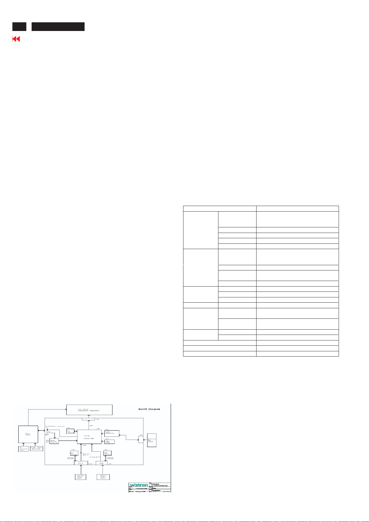
1.3.4 Monitor Modes and Timing Capability
1.3.4.1 Format and Timing
The monitor shall synchronize with any vertical
frequency from 55 to 61 Hz , and with any
horizontal frequency from 30 to 76KHz. If the input
frequency is out of the above – specified range,
the monitor shall display a warning screen
indicating that the input frequency is out of range.
Under no circumstances shall any combination of
input signals cause any damage to the monitor .
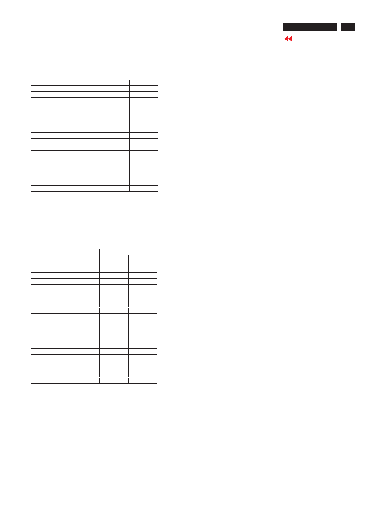
1.3.4.2 Factory Assigned Display Modes
There are 18 factory pre-set frequency video
modes. These modes have a factory pre-set
for all characteristics affecting front-of-screen
performance. When the system is powered
on, previously stored screen parameters for a
pre-defined mode will be recalled if the
operating mode is one of those stored in
memory. If the operating mode is not one of
those stored in memory, the monitor CPU will
select the PRESET timing for a mode that is
the next lowest in horizontal scanning
frequency to the mode being currently used.
The screen parameters may be adjusted by
the use of the front bezel controls and then
may be saved as a user defined mode. The
monitor shall include all the preset video
timings shown in the following page.( Please
see Note. (3) )
1.3.4.3 Mode Recognition Pull-in
The monitor shall recognize preset modes
within a range of 1KHz whichever is less for
horizontal ; and within 1Hz for vertical.
1.3.4.4 User Display Modes
In addition to the factory pre-set video modes,
provisions shall be made to store up to 9 user
modes. If the current mode is a user mode, the
monitor shall select its previously stored
settings. If the user alters a setting, the new
setting will be stored in the same user mode.
The user modes are not affected by the pre-set
command. If the input signal requires a new
user mode, storage of the new format is
automatically performed during user
adjustment of the display (if required).( Please
see Note.(4) )
4
Go to cover page
ACER V233H