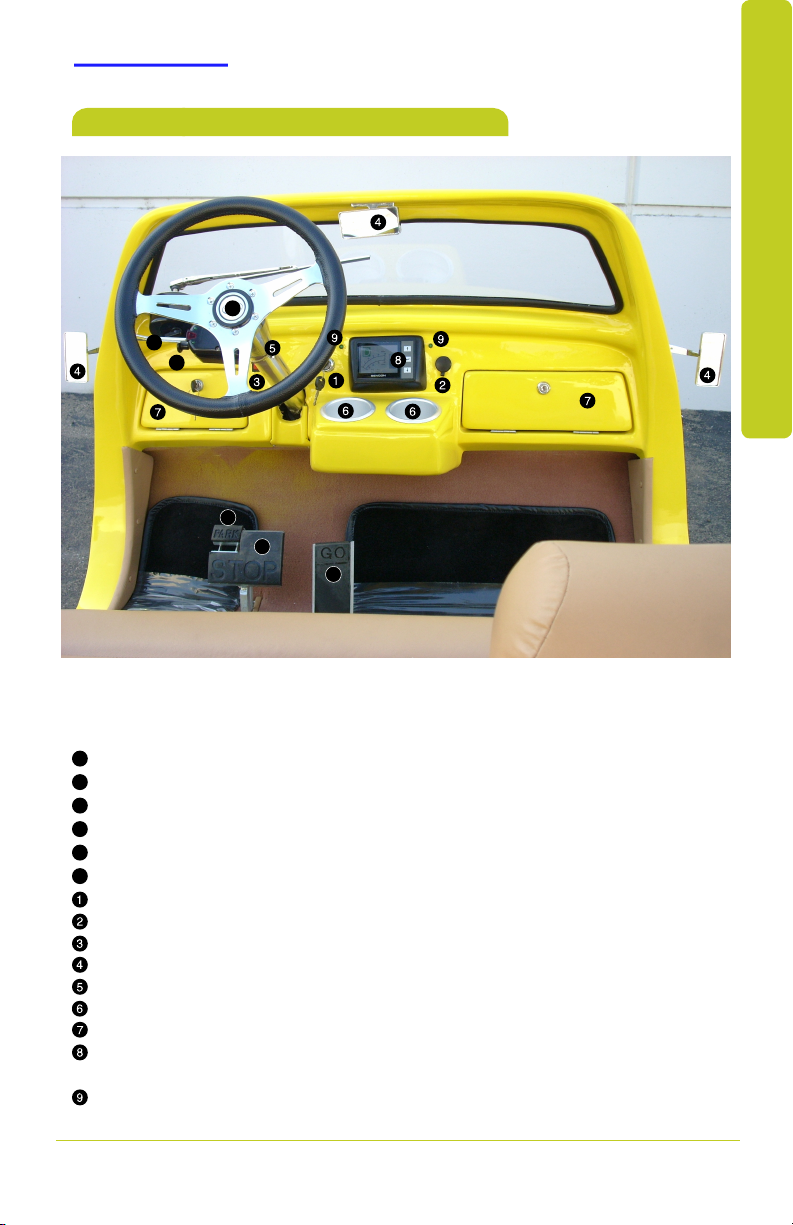
ACG 39 Roadster 2016 User manual

2016 ACG
3399RRooaaddsstteerr
Quick Reference Guide

A word about safe vehicle operation
This Quick Reference Guide is not a full description of vehicle
operations. Every owner or operator should review completely
the Owner’s Manual that accompanies this vehicle.
All information in this Quick Reference Guide is current at the
time of printing. ACG reserves the right to make changes at any
time without notice.
Pay special attention to the boxed information highlighted in
color throughout the Owner’s Manual. Each box contains safety
operating instructions to help you avoid injury or equipment
malfunction or damage.
The latest version of both the Owner’s Manual and this Quick
Reference Guide is posted on ACG website: www.acgcars.us
This Quick Reference Guide is a summary of basic vehicle operations.
It contains brief descriptions of fundamental operations so you can
locate and use the vehicle’s main equipment quickly and easily.
Your dealership and the entire staff of American Custom Golf Cars,
Inc. wish you many years of satisfied driving in your new vehicle.
We strongly encourage you to review the Owner’s Manual and any
supplementary manual so you will have a better understanding of
the vehicle’s capabilities and limitations.
The Quick Reference Guide is not intended as a substitute for the
Owner’s Manual.
2016 ACG
3399RRooaaddsstteerr

3
INDEX
FEATURES/OPERATION
SAFETY AND
EMERGENCY FEATURES
OVERVIEW
Instrument panel & Main controls 4
Drive Direction Switch 4
4
Indicator symbols 5
Instrument cluster 5
Light Switch
Drive Direction Switch
Main Key Switch
Parking Brake
Accelerator Pedal
Brake Pedal
Lights & turn signals
Multi-Information Display
Horn Button
Power outlet
Glove & Storage Boxes
Cup Holders
Windshield wiper
Seat belts 12
Tire Pressure Information label 12
OVERVIEW FEATURES/OPERATIONS SAFETY AND EMERGENCY FEATURES
7
7
8
8
9
9
7
10
11
11
11
11
Vehicle maintenance 5
6Battery Percent Charge Information

4
OVERVIEW
Instrument panel & Main controls
Main Key Switch (OFF-ON)
Power outlet 12V DC
Headlight Switch (ON-OFF)
Mirrors
Steering column
Cup Holders
Glove Box
Display Screen
Display Screen Control Buttons
Turn Signal Telltale LED Lights
OVERVIEW
Horn Button
F
Hazard Switch
E
Turn Signal Lever
D
Parking Brake Pedal (PARK)
C
Brake Pedal (STOP)
B
Accelerator Pedal (GO)
A
A
BB
C
D
E
F

Drive Switch position indicator
Multi-Information Display
Speedometer
Service indicator and reminder
UP button
DOWN button
MODE button
Battery Charge %
Battery Charge Bar Graph
Turn Signal Telltale LED Lights
Trip meter
Odo meter Total miles traveled
See page 6 for
IMPORTANT INFORMATION
5
OVERVIEW
OVERVIEW
entry
NOTE:
Vehicle maintenance
Please refer to the “Warranty Maintenance Guide.”
Regularly scheduled maintenance will help extend the service life
of your vehicle and maintain its safety and performance.
Refer to the Owner’s Manual for more details.
Drive Switch is in NEUTRAL position (N)
Check Battery Fluid Level
Indicator symbols
For details, refer to Owner’s Manual.
.
N
R
D
Drive Switch is in REVERSE position (R)
Drive Switch is in DRIVE position (D)
CHECK
Multi-Information Display

6
OVERVIEW
IMPORTANT INFORMATION
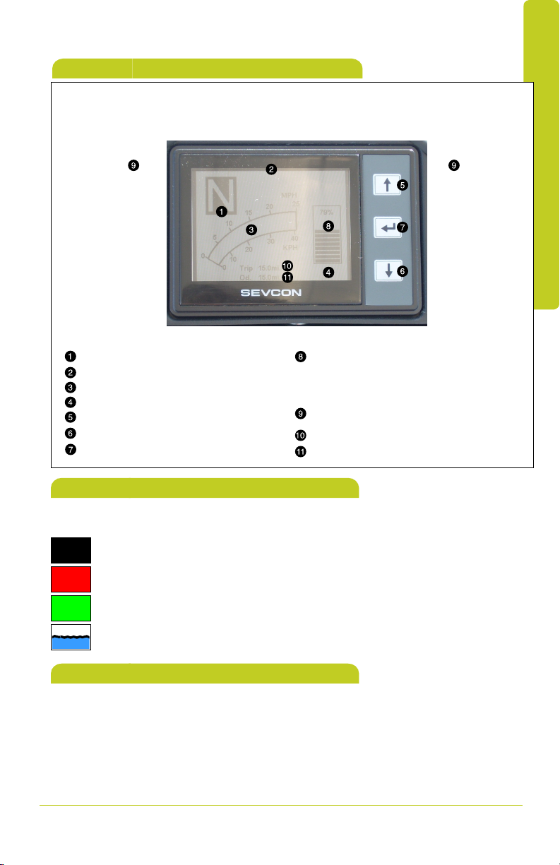
Battery Percent Charge Information on SEVCON Display
The Battery charge level indicates the relative state of charge of the
Traction Battery and NOT the remaining driving range of the vehicle.
Its algorithm is based on the PEAK Traction Battery Pack Voltage,
which in turn calculates the APPROXIMATE charge of the Traction
Battery.
The indicator may not always show 100% when the vehicle is first
turned on even if the On-Board Delta-Q charger indicates 100% or
full charge condition.
(Green LED ON – see Charging Procedure in Owne’r Manual for
more detail).
This condition is not a defect as the computerized “smart” Delta-Q
On-Board Charger may under certain conditions stop the charging
before achieving the maximum potential voltage.
The ambient and battery temperatures are monitored by the charger
and the charge cycle is automatically terminated based on internal
charge algorithm that is matched to the specific type of Battery,
which is used in your vehicle.
The charge algorithm is designed to maximize the battery life and to
prevent battery damage by overcharge.
Initially when the vehicle is FIRST driven after delivery or whenever
Traction Battery is serviced, the vehicle MUST be driven so that a
discharge level of 69% or less is achieved, and the Traction Battery
MUST BE FULLY CHARGED thereafter, in order for the State of
Charge bar graph indicator in the SEVCON Display to self reset to
100% indication.
If the Traction Battery is not deeply discharged (to below 69%) the
State of Charge will generally not indicate more than 80% even if the
On-Board Delta-Q Charger indicates FULLY Charged condition.
For long battery service life, the vehicle should not be operated
when the indicated Charge Level is 20% or less, and need not to be
re-charged if the Display Indication is 80% or more.
OVERVIEW

* The Drive Direction Switch must be in “N” and the brake pedal depressed
before the Main Key Switch is turned “ON”.
After the Display energizes and shows “N” turn the switch to “F” for FORWARD
travel or “R” for REVERSE.
Drive Switch position will be
indicated on the Display.
FEATURES/OPERATION
7
FEATURES/OPERATION
Drive Direction Switch
Parking brake
Reverse
Neutral*
Drive - Forward
R
N
D
N
S
ReleaseSet
Main Key Switch
Turn the Main Key Switch clockwise
to “ON” position;
turn counter-clockwise to “OFF”.
The Display will be active ONLY
when the Main Key Switch is “ON”.
BRAKE Depress the PARK section to Set. Depress the STOP section to Release.
Refer to the Owner’s Manual for more details.

FEATURES/OPERATION
FEATURES/OPERATION
8
Accelerator Pedal
Brake Pedal
Refer to the Owner’s Manual for more details.
Depress the STOP Pedal to reduce the vehicle speed,
slight pedal depression will activate the Electronically
controlled Regenerative Braking.
Further depression of the STOP Pedal will activate the
Hydraulic Braking System on both Front and Rear wheels.
Depress the GO Pedal to control the vehicle speed.

9
FEATURES/OPERATION
Windshield Wiper
Front
Wiper lever switch
Wipe ON
OFF
Lights & turn signals
Turn signals
Headlights & Taillights
Headlights ON
Taillights ON
Right turn
Left turn
FEATURES/OPERATION
Wiper lever switch is located at the center of the Windshield Wiper drive unit.
= Lights OFF

10
FEATURES/OPERATION
Horn button
The Horn Button is located at the center of the Steering Wheel,
depress the Button if audio warning is required during vehicle operation
(see above).
It is also identified by the ACG logo.
SAFETY AND EMERGENCY FEATURES
Hazard Lights Switch
The Hazard Warning Flasher Switch activates both Turn Signals to provide “Hazard Warning” by
flashing both Right and Left as well as Front and Rear Turn Signals at the same time.
The “Hazard” function is activated by Pull Switch located on Left side of steering column below
Steering Wheel. And immediately below the Turn Signal Lever.
It is a 2 position switch.
OFF - When the Pull Switch is released (pushed INWARD)
ON - When the Pull Switch is pulled out, the Turn Signal lights are activated.
NOTE:
The Hazard function can be canceled ONLY by moving the “Turn Signal Lever” from the the
horizontal “OFF” position to either “UP” (Right Turn) or “DOWN” (Left Turn) position!

11
FEATURES/OPERATION
Power outlet
Designed for car accessories.
Cup holders
Glove & Storage Boxes
FEATURES/OPERATION
Right SideLeft Side
12 Volt Power Outlet is located to the
right of Display on the Instrument Panel

12
SAFETY AND EMERGENCY FEATURES
If belt is fully extended, then retracted even slightly, it cannot be re-extended
beyond that point, unless fully retracted again. This feature is used to help hold
child restraint systems securely.
To find more information about seat belts, and how to install a child restraint
system, refer to the Owner’s Manual.
Keep as low on
hips as possible
Take up slack
Too high
Seat belts
Check/adjust each tire pressure daily.
Tire Pressure Information label
Refer to the load label located under driver seat or the Owner’s Manual for tire
inflation specifications.
Refer to the Owner’s Manual for more details.
SAFETY AND EMERGENCY FEATURES

NOTES
OVERVIEW FEATURES/OPERATION SAFETY AND EMERGENCY FEATURES

American Custom Golf Cars, Inc.
(ACG)
15740 El Prado Rd.
Chino, CA 91710 USA
(909) 597-2885
(909) 597-7183 fax
www.acgcars.us
Copyright © 2012-2015 American Custom Golf Cars, Inc.
ACG Logo
and
CCaalliiffoorrnniiaaRRooaaddsstteerr®
Are registered trademarks of American Custom Golf Cars, Inc.
This manual suits for next models
5
Table of contents
Popular Toy manuals by other brands

LEGO
LEGO 21120 Assembly instruction

Jotika
Jotika H.M. Brig Badger Assembly manual

Mattel
Mattel Barbie Doll Chelsea Birthday instructions

WARCRADLE STUDIOS
WARCRADLE STUDIOS DYSTOPIAN WARS TIANLONG BATTLEFLEET Assembly instructions

Max-Thrust
Max-Thrust Ryan STA Assembly and instruction manual

marklin
marklin Trix 16955 User manuals