ACI-AppliCAD TIF-102 Quick start guide

TIF-102 Telephone Interface
Installation and Use
ACI-AppliCAD, Inc.
LEVEL
POWER
CONNECT RING
TIF10
2
COMMENT
Version 1.3 1/1/16
Applies to serial # 110270100001 & above
(Also applies substantially to # 096610100001 & above)
www.aci-applicad.com


Table of Contents
Introduction ----------------------------------- 2
•Features & Benefits
•What’s In the Box
•FCC Information
Quick Start Guide --------------------------- 6
•Rear Panel Hookup
•Basic Operation
•Serving Your Remote Participant(s)
•Two-way Operation
•Directions For Those Calling In
Installation Guide --------------------------- 12
•Rear-Panel Diagram
•Telephone Jack
•Making Rear Panel Connections
•Wiring Relay Signal Contacts
•Using A Gated Microphone Mixer
•Adjusting Gain
Reference ------------------------------------- 17
•Troubleshooting
•How It Works
•Specifications
•Service and Warranty

2
Introduction
The T F-102 Telephone nterface extends listening to, and participating in, any
meeting over regular phone lines. Microprocessor control provides easy operation.
The T F-102 appears as an ordinary telephone set to your phone line, thus it’s as easy
to install as a telephone. Your Telephone Interface can ma e a real difference for a
participant who cannot be present, and it’s built to last.
Features and Benefits
TIF-102
Feature
What It Does
User Benefit
Two-Way Operation
The remote party can make
comments over their phone
Allows for remote participation as
well as listening
Recognition Request
with relay output
The remote user can get the
chairperson’s attention by
pressing their phone’s #key.
Phone comments need not be
arranged in advance!
Phone Line Release
Disconnects if the caller hangs up,
the connection drops, or after a
selectable three or 12 hours’
elapsed time.
Won’t needlessly tie up your phone
line and/or your conference
service. If your party gets
disconnected, they can call back.
Dual-Processor
Control System
Replaces seven individual ICs,
monitors all functions
Reliable operation and smart,
simple operating features.
LED Indicators
Show telephone line status and
audio level.
You know when audio is
transferring OK.
Compression
Manages your sound level, both
ways.
Provides comfortable listening.
Compress Output
for external FM Transmitter
Outputs a limited-level, 10mS
digital-delayed version of your
program.
Synchronized, consistent sound for
those listening with headphones.
New! 18 Pole, 3.8
KHz Digital Filter
s/n 110270100001 & above
(previously 11-pole, 3.5 KHz)
Our best sound quality possible
over a phone line.
FCC Approval
Tested to comply with FCC Rules,
Parts 15 & 68.
Approved and registered for use on
the telephone network.
Phone Line Surge
Protection
Protects against common surges
(No protector is 100% effective)
Reliable operation and long life.
External protector not required.
Receive-only mode
Provides phone reception from an
off-site program.
Your audience can hear a program
originating from another location.

3
What’s in the Box?
•TIF-102 Telephone Interface
•AC Power Adapter
•Telephone Cord
•Green Grounding Cord
•This Manual
Anything missing?
If an item listed above appears damaged or missing, please call us at ACI-
AppliCAD instead of your vendor, as we are better able to respond to your needs.
Find our phone number in the Service and Warranty section of this manual.
Please read and follow our instructions!
Installation is relatively simple but differs from other telephone
products you may have used or installed. Please do not assume
your new Telephone Interface hoo s up the same way as others. In
particular, do not connect any spea er line (4-8 ohm or 25/70V) to
any jac on this unit. All audio inputs and outputs are “preamp”
level RCA jac s (see pages 12, 14, 20).

4
Power Requirements
Your Telephone Interface operates on 120 VAC 60 Hz AC power (as supplied
throughout the United States), using the included AC adapter. Please do not attempt
to use another power source.
About Teleconferencing Services
Since your T F-102 appears as an ordinary telephone set to your phone lines, it’s
compatible with teleconferencing services. However, not all such services allow use
of your Telephone Interface to full advantage. For example, they may not pass the
DTMF (Touch-tone
®
) sound through when a participant presses their “
#
” ey,
preventing use of the T F-102’s recognition request feature. Thus we suggest that
before committing to a particular service, you thoroughly investigate its operation.
The T F-102 features an automatic timer that disconnects the phone line after three
or twelve hours’ continuous use (see page 7 to select the twelve hour option). This
feature minimizes unnecessary toll or conference service charges.
FCC Information
FCC Part 15
–The TIF-102 generates, uses, and can radiate radio frequency energy and, if not
installed and used in accordance with the instructions, may cause harmful interference to radio
communications. This equipment has been tested and found to comply with the limits for a Class B
digital device as applicable, pursuant to Part 15 of the FCC Rules. These limits are designed to
provide reasonable protection against harmful interference in both residential and commercial
installations. However, there is no guarantee that interference will not occur in a particular
installation. If this equipment does cause harmful interference to radio or television reception, which
can be determined by turning the equipment off and on, the user is encouraged to try to correct the
interference by one or more of the following measures:
•Reorient or relocate the receiving antenna.
•Increase the separation between the equipment and the affected receiver.
•Connect the equipment into an outlet on a circuit different from that to which the receiver is
connected.
•Consult the dealer or an experienced radio/TV technician for help.
This device complies with Part 15 of the FCC Rules. Operation is subject to the following two
conditions: (1) This device may not cause harmful interference, and (2) this device must accept any
interference received, including interference that may cause undesired operation.

5
FCC Part 68 –
This equipment complies with Part 68 of the FCC rules and the requirements
adopted by the ACTA. Its product identifier in the format US:8T5BR07BTIF102 appears on the
unit’s rear panel. If requested, this number must be provided to the telephone company.
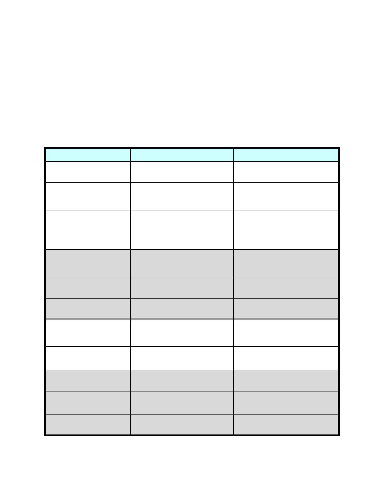
If ordering new service from your telephone company, provide these codes upon request:
Facility Interface Code: 02LS2 Service Order Code: 9.0Y USOC code: RJ-11C
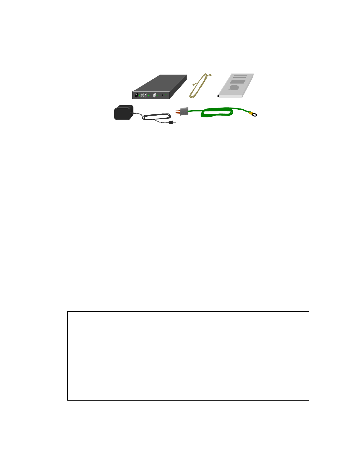
A plug and jack used to connect this equipment to the premises wiring and telephone network must
comply with the applicable FCC Part 68 rules and requirements adopted by the ACTA. A compliant
telephone cord and modular plug is provided with this product. It is designed to be connected to a
compatible modular RJ-11C jack that is also compliant. See installation instructions (Page 13) for
details.
Ringer Equivalence – The TIF-102’s Ringer Equivalence Number (REN) is 0.7. The REN is used to
determine the number of devices that may be connected to a telephone line. Excessive RENs on a
telephone line may result in the devices not ringing in response to an incoming call. In most but not
all areas, the sum of RENs should not exceed five (5.0). To be certain of the number of devices that
may be connected to a line, as determined by the total RENs, contact the local telephone company.
The Ringer Equivalence Number also appears (without its decimal point) in the product identifier –
US:8T5BR07BTIF102.
If your TIF-102 should cause harm to the telephone network, the telephone company will notify you
in advance that temporary discontinuance of service may be required. But if advance notice is not
practical, the telephone company will notify you as soon as possible. Also, you will be advised of
your right to file a complaint with the FCC if you believe it is necessary.
The telephone company may make changes in its facilities, equipment, operations or procedures that
could affect the operation of the equipment. If this happens, the telephone company will provide
advance notice so you can make necessary modifications to maintain uninterrupted service.
In case of trouble with your TIF-102, first follow the troubleshooting steps given in page 17 of this
manual. For repair or warranty information, see Page 21 in this manual, call Applicad Inc at (732)
751-2555, or visit www.aci-applicad.com. If the TIF-102 is causing harm to the telephone network,
the telephone company may request that you disconnect it until the problem is resolved.
This unit contains no user-serviceable parts; please refer any repairs to Applicad (see page 21).
Connection to party line service is subject to state tariffs. Contact the state public utility commission,
public service commission or corporation commission for information.
If your building has specially wired alarm equipment connected to the telephone line, ensure the
installation of your Telephone Interface does not disable your alarm equipment. If you have
questions about what would disable alarm equipment, consult your telephone company or a qualified
installer.

6
Quic Start Guide
– Rear Panel Hoo up
The best way to get familiar with your Telephone Interface is to put it to use. This Quick Start Guide ta es you
through the simple connections, and then shows how to operate its features. If desired, you can s ip ahead to the
Installation Guide (page 12), then turn to Page 7 for operating instructions. To set up your T F-102 for this run-
through, you’ll need a standard des telephone, a live phone jac , two telephone cords, some AC outlets, and a line-
level audio source (CD or MP3 player, etc.). A screwdriver is the only tool needed.
Now you’re ready to try out your Telephone nterface (next page)
Step
5
Plug the cable from the
included AC adapter here.
Plug the other end into a
free AC outlet.
Step 3
Plug the cord from your telephone
into the MONITOR PHONE jac .
Step 2
Connect your audio source to the
LINE IN jac with a RCA cable.
Step 1
Attach the
supplied
green cord to the
GND
terminal. Plug the other end into a grounded AC outlet.
Step 4
Plug your telephone line into
the PHONE LINE jac .
US
:8T5BR07BTIF102 Complies w/ FCC Part 15, Class B
GND 16VAC
PW
R
MONITOR
PHONE
PHONE
LINE
LINE
OUT
COMPRESS
OUT
AUX 1
IN
AUX 2
IN
LINE
IN
RELAY

7
Quic Start Guide
– Basic Operation
Power Up – When the T F-102’s adapter is connected and plugged in, it “wa es up”
switched ON. This way, you can plug the adapter into a power strip along with the
rest of your sound equipment, so that everything powers up together. Press the
blac button to manually switch the unit OFF and ON. The
POWER
LED glows green
when the unit is ready to operate.
12 Hour Option – Normally your TIF-102 “times out” and releases your phone line after
three hours’ continuous connection. Unusually long meetings may require more time. To
select a 12 hour time limit, perform these steps:
•If the unit is already ON, press the POWER button to switch it OFF.
•Press and hold the CONNECT button, press POWER, then release both buttons.
•The CONNECT light blin s several times to confirm the 12 hour selection.
•The CONNECT button also connected the phone line, so press CONNECT again to
disconnect it. The 12 hour setting lasts until the unit is powered down.
Answering a call – Have an assistant call from a “remote phone” (on another line).
You can try this yourself with a cell phone. The
CONNECT
LED lights red to indicate an
incoming call. Simply pic up your telephone’s receiver to answer.
Next, you’ll connect the caller to your audio source. Please start the source playing,
and then continue:
Connecting the caller – Press the
CONNECT
button. This connects the phone line to
the audio from your source. The
CONNECT
LED lights green, and you’ll hear your
source playing through both your phone and the remote phone.
Cradle your phone, and your party remains connected to the program.
Line Release – Hang up the remote phone. After a few seconds, the
CONNECT
light
goes out. The line is now available for another call.
LEVEL
POWER
CONNECT RING
TIF102
COMMENT
Press to connect
your call.
RED – Ringing
GREEN -Connected

8
Quic Start Guide
– Serving your Remote Participant(s)
Using A Teleconferencing Service – Dial out to the service on your phone. Follow the
service’s instructions to establish the conference. Then press
CONNECT
to begin
sending your program there. You may now cradle your phone. After the program
ends: Pic up your phone if necessary, press
CONNECT
again to disconnect the T F-102,
and follow the conference service’s instructions (if any) to end the conference.
If you forget to disconnect your T F-102, it will disconnect automatically after three
hours. This feature limits unnecessary conference charges. Removing power also
ma es the T F-102 disconnect from the phone line.
Serving A Single Caller – You can also have your Phone nterface bring your program
directly to one party. Two-way operation wor s best this way. Have them call your
number, answer your phone and then press CONNECT to begin transmitting the
program.
Conversing with your caller – To chec on your caller, just pic up your phone. To silence
the program, press the CONNECT button. To resume the program, press it again before
cradling your phone.
To keep your party on the line – Keep them connected to the program and/or have them on
your phone. The CONNECT function and your phone act li e “extensions” on your line -- as
long as one is active, the call stays alive.
Disconnecting your call – After you say “Goodbye” to a caller who’s not connected to the
program, simply cradle your phone.
POWER
LEVEL
CONNECT RING
TIF102
COMMENT

9
Quic Start Guide
– Two-Way Operation
To try a two-way conversation with your Telephone Interface, ma e the additional connection to your sound
system shown below:
US:8T5BR07BTIF102 Complies w/ FCC Part 15, Class B
GND 16VAC
PW
R
MONITOR
PHONE
PHONE
LINE
LINE
OUT
COMPRESS
OUT
AUX
LINE
IN
RELAY
Connect the LINE OUT jac to an available line
-
level input on your sound system’s mixer.

10
Quic Start Guide
– Two-way Operation
With the L NE OUT jack wired to your sound system, you can try having a
conversation with a remote caller:
Preparation – Have a mic from your sound system handy, and turn up that channel
just enough so you can hear yourself when you spea into it. Find the mixer input to
which you connected the T F-102’s LINE OUT, and set its control to a low level. Have
an assistant call into your line, and press
CONNECT
to connect this caller as you did
before. The
CONNECT
LED lights green
Comment Request – Have your assistant press the “#” button on their phone’s
eypad. Your Telephone Interface’s
COMMENT
LED blin s red in response. This is how
your remote caller signals that they have something to say.
Enable a Comment – Press the
COMMENT
button once. The
CONNECT
LED now blin s
green. Your system is now in two-way mode, and you can now have a conversation
with your assistant. Slowly turn up the appropriate channels on your sound system’s
mixer (your mic input, and your line input from the Telephone Interface) until both of
you can hear each other. The
LEVEL
LED shows the sound direction – green from the
sound system, red from the remote phone. Any “feedbac ” you hear during this test
won’t happen normally, when your remote caller is outside your auditorium.
Receive Only mode – Press the
COMMENT
button again. The
COMMENT
LED now lights
steady green. You can hear your assistant as they spea into their phone, but they
cannot hear you. The
LEVEL
LED lights red to indicate receive mode. This mode is
useful for receiving a complete program from another location. Press the
COMMENT
button twice to go directly from comment mode to normal transmit mode.
LEVEL
POWER
CONNECT RING
TIF102
COMMENT
OFF –Transmit
Blinking –Two-Way
ON –Receive Only
Blinking Red –
Comment Requested
Press to cycle
through the modes
described below.

11
Directions for Those Calling In
Follow this simple advice for best results when participating via telephone:
•Extensions – Choose which telephone you’ll use and hang up all other
extensions. Additional phones may result in wea or distorted sound.
•Speakerphone – A quality spea erphone ma es
listening easier. Adjust volume so you can hear well, yet
clearly. Keep things quiet on your end – excessive noise
may interrupt your listening. To prevent this, use your
spea erphone’s “mute” button (if available).
Telephone Number & PIN (if used :
•Getting Connected – Dial the provided number and spea with the sound
system operator. They will connect you to the meeting. If your Hall uses a
conference service, dial that number and follow the system prompts.
•Making a Comment – To request a comment, press and
hold the # button on your phone for 1-2 seconds, then release it
(li e raising your hand at a meeting). When you’re as ed for
your comment, spea clearly into the mouthpiece.
•Emergency Call – If someone at your location needs to
ma e a phone call, hang up all your phones and wait five
seconds. Your line should now be free.
•Cell Phone – Listening by cellular phone (especially with “free” minutes) is a
convenient option. Due to noise and echo, however, we don’t
recommend two-way participation via cell phone. If your call
drops, wait about 10 seconds and then reconnect as before.
Remember that the battery in many cell phones (and cordless
phones as well) may not last through the entire program.
Press the
#
button to
request your comment.

12
Installation Guide
– Rear Panel Diagram
`
Phone
Jacks
Connect the PHONE LINE jac to your
telephone line, and the MONITOR
PHONE jac to your nearby telephone.
These jac s are interchangeable.
Power
Jack
Plug in the
AC adapter
(included).
G
ND
Terminal
Provides telephone line surge
protection. Use the included
green cord to connect to a
grounded AC outlet.
This jac provides a level-
compressed version of your
program. Feed a FM transmitter or
recorder from this output. Don’t
connect this output to your mixer or
amplifier (feedback would result).
Compress Output
Line Output
Connect this output to an
available line-level input on
your mixer. Remote sound
appears at this output.
Receives program pic up
from your sound system.
Connect to an unbalanced,
line level feed from your
mixer. Do not connect to a
speaker or 70V line output!
Line Input
US:8T5BR07BTIF102 Complies w/ FCC Part 15, Class B
GND
16VAC
PWR
MONITOR
PHONE
PHONE
LINE
LINE
OUT
COMPRESS
OUT
AUX 1
IN
AUX 2
IN
LINE
IN
RELAY
A line-level source you
connect here passes
through to the LINE
OUTPUT. This can save a
channel on your mixer.
Aux
Inputs
Relay Output
These contacts close when
your remote participant
requests a comment. Max
power handling 28V, 0.5A.

13
Installation Guide
– Telephone Jac
Your Telephone Interface connects to one standard phone line. This line can be
shared with phones, however we recommend you eep one of your building’s lines
free for emergency calls. Don’t connect that line to your Telephone Interface. If your
line already has a RJ-11 phone jac , simply plug in your Telephone Interface using the
supplied phone cord. If you need to install a jac , find one at a hardware store or
home center. They’re not difficult to install.
Caution: To reduce the ris of electric shoc , either unplug the affected phone
line at the building’s networ interface (if equipped), or leave a telephone on this
line “off hoo ” while wiring the jac .
If your wiring uses two-pair cables, its four colors should be red, green, yellow, and
blac . Wire your jac as shown below. If your cable has only one pair, connect its
wires (regardless of color) to the red and green terminals of the jac :
Tip – After wiring your phone jac , plug in a telephone and chec for dial tone. Then use
that phone to call a nearby cell phone -- its Caller ID display identifies your line’s telephone
number. Label your jac with its number as shown.
If with a four-wire cable you find that your jac is dead or on the wrong line, try
interchanging the green / red pair of wires with the blac / yellow pair (in other words, swap
green with blac , and separately swap red with yellow).
Mounting –Place your Telephone Interface where the operator can access it, as well
as away from heat-generating gear such as power amplifiers. For 19” rac mounting,
use our T F-102RMK rac -mount it (purchased separately). Please save the original
front panel and hardware when rac -mounting, so you can revert if needed.
Telephone
cable
Pair 1
832
-
1234
832
-
1234
GRN
RED
RED
GRN
YEL
Pair 2
BLK

14
Installation Guide
– Ma ing Rear Panel Connections
Power – Locate the included AC Adapter. Plug its cord into the Telephone Interface’s
POWER
jac . Plug the adapter into a 120 VAC outlet or power strip.
Ground – Your Telephone Interface includes phone line surge protection. Any
effective surge protection must provide an alternative path for surge currents. You
provide this path by connecting the included green cord between the
GROUND
terminal on your Telephone Interface and a grounded AC outlet. Use either a nearby
wall outlet or an outlet on the power strip feeding your sound gear.
Telephone Line – Connect your line to the
PHONE LINE
jac . If the line includes DSL
Internet service, install a DSL filter ahead of the Telephone Interface.
Monitor Phone – Connect any standard telephone set to the
MONITOR PHONE
jac
using a phone cord. You’ll use this phone to dial out and/or answer calls.
Line In – Your callers hear the audio you provide at the
LINE IN
jac . Connect a feed of
your program, usually available as an “Auxiliary Output” at your sound system’s mic
mixer. If your sound system has an integrated amplifier or powered mixer, examine
its rear panel for a suitable output. If there’s an RCA jac labeled “Aux Output”, “To
Tape Recorder”, etc., this should wor fine. If not, your amplifier may have an “EQ or
Effects Loop” – a pair of jac s possibly labeled “Mixer Out” and “Power Amp In”.
You’ll find these jac s either jumpered together or wired to your equalizer if
equipped. Insert a Y-adapter here to tap your program feed for the Telephone
Interface. If you can’t find a suitable output, please call us for help. Don’t use a
speaker or 70 volt line feed – this would damage your Telephone nterface.
Line Out – Connect to a line-level input on your mixer. This jac outputs the voice of
callers ma ing comments, as well as anything you optionally connect to the
AUX IN
1
and
AUX IN
2
jac s.
Compress Out (Optional) – This jac provides a compressed
version of your program. If you have a FM transmitter for use with
headphones, connect its input here. The
COMPRESS
output’s
consistent level is easier on your listeners than the house feed. In
addition, its built-in 10mS digital delay synchronizes headphone
sound with that arriving from your spea ers, improving clarity.
Caution – Because this output is the compressed program feed from your mixer (supplied to
the LINE IN jac ), never run it bac into your mixer! Feedbac would result.

15
Mic gated ON
Installation Guide –
Wiring Relay Contacts
The Request
RELAY
contacts allow your Telephone Interface to operate a remote
signaling device whenever a caller ma es a request. The
RELAY
contacts clic on and
off (li e a turn signal) for ten seconds when the T F-102 gets a comment request.
Here’s how to connect this feature:
Wire the relay contacts directly in series with a low voltage power source and a
signaling device, as shown above. The green connector unplugs from the Telephone
Interface should you prefer to wire it separately. Pull straight out to unplug.
For power, use a “bell transformer” or any “wall-wart” power cube rated up to 28
volts AC or DC. You can find power adaptors at electronics or surplus supply stores.
You can operate a lamp or other device with the same voltage rating as the power
source, using up to 0.5 ampere current (or the rating of the power source if less). Be
sure to observe polarity for DC devices. A 12 volt DC LED light bar, such as the Wolo
model LTB10 (JC Whitney #ZX157504X, or at many auto stores) ma es a good visual
signal. This uses approx. 400mA at 12VDC.
Installation Guide
– Using A Gated Microphone Mixer
A gated mixer automatically shuts off unused microphones,
reducing bac ground noise and feedbac . We highly
recommend using one. However, we also suggest leaving
one microphone ON at all times for the benefit of your
telephone listeners. Most gated mixers can accommodate
both these goals by selecting an available setting:
Power
Adapter
12 VDC
—
+
RELAY
+
—

16
•“Force ON” (disable gating of) the microphone channel that’s used the most
(typically the “main” or “chairman’s” mic)
•Set the mixer (if not by default) for “Last mic ON” -- the previously active
channel remains live until sound triggers a new channel
Installation Guide
– Adjusting Gain
The gain is factory set to accept a normal level at the LINE IN jac . Adjust it if needed to
accommodate the level of your sound system. Correctly adjusted, incoming sound reaches the
colored input ranges shown on the graph below. Then the T F-102 maintains its ideal output range
as shown. The LEVEL LED responds to sounds within this range, helping you find a good setting.
Ma e the adjustment at the front panel, using a fine slot screwdriver.
To Adjust – Set up your sound system with its most-used microphone. While someone spea s into
this mic (reading a boo wor s well), adjust your sound system’s volume for good auditorium
listening. Then, watch the LEVEL LED at your Telephone Interface:
•If the LED remains dark, increase the gain by turning the screw cloc wise. The LED should
illuminate green and blin orange with program pea s when your auditorium level is
comfortable. Note: It’s OK for the LEVEL LED to light red continuously when playing music,
etc. at levels higher than normal speech. Adjust gain for normal speech.
•If the LED frequently lights for bac ground noise levels in your auditorium, reduce the gain
by turning the adjustment countercloc wise.
•During two-way operation, the
LEVEL
LED wor s differently. Instead of showing transmit
level, it indicates the two-way direction (green for transmit and red for receive).
LEVEL
TIF102
Input s
ound before Compression
O
u
t
p
u
t
S
o
u
n
d
LEVEL
LED
Ideal
Output
Range
Speech
Input
Range
Gain Adjustment
Music, etc.

17
Reference
– Troubleshooting
If you experience any difficulty with your Telephone Interface, please use the
following suggestions to work the problem and find out what’s wrong:
Power – Is all your equipment powered ON? Someone may have inadvertently
switched OFF a component. Test outlets with a lamp or voltmeter. Should your
Phone Interface appear unresponsive, unplug its AC adapter (at either end), wait five
seconds, and reconnect. If the T F-102’s
POWER
LED doesn’t light even though power
is supplied, or if it blin s ON and OFF -- please see Service and Warranty, Page 21.
Sound – Watch the
LEVEL
LED while your participants spea . If it remains dar , the
Telephone Interface is not finding enough sound at its input.
Continue below to resolve this problem:
•Input –Chec that the T F-102’S LINE input is getting sound from
the AUX output of your sound system’s mixer. Be sure that this
cable is fully inserted at both ends.
•Gain Adjustment – Are callers having difficulty hearing the program? If only one caller is
affected, it could be their telephone or line. Otherwise, adjust the gain according to the
procedure on page 16. Note that if this adjustments is inadvertently set to zero (fully
countercloc wise), no sound will transmit.
•Comment Requests – Keep your auditorium reasonably quiet while waiting for comments.
Too much noise may cause your Telephone Interface to miss comment requests.
•Two-Way Switching – During two-way conversations the
COMMENT
LED blin s green, while
the
LEVEL
LED lights green for transmit and red for receive. Use the
LEVEL
LED indication to
troubleshoot any two-way problems. If it shows audio flowing the wrong way, the party
spea ing at that time is not spea ing loud enough to trigger the automatic switching.
Phone Line – The T F-102 automatically tests your phone wiring. If the
CONNECT
LED
doesn’t remain illuminated upon connecting, li ely your line is either unplugged or
out of order. Test the line with a standard telephone set. If you plug this phone into
the TIF102’s
MONITOR PHONE
jac , your test includes both phone line cords.
Conferencing – To diagnose any difficulties with your conference service, test it using
only regular telephones. Test your T F-102 separately (see pages 6 – 10).
If all your tests point to your Telephone Interface as causing the problem,
please see Service and Warranty, Page 21.
LEVEL
TIF102

18
Reference
– How It Wor s
If you have questions about how sound travels between the input and output
jac s of this equipment, the diagram below may help answer them. The diagram also
shows how your Telephone Interface, though simple on the outside, is sophisticated
inside.
•Isolation – This simply means there’s no direct connection from the phone line
jac s to the unit’s electronics. Isolation maintains the integrity of the
telephone networ and the safety of users. The T F-102 isolates using a high-
fidelity, gapped-core “wet” transformer and solid-state optical couplers.
•Surge Protection – Built-in protection uses PTC thermistors to limit surge
currents, and Sidactors® (solid-state triggered switches) to shunt surges to
ground. You supply a reliable ground point by connecting the supplied green
cord from the
GROUND
terminal to a grounded AC outlet.
PIC micro-
controller
A/D
Limiter
Compress
Out
Line
In
Gnd
Line
Amps
Rear Panel Jacks & Connectors
Telephone Jacks
Gain
Adjust
Aux 1
In
Aux 2
In
Line
Out
urge
Protector
Mixer
D/A
3
.8
KHz
LP filter
Delay
D/A
A/D
D/A
SW
SW
SW
Two-way Voice Activity Detection
# Decode
50 MIPS
AD DSP
Level
LED
ense
Boot
Transmit Audio
Receive Audio Limiter
Loop w &
Isolation
T
-
R Logic
UI
DSP Boot
& Control
Timers
Relay Logic
Relay
Front Panel – Buttons & LEDs
Table of contents
Other ACI-AppliCAD Recording Equipment manuals