ACI-AppliCAD TIF-101 Quick start guide

TIF-101 Telephone Interface
Installation and Use
ACI-AppliCAD, Inc.
CONNECT
LEVEL
POWER
RING
TIF101
Version 1.6
Applies to serial # 098710100026 and higher
www.aci-applicad.com

Table of Contents
Introduction ----------------------------------- 2
•Features & Benefits
•What’s In the Box
•FCC Information
Quick Start Guide --------------------------- 5
•Rear Panel Hookup
•Basic Operation
•Serving Your Listeners
Installation Guide --------------------------- 8
•Rear-Panel Diagram
•Telephone Jacks
•Making Rear Panel Connections
•Using A Gated Microphone Mixer
•Adjusting Gain
Reference ---------------------------------------- 12
•Troubleshooting
•How It Works
•Specifications
•Service and Warranty

2
Introduction
The TIF-101 Telephone Interface extends listening to the sound of your
meeting or event over regular phone lines. Microprocessor control provides
easy operation. The TIF-101 appears as an ordinary telephone set to your phone
line, thus works with all teleconferencing services. Your Telephone Interface can
make a real difference for those who need to hear yet cannot e present. Its
quality construction should provide years of relia le service.
Features and Benefits
TIF-101
Feature
What It Does
User Benefit
One-Button Operation No switches or knobs to leave
in the wrong position.
Easy to use, hard to make
mistakes.
Phone Line Release
Disconnects if the caller hangs
up, the connection drops, or
after 3 or 8 hours elapsed time*
Won’t unnecessarily tie up your
phone line or run up conference
service charges.
Microprocessor Control
System
Continuously performs and
monitors all functions.
Provides smart, simple
operating features.
LED Status Lights Indicate telephone line status
and audio level.
You know that your program’s
going out OK.
Compression Manages your sound level. Provides comfortable listening.
Compress Output
for external FM Transmitter
Outputs a level-compressed
version of your program.
Consistent sound level for your
hearing-impaired attendees.
FCC Approval Entire unit tested to comply
with FCC Rules, Parts 15 & 68.
Approved and registered for use
on the telephone network.
Phone Line Protection Built-in phone surge protection.
Reliable operation and long life.
No external protector needed.
* The TIF-101 disconnects from your phone line after three hours by default. To
extend this time limit to eight hours, hold down the CONNECT button while plugging in
the unit’s AC adapter (at either end). The LED blinks red several times to confirm, and
the eight-hour limit remains programmed until power is interrupted.

3
What’s in the Box?
•TIF-101 Telephone Interface
•AC Power Adapter
•1/8” – Dual RCA Cable
•Telephone Cord
•Green Grounding Cord
•This Manual
Anything missing?
If an item listed a ove appears damaged or missing, please call us at ACI-
AppliCAD instead of your vendor, as we are etter a le to respond to your needs.
Find our phone num er in the ervice and Warranty section of this manual.
Power Requirements
Your Telephone Interface operates on 120 VAC 60 Hz AC power (as supplied
throughout the United States), using the included AC adapter. Please do not
attempt to use another power source.
TIF101
Please read and follow our instructions!
Installation is relatively simple ut differs from other telephone
products you may have used or installed. Please do not assume your
new Telephone Interface hooks up the same way as do others. In
particular, do not connect any speaker line (4-8 ohm or 25/70V) to any
jack on this unit. All audio inputs and outputs are “preamp” level RCA
jacks (see pages 5, 8, 10).

4
FCC Information
FCC Part 68 –
This equipment complies with Part 68 of the FCC rules and the requirements adopted by the
ACTA. Its product identifier 8T5BR03BTIF101 also appears on the unit’s rear panel. If requested, this number
must be provided to the telephone company.
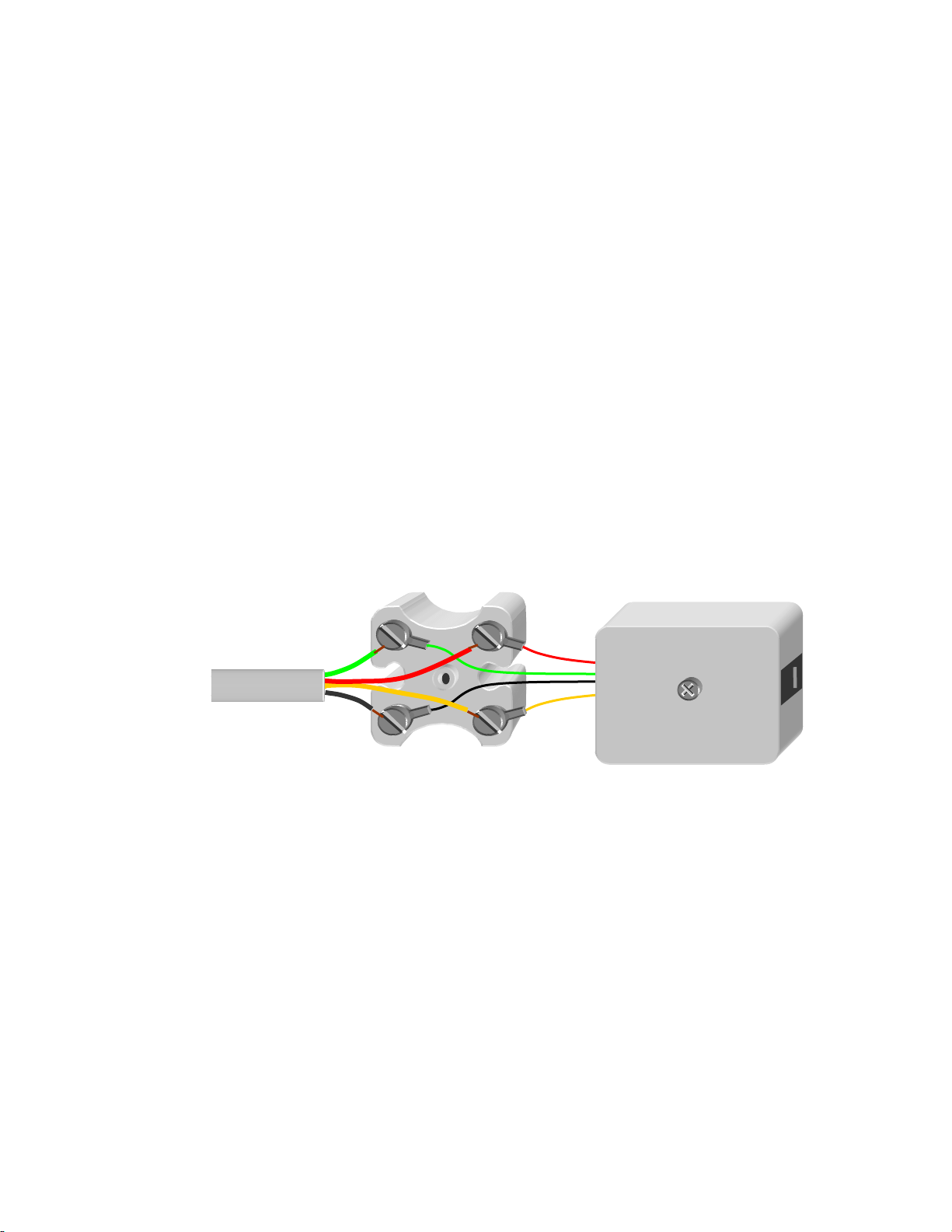
This equipment is designed to be connected to RJ-11C modular telephone jack(s). Plugs, jacks, and cords used to
connect this equipment to the premises wiring and telephone network must comply with the applicable FCC Part 68
rules and requirements adopted by the ACTA. See installation instructions (Page 9) for details.
Ringer Equivalence – The TIF-101’s Ringer Equivalence Number (REN) is 0.3. The REN is used to determine the
number of devices that may be connected to a telephone line. Excessive RENs on a telephone line may result in the
devices not ringing in response to an incoming call. In most but not all areas, the sum of RENs should not exceed
five (5.0). To be certain of the number of devices that may be connected to a line, as determined by the total RENs,
contact the local telephone company.
If trouble is experienced with your Telephone Interface,please do not attempt repairs yourself, but see Page 15 in
this manual. If the TIF-101 is causing harm to the telephone network, the telephone company may request that you
disconnect it until the problem is resolved. Otherwise, the telephone company will notify you in advance that
temporary discontinuance of service may be required. But if advance notice isn't practical, the telephone company
will notify you as soon as possible. Also, you will be advised of your right to file a complaint with the FCC if you
believe it is necessary.
The telephone company may make changes in its facilities, equipment, operations or procedures that could affect the
operation of the equipment. If this happens, the telephone company will provide advance notice so you can make
necessary modifications to maintain uninterrupted service.
Connection to party line service is subject to state tariffs. Contact the state public utility commission, public service
commission or corporation commission for information.
If your building has specially wired alarm equipment connected to the telephone line, ensure the installation of your
Telephone Interface does not disable your alarm equipment. If you have questions about what would disable alarm
equipment, consult your telephone company or a qualified installer.
FCC Part 15 –
The TIF-101 generates, uses, and can radiate radio frequency energy and, if not installed and
used in accordance with the instructions, may cause harmful interference to radio communications. This equipment
has been tested and found to comply with the limits for a Class B digital device as applicable, pursuant to Part 15 of
the FCC Rules. These limits are designed to provide reasonable protection against harmful interference in both
residential and commercial installations. However, there is no guarantee that interference will not occur in a
particular installation. If this equipment does cause harmful interference to radio or television reception, which can
be determined by turning the equipment off and on, the user is encouraged to try to correct the interference by one or
more of the following measures:
•Reorient or relocate the receiving antenna.
•Increase the separation between the equipment and the affected receiver.
•Connect the equipment into an outlet on a circuit different from that to which the receiver is connected.
•Consult the dealer or an experienced radio/TV technician for help.
This device complies with Part 15 of the FCC Rules. Operation is subject to the following two conditions: (1) This
device may not cause harmful interference, and (2) this device must accept any interference received, including
interference that may cause undesired operation.
Because your Telephone Interface complies with the tight FCC Part 15 Class B
guidelines, it is unlikely to interfere with your wireless microphones or other sound
equipment.

5
Quick Start Guide
– Rear Panel Hookup
The est way to get familiar with your Telephone
Interface is to put it to use. This Quick Start Guide
takes you through the simple connections, and then
shows how to operate its features. If desired, you can
skip ahead to the Installation Guide (page 8), then
turn to Page 6 for operating instructions.
To set up your TIF-101 for this run-through, you’ll
need a standard desk telephone, a live phone jack,
two telephone cords, some AC outlets, and a line-
level audio source (CD player, etc.).
A screwdriver is the only tool needed.
F C C – 6 8 R e g. #: 8 T 5 B R 03BTIF101
C o m p l i e s w / FCC P a r t 1 5, Cla s s B
GND
16VAC
PW
R
MONITOR
PHONE
PHONE
LINE 1
Step
6
.
Plug the ca le from the
included AC adapter here.
Plug the other end into a
free AC outlet.
Step
4
.
Plug the cord from your telephone
into the M NIT R PH NE jack.
Step
5
.
Plug your telephone line into
the PH NE LINE 1 jack.
Plug the white LINE IN plug into
your audio source output.
Don’t connect a speaker line or
70V line to this input.
LINE
IN / OUT
Step
2
.
Plug the supplied ca le into this
jack. This splits out the unit’s
LINE
IN
and
C MPRESS UT
plugs.
Step
3
.
Step 1.
Attach the included green cord to the
GND
terminal. Plug the other end into a grounded AC outlet.
COMP ESS
OUT
LINE IN
Remove this sleeve only
if using the Compress OUT
plug (See page 10).

6
Quick Start Guide
– Basic Operation
Now you’re ready to try out your Telephone Interface:
Power Up – The TIF-101 is powered whenever its adapter is plugged in. The
P WER
LED glows green to show that the unit is ready to operate. Many users
prefer to plug the TIF-101’s adapter into an outlet strip along with the rest of
their sound equipment. This way, everything gets powered at once.
Answering a call – Have an assistant call from a “remote phone” (on another
line). You can try this yourself with a cell phone. The
C NNECT
LED lights red to
indicate an incoming call. Simply pick up your telephone’s receiver to answer.
Next, you’ll connect the caller to your audio source. Please start the source
playing, and then continue:
Connecting the caller – Press the
C NNECT
utton. This connects the phone
line to the audio from your source. The
C NNECT
LED lights green, and you’ll
hear your source playing through oth your phone and the remote phone.
Cradle your phone, and your party remains connected to the program.
Line Release – Hang up the remote phone. After a few seconds, the
C NNECT
light goes out. The line is now availa le for another call.
CONNECT
RING
P
O
WER
LEVEL
TIF101
Press to connect
your call.
RED – Ringing
GREEN -Connected

7
Quick Start Guide
– Serving your Listeners
Using A Teleconferencing Service – For est results, use your service’s “Listen
Only” function (if availa le). Dial out to the service on your phone. Follow the
service’s instructions to esta lish the conference. Then press
C NNECT
to egin
sending your program there. You may now hang up your phone. After the
program ends: Pick up your phone if necessary, press
C NNECT
again to
disconnect the TIF-101, and follow the conference service’s instructions (if any)
to end the conference.
If you forget to disconnect your TIF-101, it will disconnect automatically after
three hours (to increase this time to eight hours, see Page 2). This feature
limits unnecessary conference charges. Removing power also makes the TIF-
101 disconnect from the phone line.
Serving A Single Caller – You can also have your TIF-101 send your program
directly to one party. Have them call your num er, answer your phone and
then press CONNECT to egin transmitting the program.
Conversing with your caller – To check on your caller, just pick up your phone. To
silence the program, press the C NNECT utton. To resume the program, press it
again before cradling your phone.
To keep your party on the line – Keep them connected to the program and/or have
them on your phone. The C NNECT function and your phone act like “extensions”
on your line -- as long as one is active, the call stays alive.
Disconnecting your call – After you say “Good ye” to a caller who’s not connected to
the program, simply cradle your phone.
CONNECT
RING
P
O
WER
LEVEL
TIF101

8
Installation Guide
– Rear Panel Diagram
`
Phone
Jacks
Connect the PH NE LINE1 jack to your
telephone line, and the M NIT R
PH NE jack to your near y telephone.
Power
Jack
Plug in the
AC adapter
(included).
G
ND
Terminal
Provides telephone line surge
protection. Use the included
green cord to connect to a
grounded AC outlet.
This plug provides a level-compressed version of
your program. Feed a FM transmitter or
recorder from this output. Don’t connect this
output to your mixer or amplifier (feedback
would result). To use this output, remove its
insulating sleeve and use a RCA extension ca le
(not included) to route the signal where needed.
Compress utput
1/8”
–
RCA “Y” Cable (Supplied)
Plug this ca le, included with
your TIF-101, into the
LINE IN /
UT
jack to access these audio
connections.
Receives program pickup from
your sound system. Connect to
an un alanced, line level feed
from your mixer. Do not connect
to a speaker or 70V line output!
Line Input
FCC – 68 Reg. #: 8T5BR03BTIF101
Complies w/ FCC Part 15, Class B
GND
16VAC
PWR
MONITOR
PHONE
PHONE
LINE 1
LINE
IN / OUT

9
Installation Guide
– Telephone Jacks
Your Telephone Interface connects to one standard phone line. This line can e
shared with phones, however we recommend you keep one of your uilding’s lines
free for emergency calls. Don’t connect that line to your Telephone Interface. If
your line already has a RJ-11 phone jack, connect it to your Telephone Interface
using the supplied phone cord. If you need to install a jack, find one at a hardware
store or home center. They’re not difficult to install.
Caution: To reduce the risk of electric shock, either unplug the affected
phone line at the uilding’s network interface (if equipped), or leave a telephone
on this line “off hook” while wiring the jack.
If your wiring uses two-pair ca les, its four colors should e red, green, yellow,
and lack. Wire your jack as shown elow. If your ca le has only one pair, connect
its wires (regardless of color) to the red and green terminals of the jack:
Tip – After wiring your phone jack, plug in a telephone and check for dial tone. Then use
that phone to call a near y cell phone -- its Caller ID display identifies your line’s telephone
num er. La el your jack with its num er as shown.
If with a four-wire ca le you find that your jack is dead or on the wrong line, try
interchanging the green / red pair of wires with the lack / yellow pair (in other words, swap
green with lack, and separately swap red with yellow).
Mounting –Place your Telephone Interface where the operator can reach it, as well
as away from heat-generating gear such as power amplifiers. For rack mounting,
use our TIF-101RMK rack-mount kit (purchased separately).
Telephone
cable
Pair 1
832
-
1234
832
-
1234
GRN
RED
RED
GRN
YEL
Pair 2
BLK

10
Installation Guide
– Making Rear Panel Connections
Power – Locate the included AC Adapter. Plug its cord into the Telephone
Interface’s
P WER
jack. Plug the adapter into a 120 VAC outlet or power strip.
Ground – Your Telephone Interface includes phone line surge protection. Any
effective surge protection must provide an alternative path for surge currents. You
provide this path y connecting the included green cord etween the
GR UND
terminal on your Telephone Interface and a grounded AC outlet. Use either a
near y wall outlet or an outlet on the power strip feeding your sound gear.
Telephone Line – Connect your line to the
PH NE LINE 1
jack. If the line includes DSL
Internet service, install a DSL filter ahead of the Telephone Interface.
Monitor Phone – Connect any standard telephone set to the
M NIT R PH NE
jack
using a phone cord. You’ll use this phone to dial out and/or answer calls.
Line In – Your callers hear the audio you provide at the white
LINE IN
plug. Connect a
feed of your program to this input, usually availa le as an “Auxiliary Output” at your
sound system’s microphone mixer. If your sound system has an “integrated
amplifier” or a “powered mixer”, examine its rear panel for a suita le output. If
there’s an RCA jack la eled “Auxiliary Output”, “To Tape Recorder”, etc., this should
work fine. If not, your amplifier may have an “EQ or Effects Loop” – a pair of jacks
possi ly la eled “Mixer Out” and “Power Amp In”. You’ll find these jacks either
jumpered together or wired to your equalizer if equipped. Insert a Y-adapter into
this loop to tap your program feed for the Telephone Interface. If you can’t find a
suita le output, please call us for help. Don’t use a speaker or 70 volt line feed.
Compress ut ( ptional) – The red plug provides a compressed
version of your program. If your sound system includes a low-
power FM transmitter for hearing-impaired attendees, connect a
RCA extension ca le (not included) to this red plug, then connect
the extension’s other end into your transmitter’s audio input.
The
C MPRESS
output’s consistent level provides etter results
than would a direct feed from your mixer.
Caution – Because this output is the compressed program feed from your mixer (supplied
to the LINE IN plug), never run it ack into your mixer! Use this output only for devices
independent from your sound system.

11
Mic gated ON
Installation Guide
– Using A Gated Microphone Mixer
A gated mixer automatically shuts off unused microphones, reducing ackground
noise and feed ack. We highly recommend using one. However, we also suggest
leaving one microphone ON at all times for the enefit of your telephone listeners.
Most gated mixers can accommodate oth these goals. Depending upon the model
of gated mixer you have, try one of these settings:
•“Force N” (disa le gating of) the microphone channel that’s used the most
(typically the “main” or “chairman’s” mic)
•
Set the mixer (if not y default) for “Last mic N” -- the previously used
channel remains live until sound triggers a new channel
Installation Guide
– Adjusting Gain
The gain is factory set to accept a normal level at the LINE IN jack. Adjust it if needed to
accommodate the level of your sound system. Correctly adjusted, incoming sound reaches the
ideal input range shown on the graph elow. Then the TIF-101 maintains its ideal output range as
shown. The LEVEL LED responds to sounds within the ideal range, helping you find the correct
setting. Make the adjustment at the front panel, using a fine slot screwdriver.
To Adjust – Set up your sound system with its most-used microphone. While someone speaks
into this mic (reading a ook works well), adjust your sound system’s volume for good auditorium
listening. Then, watch the LEVEL LED at your Telephone Interface:
•If the LED remains dark, increase the gain y turning the screw clockwise. The LED should
illuminate green and link orange with program peaks when your auditorium level is
comforta le. It’s OK for the LEVEL LED to light continuously red when playing music, etc. at
levels higher than normal speech.
•If the LED lights for ackground noise levels in your auditorium, reduce the gain y turning
the adjustment counterclockwise.
CONNECT
RING
P
O
WER
LEVEL
TIF101
Sound efore Compression
O
u
t
p
u
t
S
o
u
n
d
Level
LED
Ideal
Output
Range
Ideal
Input
Range
Gain Adjustment

12
Reference
– Trou leshooting
If you experience any difficulty with your Telephone Interface, please use the
following suggestions to work the pro lem and find out what’s wrong:
Power – Is all your equipment powered ON? Someone may have inadvertently
switched OFF a component. Test outlets with a lamp or voltmeter. If the TIF-101’s
P WER
LED doesn’t light even though you’ve confirmed that power is availa le,
please see ervice and Warranty, Page 15.
Sound – Watch the
LEVEL
LED while your participants
speak. If it remains dark, the Telephone Interface is not
finding enough sound at its input. Continue elow to
resolve this pro lem:
•Input – The white plug from the included “Y” ca le is the input to your TIF-101. Check that
the input is connected to the AUX output of your sound system’s mixer. Be sure that this
ca le is fully inserted at oth the source and the TIF-101.
•Gain Adjustment – Are callers having difficulty hearing the program? If only one caller is
affected, it could e their telephone or line. Otherwise, adjust the gain according to the
procedure on page 11. Note that if this adjustments is inadvertently set to zero (fully
counterclockwise), no sound will transmit.
Phone Line – The TIF-101 automatically tests your phone line for continuity. If the
C NNECT
LED doesn’t remain illuminated when you attempt to connect, your line is
either not plugged in or is out of order. Try using a standard telephone set (such as
your Monitor Phone) with your line as a test. If the line tests good ut your TIF-101
doesn’t recognize it, try another phone cord.
Conferencing – To help discern any difficulties with your conference service, test
your TIF-101 separately, as descri ed on Pages 5-6 of this manual. Also try the
conferencing service using only regular telephones.
If all your tests point to your Telephone Interface as causing the pro lem,
please see ervice and Warranty, Page 15.
CONNECT LEVEL
POWER
RING
TIF101

13
Reference
– How It Works
If you have questions a out how sound travels etween the input and output jacks of this
equipment, the diagram elow may help answer them. The diagram also shows how your
Telephone Interface, though simple on the outside, is sophisticated inside.
•Isolation – This simply means there’s no direct connection from the phone line jacks to the unit’s electronics.
Isolation maintains the integrity of the telephone network and the safety of users. The TIF-101 isolates using
a transformer and solid-state optical couplers.
•Surge Protection – Built-in protection uses PTC thermistors to limit surge currents, and Sidactors® (solid-state
triggered switches) to shunt surges to ground. You supply a relia le ground point y connecting the supplied
green cord from the GROUND terminal to a grounded AC outlet.
•Line Sensing – A out ten seconds after a call concludes, your phone company momentarily drops the DC
power (“loop current”). This is called CPC (Calling Party Control). The TIF-101 senses this to determine that a
call has ended. Then it disconnects and frees the line. Most telephone exchanges also drop loop current
when they quit sending dial tone after a phone has een left “off hook”. Thus, a needlessly connected line
often disconnects automatically.
Peak
Det.
5
-
Pole
active
filter
Compressor
Analog Input
Digital I/O
Microprocessor
Control System
Compress
O t
Line
In
Gro nd
Line
Amp
Rear Panel Jacks & Connectors
Telephone Jacks
Gain
Adj st
S rge
Protector
Isolation &
Control
Front Panel – Buttons & LEDs

14
Reference
– Specifications
Audio Connections:
LINE input, 1/8” (tip) un alanced
C MPRESS Output, 1/8” (ring) un alanced
With supplied 1/8” to dual RCA adapter:
LINE input White, C MPRESS Output Red
Phone Line Connections:
(2) parallel RJ-11 line jacks:
Phone Line
Monitor Phone
Isolation – Transformer & Optical Couplers
Surge Protection – PTCs and Sidactors
®
Loop Sensing – Nominal 15 mA
Off Hook Impedance – Nominal 600 Ohms
FCC ID # – 8T5BR03BTIF101
Power:
3 Watts from 16VAC wall adapter.
Audio Specs:
C MPRESS Output Level approx. 0dBv
LINE Input Level Max +10dBv (recommended 0dBv)
Total Harmonic Distortion < 0.9%
Output level to telephone lines (-9) dB max. per FCC regulations.
Frequency response : (to phone lines) 200 Hz – 3.2 KHz (-29 dB @ 4 KHz per FCC).
(LINE input to C MPRESS output) 200 Hz – 20 KHz
Sidactor
®
is a registered trademark of Teccor Corporation.

15
Reference
– Service & Warranty
We hope you won’t need the following information, ut please e assured that
should your Telephone Interface malfunction, we’re here to help.
You may call ACI-AppliCAD at (732) 751-2555 during normal usiness hours
(Eastern Time) to get help with installing, using, or trou leshooting your Telephone
Interface. If it appears that your Telephone Interface is defective, we’ll issue a RMA
(Return Material Authorization) num er for expert factory service. Please note that
this product uses surface mount technology extensively. We don’t recommend you
attempt internal repairs yourself, even if you’re comforta le around electronics.
Firmware source code is not availa le to customers.
Your limited warranty is one year from date of purchase. Out of warranty, our
current repair charge is a flat rate of $65 plus shipping (su ject to change). Whether
your Telephone Interface is in or out of warranty, you’ll receive fast, courteous
service. Like the TIF-101 itself, we are devoted to solving pro lems in sound
communication.
Manual and internal firmware Copyright © 2009-2014 ACI-AppliCAD, Inc.
Table of contents
Other ACI-AppliCAD Recording Equipment manuals