ACI Hoist & Crane NECH Series User manual

SmartPhone to view our website.
Before equipment use, please read this operation manual
Serial Number:
Date Purchased:
ELECTRIC CHAIN HOIST (Single Brake)
OPERATION MANUAL
This operation manual is intended as an instruction manual for
trained personnel who oversee installation, maintenance, repair
etc.
ELECTRIC CHAIN HOISTS (Single Brake)
Model NECH
ACI Hoist & Crane | 2721 NE 4th Ave Pompano FL 33064 | 954.367.6116 Scan QR Code with

Electric Chain Hoists (Single Brake)
Model NECH
PAGE: 3
NECH-0214
ACI Hoist & Crane | 2721 NE 4th Ave Pompano Beach, FL 33064| 954.367.6116
Visit WWW.ACIHOIST.COM for the most current information
TABLE OF CONTENTS
1.0 WARRANTY .............................................................................................................................................................. 5
2.0 SAFETY PRECAUTIONS........................................................................................................................................... 6
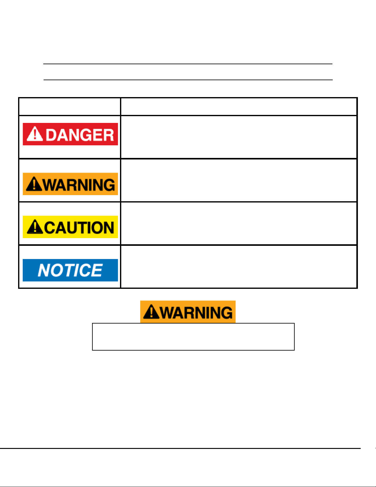
2.1 Safety Alert Symbols .................................................................................................................................................. 6
2.2 Important Information and Warnings ................................................................................................................... 7
2.3 Safe Hoisting and OSHA Compliance ................................................................................................................. 8
2.4 Warning Tags and Labels .................................................................................................................................. 10
2.5 General Safe Operation Requirements.............................................................................................................. 11
3.0 GENERAL DESCRIPTION & FEATURES.................................................................................................................12
3.1 Model Numbering .............................................................................................................................................. 12
3.2 Pendant Control ................................................................................................................................................. 13
4.0 INSTALLATION........................................................................................................................................................15
4.1 Prior to Installing Hoist ....................................................................................................................................... 15
4.2 Installation of Hoist............................................................................................................................................. 16
4.2.1 Installation of Hoist with Trolley .......................................................................................................... 17
4.2.2
Installation of Trolley Hoist on the Beam .................................................................................... 20
4.2.3 Connecting Power Supply to Hoist..................................................................................................... 21
4.2.4 Load Chain ......................................................................................................................................... 21
4.3 Prior To Operation.............................................................................................................................................. 23
4.3.1 Motor Phasing .................................................................................................................................... 23
4.3.1 Trolley Motor Phasing ......................................................................................................................... 24
4.4 Testing Limit Switches ....................................................................................................................................... 24
4.5 Hoist Load Test .................................................................................................................................................. 25
5.0 OPERATION ............................................................................................................................................................26
5.1 General Safety.................................................................................................................................................... 26
5.1.1 General DO’s and DO NOT’S ............................................................................................................. 27
5.2 Safety Rules before Operating the Hoist............................................................................................................ 27
5.3 Safety Rules for Operating the Hoist.................................................................................................................. 28
5.4 Safety Rules for Parking the Load...................................................................................................................... 28
5.5 Safety Rules before Each Shift........................................................................................................................... 29
6.0 INSPECTION ...........................................................................................................................................................30
6.1 Prior to Maintenance or Inspection.................................................................................................................... 30
6.1.1 Inspection Records ............................................................................................................................ 31
6.2 Inspection Classification .................................................................................................................................... 31
6.3 Daily, Frequent & Periodic Inspections.............................................................................................................. 32
6.4 Hook Inspection................................................................................................................................................. 34
6.5 Limit Switch Inspection ...................................................................................................................................... 36
6.6 Load Chain Inspection ....................................................................................................................................... 39
6.7 Hoist Motor Brake Inspection............................................................................................................................. 41

Electric Chain Hoists (Single Brake)
Model NECH
PAGE: 4
NECH-0214
ACI Hoist & Crane | 2721 NE 4th Ave Pompano Beach, FL 33064| 954.367.6116
Visit WWW.ACIHOIST.COM for the most current information
6.8 Trolley Inspection............................................................................................................................................... 42
6.9 Tests................................................................................................................................................................... 44
6.9.1 Operational Test ................................................................................................................................. 44
6.9.2 Load Test............................................................................................................................................ 46
7.0 MAINTENANCE & REPAIR ......................................................................................................................................47
7.1 Lubrication ......................................................................................................................................................... 47
7.1.1 Hoist Gear Housing ............................................................................................................................ 47
7.1.2 Hook Thrust Bearing........................................................................................................................... 48
7.1.3 Chain Lubrication ............................................................................................................................... 48
7.2 Chain Maintenance ............................................................................................................................................ 49
7.3 Chain Replacement............................................................................................................................................ 49
7.4 Hoist Motor Brake Adjustment ........................................................................................................................... 51
7.5 Hoist Motor Brake Disassembly......................................................................................................................... 53
8.0 TROUBLESHOOTING ..............................................................................................................................................55
9.0 WIRING DIAGRAMS ................................................................................................................................................57
10.0 DIMENSIONS & SPECIFICATIONS.......................................................................................................................58
10.1 Table of Specifications..................................................................................................................................... 58
10.2 Hoist Specifications ......................................................................................................................................... 59
10.3 Hoist Dimensions ............................................................................................................................................. 59
11.0 EXPLODED VIEWS & PARTS LISTS ......................................................................................................................62
11.1 Exploded View: Motor & Body Assembly ........................................................................................................ 62
11.2 Parts List: Motor and Body Assembly.............................................................................................................. 63
11.3 Exploded View: Chain Assembly ..................................................................................................................... 65
11.4 Parts List: Chain Assembly .............................................................................................................................. 66
11.5 Exploded View: Hook Assembly ...................................................................................................................... 67
11.6 Parts List: Hook Assembly ............................................................................................................................... 68
11.7 Exploded View: Gear Box Assembly................................................................................................................ 70
11.8 Parts List: Gear Box Assembly......................................................................................................................... 71

Electric Chain Hoists (Single Brake)
Model NECH
PAGE: 5
NECH-0214
ACI Hoist & Crane | 2721 NE 4th Ave Pompano Beach, FL 33064| 954.367.6116
Visit WWW.ACIHOIST.COM for the most current information
Alterations or modifications of equipment and use of non-factory repair
parts can lead to dangerous operation and injury.
To avoid injury:
DO NOT alter or modify equipment.
DO NOT use equipment to lift, support or otherwise transport people.
DO NOT suspend unattended loads over people.
1.0 WARRANTY
Every product is thoroughly inspected and tested before it is shipped from the factory. If any problem develops within
one year, return the product prepaid to the factory. If an inspection reveals that the problem is caused by defective
workmanship or material, repairs will be made without charge and the product will be returned with the shipping prepaid.
Excluded Items
This warranty does not cover:
•Deterioration caused by normal wear, abuse, chemical or abrasive actions, improper maintenance or excessive
heat.
•Problems resulting from repairs, modifications, or alterations made by people other than factory or ACI
representatives.
•If the product has been abused or damaged due to an accident.
•If repair parts or accessories other than ACI equipment are used on the product; they are warranted only to the
extent that they are warranted by the manufacturer of said parts or accessories.
Remarks
EXCEPT AS STATED HERE, ACI MAKES NO OTHER WARRANTIES, EXPRESS OR IMPLIED, INCLUDING WARRANTIES
FOR A PARTICULAR PURPOSE.

Electric Chain Hoists (Single Brake)
Model NECH
PAGE: 6
NECH-0214
ACI Hoist & Crane | 2721 NE 4th Ave Pompano Beach, FL 33064| 954.367.6116
Visit WWW.ACIHOIST.COM for the most current information
2.0
SAFETY PRECAUTIONS
2.1
Safety Alert Symbols
Throughout this manual are steps and procedures that can prevent hazardous situations, the following
symbols are used to identify the degree or level of hazard seriousness.
DANGER, WARNING AND CAUTION NOTICE
Symbol
Description
Danger
Indicates an imminently hazardous situation which, if not avoided,
will result in death or serious injury and property damage.
Warning
Indicates an imminently hazardous situation which, if not avoided,
could result in death or serious injury and property damage.
Caution
Indicates a potentially hazardous situation which, if not avoided, may
result in minor or moderate injury or property damage.
Notice
Notifies people of installation, operation or maintenance information
which is important but not directly hazard related.
This manual contains important information to help you properly install, operate, and maintain the ACI Electric Chain
Hoist for maximum performance and safety purposes. Please study the contents thoroughly before putting the hoist in
operation. Only through proper installation, application of correct operating procedures, and by practicing the
recommended maintenance procedures, can maximum lifting service from the hoist be expected.
The contents of this manual are of necessity, general in nature and may cover features not incorporated on your hoist;
or, you may have ordered features not covered by this manual. Therefore, the user must exercise care in applying
instructions given in this manual. If specific information not in this manual is required, contact the factory. Follow all
instructions and warnings, failure to operate equipment as directed in manual may cause injury.
Failure to read and comply with any of the limitations noted in this
manual can result in serious bodily injury or death, and/or property
damage.

Electric Chain Hoists (Single Brake)
Model NECH
PAGE: 7
NECH-0214
ACI Hoist & Crane | 2721 NE 4th Ave Pompano Beach, FL 33064| 954.367.6116
Visit WWW.ACIHOIST.COM for the most current information
2.2
Important Information and Warnings
•Equipment described in this manual is not designed for and should not be used for lifting, supporting, or
transporting humans.
•To ensure the good working order and reliable operation of the hoist keep strictly to the requirements of the
maintenance and operation given in this manual.
•Keep strictly to the requirements for safe operation in order to prevent dangers from the personnel and damages
to the electric hoist.
•The repairs shall be furnished only with spare parts supplied by the manufacturer.
•Connection of the electric hoist with the power supply shall be furnished only by a qualified electrician.
•Assemblage and putting the electric hoist into use shall only be done by qualified persons, authorized by ACI
Hoist and Crane.
These general instructions deal with the normal installation, operation, and maintenance situations
encountered with the equipment described herein. The instructions should not be interpreted to anticipate
every possible contingency or to anticipate the final system, crane, or configuration that uses this
equipment.
This manual includes instructions and parts information for a variety of hoist types. Therefore, all
instructions and parts information may not apply to anyone type or size of specific hoist. Disregard those
portions of the instructions that do not apply.
Record hoist serial number on the front cover of this manual for identification and future reference to avoid
referring to the wrong manual for information or instructions on installation, operation, inspection,
maintenance, or parts.
It is the responsibility of the owner/user to install, inspect, test, maintain, and operate a hoist in
accordance with ASME B30.16, Safety Standard for Overhead Hoists, OSHA Regulations, and
ANSI/NFPA 70, National Electrical Code. If the hoist is installed as part of a total lifting system, such
as an overhead crane or monorail, it is also the responsibility of the owner/user to comply with the
applicable ASME B30 volume that addresses that type of equipment used in the system.
Further, it is the responsibility of the owner/user to have all personnel that will install, inspect, test,
maintain, and operate a hoist read the contents of the manual and applicable portions of ASME
B30.16, Safety Standard for Overhead Hoists, OSHA Regulations, and ANSIINFPA 70, National
Electrical Code. If the hoist is installed as part of a total lifting system, such as an overhead crane,
the applicable ASME B30 volume that addresses that type of equipment must also be read by all
personnel. Any ANSI Standards referenced in this manual may be obtained from the American
National Standards Institute, 1430 Broadway, New York, NY 10018.
This manual contains information for safe operation of an overhead hoist. Taking precedence over
any specific rule, however, is the most important rule of all "USE COMMON SENSE". Operation of an
overhead hoist involves more than operating the controls. The operator must consider and anticipate
the motions and actions that will occur as a result of operating the controls.

Electric Chain Hoists (Single Brake)
Model NECH
PAGE: 8
NECH-0214
ACI Hoist & Crane | 2721 NE 4th Ave Pompano Beach, FL 33064| 954.367.6116
Visit WWW.ACIHOIST.COM for the most current information
•Modifications to upgrade, rerate, or otherwise alter this equipment shall be authorized only by the original
equipment manufacturer or qualified professional engineer.
Equipment described in this manual may be used in the design and manufacture of cranes or monorails. Additional
equipment or devices may be required for the crane or monorail to comply with applicable crane design and safety
standards. The crane designer, crane manufacturer, or user is responsible to furnish these additional items for
compliance. Refer to ASME B30.17, Safety Standard for Top-Running Single Girder Cranes; ASME B30.2 Safety
Standard for Top-Running Double-Girder Cranes; and ASME B30.11 Safety Standard for Underhung Cranes and
Monorails. If a below-the-hook lifting device or sling is used with a hoist, refer to ASME B30.9, Safety Standard for Slings,
or ASME B30.20, Safety Standard for Below-the-Hook Lifting Devices.
•Hoists and cranes, used to handle hot molten material may require additional equipment or devices. Refer to
ANSI Z241.2, Safety Requirements for Melting and Pouring of Metals in the Metal casting Industry.
•The hoists are not designed to operate in chemically aggressive and explosive environments.
•Failure to read and comply with any of the limitations noted herein can result in serious bodily injury or death,
and/or property damage.
Be advised working in or near exposed energized electrical equipment presents the danger of electric shock.
2.3
Safe Hoisting and OSHA Compliance
The following is a list of the minimum that should be done to keep the hoists and cranes operating properly, safely, and
within OSHA regulations. The following should be done to all hoisting equipment including hand and ratchet hoists.
1. Operator Training: Like forklifts and trucks, operator training is required for every operator of hoisting
equipment (OSHA 1910.179 b.8). Improper lifts are a major cause of lost time accidents. People operating
hoisting equipment must know how to use the equipment safely.
•ACI offers operator-training classes. Classes include; safe rigging, daily equipment inspection, safe
operation, proper use and what can happen with improper use. Classes typically last 1.5 to 2 hours
and can be given in English or Spanish.
2. Preventive Maintenance: A preventative maintenance (PM) program shall be established based on the
manufacturer's recommendations (ANSI B30 .16 2.3 .1a; OSHA 1910.179 Ll).
•ACI offers a PM program based on manufacturers recommendations. ACI has factory-trained
technicians that utilize the proper equipment to do the job correct, fast, and safe. ACI does not
charge for rental of man lifts or forklifts that must be used to operate safely.
3. Qualified Repair Personnel: Adjustments and repairs should be performed by qualified personnel (ANSI
B30.16 16-2.3.3 b).
HAZARDOUS VOLTAGES ARE PRESENT IN THE CONTROL ENCLOSURE, OTHER
ELECTRICAL COMPONENTS AND CONNECTIONS BETWEEN THESE COMPONENTS.
Before performing ANY mechanical or electrical maintenance on the equipment, DISCONNECT
the main switch supplying power to the equipment; and implement LOCKOUT/TAGOUT
procedure. Refer to ANSI Z244.1, Personnel Protection - Lockout/Tagout of Energy Sources.
Do not operate the equipment without control enclosure cover or covers in place.

Electric Chain Hoists (Single Brake)
Model NECH
PAGE: 9
NECH-0214
ACI Hoist & Crane | 2721 NE 4th Ave Pompano Beach, FL 33064| 954.367.6116
Visit WWW.ACIHOIST.COM for the most current information
4. Daily Inspections: Many items must be checked on a daily basis. Written records do not need to be kept for
these inspections (OSHA 1910.179 j 1; ANSI B30.16).
•ACI provides operator-training classes to perform these inspections. These quick inspections are
completed to verify the unit is safe to use prior to daily operation.
5. Frequent Inspections: These inspections are written inspections required on a monthly basis. (OSHA
1910.179 j1; ANSI B30.16).
•ACI can provide these inspections or provide training for your personnel to conduct these
inspections.
6. Periodic Inspections: These are complete inspections and preventative maintenance of the hoists and
cranes. Qualified personnel should determine inspection interval. These should include brake adjustment
and lubrication as well as a complete written inspection of your equipment. (OSHA 1910.179 j 2; ANSI
B30.16).
•Based on use and environment ACI can provide these inspections anywhere from a monthly to an
annual basis. The inspections are designed to maintain the equipment and reduce the long-term
maintenance costs.
7. Records: Dated inspection records shall be kept for inspections and maintenance. (ANSI B30.16 16-2.1.1.2).
Records should be kept where easily available. An external marking is acceptable in lieu of records.
•ACI provides the necessary records. We also keep a copy of all records for your convenience.
8. Load Test: New equipment or equipment that has repairs or alterations to the load handling portion must be
load tested to 125% of rated load. (ANSI B30.16 16-2.2.2). A load test should be performed at a minimum of
every 4 years (CMAA 78 4.7.4). Load test records must be kept for the life of equipment.
•ACI has certified test weights to test your hoists and cranes.
NOTE: There are many special requirements for hoisting systems that should be verified during the design and
inspection of the equipment. It is extremely important for safe operation that the system is designed and maintained by
qualified personnel. ACI would be pleased to provide this service.

Electric Chain Hoists (Single Brake)
Model NECH
PAGE: 10
NECH-0214
ACI Hoist & Crane | 2721 NE 4th Ave Pompano Beach, FL 33064| 954.367.6116
Visit WWW.ACIHOIST.COM for the most current information
ONLY QUALIFIED PERSONNEL
SHALL OPERATE THIS EQUIPMENT
DO NOT:
•
Remove, deface or obscure this label.
•
Operate malfunctioning equipment.
BEFORE OPERATING
DO:
•
REPORT condition for repair by qualified
person.
•
READ Mfr’s. Instruction. Applicable American
national Safety Standards.
•
CHECK ROPE OR CHAIN
Must be seated in grooves, sheaves or
sprockets.
Must not be twisted, kinked or damaged
in any way.
•
CHECK CONTROLS
All limit switches must function properly
Hook travel must be in the same
direction as shown on controls.
•
CLEAR all personnel from service platform
and path of load.
WHILE OPERATING
DO NOT:
•
Lift more than rated load.
•
Lift people or loads over heads of people.
WARN personnel of approaching loads.
•
Make side pulls, Lift all loads vertically.
•
Use limit switches as routine operatingstops.
THESE ARE EMERGENCY DEVICES
ONLY
•
Operate if rope (or chain) slips from groves
(or sprockets). REPLACE in grooves (or
sprockets) before continuing operation.
BEFORE LEAVING OPERATING POSITION
•
DO NOT leave a load suspended and
unattended.
•
ALWAYS disconnect from power supplywhen
equipment is not in use.
ACI
Call: (954)367-6116
WWW.ACIHOIST.COM
2.4
Warning Tags and Labels
The warning tag illustrated below is supplied with each hoist shipped from the factory. If the tag is not attached to your
hoist’s pendant cord, call ACI Hoist & Crane immediately to receive it and install it. Read and obey all warnings attached
to this hoist. Tag is not shown in actual size.

Electric Chain Hoists (Single Brake)
Model NECH
PAGE: 11
NECH-0214
ACI Hoist & Crane | 2721 NE 4th Ave Pompano Beach, FL 33064| 954.367.6116
Visit WWW.ACIHOIST.COM for the most current information
2.5
General Safe Operation Requirements
•Read and observe the instructions and warnings contained in this manual. Read and observe any instructions
and warning tags attached to the hoist.
•Check for any damage to the hoist during shipment. Check carefully to ensure the cable, gearbox, and motor
shell are not damaged. If any damage has occurred, place a claim with the carrier. DO NOT install a damaged
hoist.
•Check that the crane, monorail, or other supporting structure where the hoist will be installed has a load rating
capable to handle loads equal to the rated load capacity of the hoist.
•Check lubricant in gear housing. Oil level should be even with oil level plug in housing. If additional gear housing
lubricant is required, refer to the LUBRICATION section of this manual. Lubricate any exposed gears and pinions
on the trolley.
•Be certain the power supply to the hoist and trolley have the same voltage, frequency, and phase that are
specified on the hoist and trolley nameplate.
Every hoist should be equipped with the following standard accessories:
•One Chain Container
•Control Cable
•One Control Station
Before using the hoist, fill in the information below:
Model Number:
Serial Number:
Purchase Date:
Installation MUST be performed by a qualified person in accordance with ACI Hoist & Crane. Severe injury, death and/or
property damage can result if the hoist is not correctly installed. For service in this area, please contact:
ACI Hoist & Crane
2721 NE 4th Ave
Pompano, FL 33064
Phone: 954-367-6116
Fax: 954-272-0334
Toll Free: 1-866-424-6478
Before installing, removing, inspecting, or performing any maintenance on a hoist, the main switch
shall be de-energized. Lock and tag the main switch in the de-energized position in accordance
with ANSI Z244.1.
Follow other maintenance procedures outlined in the manual and applicable ASME B30 volumes.
Additional WARNINGS are listed in various portions of this manual. Personnel shall read and follow
these WARNINGS. Failure to read and comply with these WARNINGS as well as other instructions
or any limitations noted in this manual and applicable ASME B30 volumes could result in serious
bodily injury or death, and/or property damage.

Electric Chain Hoists (Single Brake)
Model NECH
PAGE: 12
NECH-0214
ACI Hoist & Crane | 2721 NE 4th Ave Pompano Beach, FL 33064| 954.367.6116
Visit WWW.ACIHOIST.COM for the most current information
Trolley Speed
V = Variable
Leave Empty for
Single Speed
Hoist Speed (FPM)
3.0
GENERAL DESCRIPTION & FEATURES
3.1
Model Numbering
NECH H - 010 26 V - 15
Lift (ft.)
10 = 10 ft.
15 = 15 ft.
Etc…
Suspension
H = Hook Mounted
L = Lug Mounted
M = With Motorized Trolley
P = With Standard Push
Trolley
G = With Geared Trolley
Capacity
005 = ¼ Ton
010 = ½ Ton
020 = 1Ton
040 = 2Ton
060 = 3Ton
100 = 5Ton
150 = 7 ½ Ton
200 = 10 Ton
300 = 15 Ton
400 = 20 Ton
600 = 30 Ton
700 = 35 Ton
Type
NECH = Electric Chain

Electric Chain Hoists (Single Brake)
Model NECH
PAGE: 13
NECH-0214
ACI Hoist & Crane | 2721 NE 4th Ave Pompano Beach, FL 33064| 954.367.6116
Visit WWW.ACIHOIST.COM for the most current information
Ensure the motor comes to a complete stop
before reversing the direction.
3.2
Pendant Control
Pendant stations are provided fully assembled. When using a pendant control, depress the up button to raise the hoist or
the down button to lower the hoist as shown in Figure 3.5.1 below. To stop motion, release the buttons.
Figure 3.2.1

Electric Chain Hoists (Single Brake)
Model NECH
PAGE: 15
NECH-0214
ACI Hoist & Crane | 2721 NE 4th Ave Pompano Beach, FL 33064| 954.367.6116
Visit WWW.ACIHOIST.COM for the most current information
4.0
INSTALLATION
ACI electric hoists are lubricated and tested before being shipped from the factory. To place a hoist in service, install the
hoist onto a beam by adjusting the hoist appropriately for the flange width. Then connect it to an electrical service and
perform pre-operation tests, checks and inspections.
4.1
Prior to Installing Hoist
•Read and observe the instructions and warnings contained in this manual. Read and observe any instructions
and warning tags attached to the hoist.
•Locate any vent plugs attached to or included with the hoist and trolley. Remove solid shipping plug or plugs.
•Check that the crane, monorail, or other supporting structure where the hoist will be installed has a load rating
capable to handle loads equal to or greater than the rated load capacity of the hoist.
•If hoist is to be installed on an existing crane, the crane should be run to a location where it will cause the least
interference with other cranes and operations in the area; and all controllers placed in the off position.
•If the hoist is to be installed on an existing crane, and the crane runway remains energized because of other
cranes operating on the same runway; stops or a signal person(s), located full-time at a visual vantage point for
observing the approach of active crane(s), shall be provided to prohibit contact by the active crane(s) with the
idle crane.
•If personnel will be required to work on the runway during installation, a guard or barrier shall be installed
between adjacent runways for the length of the established work area to prevent contact between persons
performing installation and a crane on the adjacent runway.
Prior to installing the hoist check for any damage that may have occurred to the hoist
during shipment.
DO NOT install a damaged hoist.
Only qualified personnel with proper supervision shall install the hoist on the
monorail and perform the final pre-operation inspection.
Before installing, removing, inspecting, or performing any maintenance on a hoist,
the main switch shall be de-energized. Lock and tag the main switch in the de-
energized position in accordance with ANSI Z244.1.
Follow other maintenance procedures outlined in this manual and applicable ASME
B30 volume(s). Additional WARNINGS are listed in various portions of this manual.
Personnel shall read and follow these WARNINGS. Failure to read and comply with
these WARNINGS as well as other instructions or any limitations noted in this manual
and applicable ASME B30 volumes could result in serious bodily injury or death,
and/or property damage.

Electric Chain Hoists (Single Brake)
Model NECH
PAGE: 16
NECH-0214
ACI Hoist & Crane | 2721 NE 4th Ave Pompano Beach, FL 33064| 954.367.6116
Visit WWW.ACIHOIST.COM for the most current information
•If personnel are required to work at elevations in excess of 6 feet above floor or ground level, a fall prevention
policy and procedure shall be developed, documented, and implemented prior to installation.
•Check power supply that will be furnished to the hoist and trolley. It must be the same as shown on the hoist and
trolley serial plate.
•Check load chain for damage. Be sure load chain is properly seated in load sheave and sheave pockets.
•After repair and reassembling of the electric hoist check the phasing and the limit switch adjustment for upper
and lower position of the loading hook.
•While conducting maintenance and repair activities for electric repairs/maintenance, make sure that there is no
load on the hook; the power supply switch is turned off and unauthorized switching on is eliminated.
•Check the loading hook for cracks and deformities as well as the good working order of the fuse for self-release
of the load.
•Check the connection of cable protective conductors to the grounding terminals in the electric board as well as
the transformer and electricity.
•If the hoist has a trolley, check that the crane bridge beam or monorail beam is level, straight, and clean. Check
that trolley stops are installed, or install trolley stops, at the open end or ends of the beam to prevent the trolley
from traveling off the beam. Trolley stops that engage trolley wheels are not recommended. Check that trolley
stops will prevent overhanging parts of the hoist and trolley from interfering with other equipment beyond the
ends of the beam or monorail.
4.2
Installation of Hoist
Prior to mounting the hoist ensure that the suspension and its supporting structure are adequate to support the hoist and
its loads.
•Hook Mounted –Attach the hoist’s top hook to the fixed suspension point. Ensure that the fixed suspension
point rests on the center of the hook’s saddle and that the hook’s latch is engaged.
•Lug Mounted –Fasten securely with lug suspension pins. Check that there are no obstructions to the
operation of the hoist including the path of the chain. Use only the lug mounting hole for suspension of the
hoist.
•Under Running Trolley Hoist Unit - Trolley is mounted on hoist and shipped as one unit. Trolley will operate on
standard S-shapes or W-shapes flanges.
The main switch (disconnect) supplying power to
the crane, monorail, or other piece of equipment
where the hoist is to be installed, shall be de-
energized. Lock and tag the main switch in the de-
energized position in accordance with ANSI Z244.1.

Electric Chain Hoists (Single Brake)
Model NECH
PAGE: 17
NECH-0214
ACI Hoist & Crane | 2721 NE 4th Ave Pompano Beach, FL 33064| 954.367.6116
Visit WWW.ACIHOIST.COM for the most current information
4.2.1 Installation of Hoist with Trolley
If the trolley hoist is mounted on a skid, do not remove it immediately. The skid will hold the trolley hoist unit in an upright
position until assembled on the crane or monorail.
Figure 4.2.1.1
Figure 4.2.1.2
1. Remove cotter pin from trolley shaft dowel pin (Spacer Pin) and slide suspension shaft out of side plate S (refer
to Figures 4.2.1.3 and 4.2.1.4).
Suspension Shaft
Spacer Pin
Side Plate S
Side Plate G

Electric Chain Hoists (Single Brake)
Model NECH
PAGE: 18
NECH-0214
ACI Hoist & Crane | 2721 NE 4th Ave Pompano Beach, FL 33064| 954.367.6116
Visit WWW.ACIHOIST.COM for the most current information
Figure 4.2.1.3 Figure 4.2.1.4
2. Measure the flange width of the beam where the trolley is to be installed.
3. Slide one stack of inner adjusting spacer over the suspension shaft. Total width should be about half of the
flange width of the beam. Then insert suspension shaft into suspender T (refer to Figure 4.2.1.5).
Figure 4.2.1.5
4. Slide same size of inner adjusting spacer stack next to the suspender T and install side plate S to the suspender
shaft (refer to Figure 4.2.1.6).
Suspender
Shaft
Suspender T
Adjusting
Spacer

Electric Chain Hoists (Single Brake)
Model NECH
PAGE: 19
NECH-0214
ACI Hoist & Crane | 2721 NE 4th Ave Pompano Beach, FL 33064| 954.367.6116
Visit WWW.ACIHOIST.COM for the most current information
Figure 4.2.1.6
5. Secure the shaft with spacer pin and cotter pin.
6. Refer to Figure 4.2.1.7 for adjusting the width of the trolley by installing inner and outer adjusting spacers on the
suspension shaft.
Figure 4.2.1.7
7. Make sure both side plates are spread fully outward and measure dimension “A”. Dimension “A” must be 5/32”
(4 mm) greater than “B” (refer to Figure 4.2.1.7).
8. Rearrange spacers, if necessary, to achieve proper spacing. Distribute washers equally so that the hoist will be
centered between trolley side plates and under beam.
9. After obtaining the proper adjustment, secure the shaft with spacer pin and cotter pin.
Even if the unit was ordered for a specific beam size or beam flange width; check trolley wheel s pacing between
wheel flanges.
Adjusting
Spacers

Electric Chain Hoists (Single Brake)
Model NECH
PAGE: 20
NECH-0214
ACI Hoist & Crane | 2721 NE 4th Ave Pompano Beach, FL 33064| 954.367.6116
Visit WWW.ACIHOIST.COM for the most current information
4.2.2
Installation of Trolley Hoist on the Beam
1. Place trolley hoist in correct position relative to bridge beam or monorail, orienting it for proper end approach in
accordance with specification requirements. Be sure that collectors and conductors are properly positioned and
aligned.
2. Place Trolley hoist unit in position on bridge beam or monorail. Check that trolley bumpers, if provided, meet
trolley stops on beam, reposition if necessary.
The simplest ways to mount the trolley hoist on the beam, as long as the crane or building construction permits it, is to
remove the trolley stops on an open end of the beam, run the trolley onto the beam and replace the trolley stops. If this
method is not possible due to crane or building interference, mount the trolley hoist according to the following instructions
(refer to Figure 4.2.2.1).
Figure 4.2.2.1
3. Remove side plate assembly, with the wheels intact, from one side of the trolley only, by removing the spacer pin
from the suspension shaft hole A. Then insert it into hole B. Insert cotter pin in the spacer pin to fix it in place. On
geared and motorized trolleys it is recommended that the side with the plain wheels be removed.
4. Spread side plate G and side plate S apart. Lift the trolley up to the beam; keep both sides of the wheel and
beam at the same level.
5. Support one side plate then push the other side towards the supported side to prevent it from shedding from the
beam. Keep the wheel and the beam at the same level.
6. Remove the spacer pin from hole B and insert it into hole. Secure the spacer pin with the cotter pin.
7. Check that the hoist is centered between trolley side plates and centered under the beam.
8. The load block must hang straight and directly under the hoist. The load chain must be free of kinks, twists or
any other damage.
Trolley hoists are balanced at the factory based upon the condition of the hoist “as ordered” and “as shipped”. Auxiliary
equipment or devices furnished and mounted by others may require additional counterweights to balance the hoist. It is the
responsibility of the party mounting such auxiliary equipment or devices to add additional counterweights as necessary and
required.
If the load chain welding points are not inline you must replace the load
chain before use.
This manual suits for next models
17
Table of contents
Other ACI Hoist & Crane Chain Hoist manuals