ACI Hoist & Crane MH User manual

Mechanics Hoists
Mechanics Hoists PAGE: 1
Model MH MH-0214
2721 NE 4th Ave Pompano FL 33064| (954) 367-6116 Visit WWW.ACIHOIST.COM for the most current information
OPERATION MANUAL
This operation manual is intended as an instruction manual for trained
personnel who are in charge of installation, maintenance, repair etc.
Version # MH-0214
Before equipment use, please read this operation manual
carefully.

Mechanics Hoists PAGE: 2
Model MH MH-0214
2721 NE 4th Ave Pompano FL 33064| (954) 367-6116 Visit WWW.ACIHOIST.COM for the most current information

Mechanics Hoists PAGE: 3
Model MH MH-0214
2721 NE 4th Ave Pompano FL 33064| (954) 367-6116 Visit WWW.ACIHOIST.COM for the most current information
TABLE OF CONTENTS
1.0 WARRANTY .............................................................................................................................................................. 5
2.0 SAFETY PRECAUTIONS........................................................................................................................................... 6
2.1 Safety Alert Symbols...................................................................................................................................... 6
3.0 INSTALLATION......................................................................................................................................................... 7
3.1 Unpacking ..................................................................................................................................................... 7
3.2 Pre-installation Checks .................................................................................................................................. 7
3.3 Power Supply System.................................................................................................................................... 7
3.4 Connection to the Electrical Supply ............................................................................................................... 8
3.5 Mounting the Hoist ........................................................................................................................................ 8
3.6 Hook and Eye Suspension Hoists.................................................................................................................. 8
3.7 Load Chain.................................................................................................................................................... 8
3.8 Load Chain Lubrication.................................................................................................................................. 8
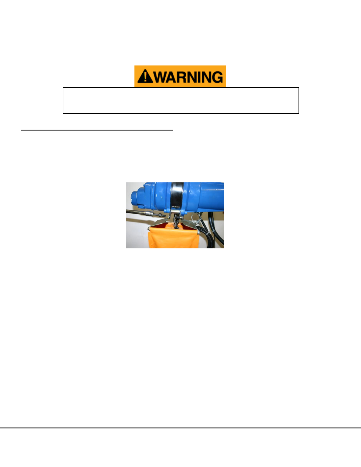
3.9 Chain Container............................................................................................................................................. 9
3.9.1 Installation of Standard Chain Container.......................................................................................... 9
4.0 OPERATION............................................................................................................................................................ 10
4.1 Test and Operational Checks........................................................................................................................10
4.2 Operation Personnel.....................................................................................................................................11
4.3 Product Warnings .........................................................................................................................................11
4.4 Product Cautions..........................................................................................................................................12
5.0 INSPECTION........................................................................................................................................................... 14
5.1 General.........................................................................................................................................................14
5.2 Inspection Classification ...............................................................................................................................14
5.3 Frequent Inspection......................................................................................................................................15
5.4 Periodic Inspection .......................................................................................................................................15
5.5 Occasionally Used Hoist...............................................................................................................................16
5.6 Inspection Reports........................................................................................................................................16
5.7 Inspection Methods and Criteria ...................................................................................................................16
5.8 Chain Inspection...........................................................................................................................................18
6.0 MAINTENANCE AND REPAIR................................................................................................................................ 19
6.1 Cutting the Chain..........................................................................................................................................19
6.2 Lubrication....................................................................................................................................................19
6.3 Replacing Gear Brakes & Oil.........................................................................................................................20
6.4 Testing .........................................................................................................................................................21
7.0 TROUBLESHOOTING............................................................................................................................................. 22
8.0 WIRING DIAGRAM ................................................................................................................................................. 23
9.0 DIMENSIONS & SPECIFICATIONS........................................................................................................................ 24
10.0 EXPLODED VIEWS & PARTS LISTS..................................................................................................................... 26

Mechanics Hoists PAGE: 4
Model MH MH-0214
2721 NE 4th Ave Pompano FL 33064| (954) 367-6116 Visit WWW.ACIHOIST.COM for the most current information
10.1 Repair Parts –Ordering Instructions............................................................................................................26
10.2 Exploded View: MH-005 & MH-010 .............................................................................................................27
10.3 Exploded View: MH-020..............................................................................................................................28
10.4 Parts List: MH-005, MH-010, & MH-020 .......................................................................................................29
10.5 Exploded View: MH Pendant.......................................................................................................................32
10.6 Parts List: MH Pendant ...............................................................................................................................33

Mechanics Hoists PAGE: 5
Model MH MH-0214
2721 NE 4th Ave Pompano FL 33064| (954) 367-6116 Visit WWW.ACIHOIST.COM for the most current information
1.0 WARRANTY
Every product is thoroughly inspected and tested before it is shipped from the factory. If any problem develops within
one year, return the product prepaid to the factory. If an inspection reveals that the problem is caused by defective
workmanship or material, repairs will be made without charge and the product will be returned with the shipping prepaid.
Excluded Items
This warranty does not cover:
Deterioration caused by normal wear, abuse, chemical or abrasive actions, improper maintenance or excessive heat.
Problems resulting from repairs, modifications, or alterations made by people other than factory or ACI
representatives.
If the product has been abused or damaged due to an accident.
If repair parts or accessories other than ACI equipment are used on the product; they are warranted only to the
extent that they are warranted by the manufacturer of said parts or accessories.
Remarks
EXCEPT AS STATED HERE, ACI MAKES NO OTHER WARRANTIES, EXPRESS OR IMPLIED, INCLUDING WARRANTIES
FOR A PARTICULAR PURPOSE.
Alterations or modifications of equipment and use of non-factory repair
parts can lead to dangerous operation and injury.
To avoid injury:
DO NOT alter or modify equipment.
DO NOT use equipment to lift, support or otherwise transport people.
DO NOT suspend unattended loads over people.

Mechanics Hoists PAGE: 6
Model MH MH-0214
2721 NE 4th Ave Pompano FL 33064| (954) 367-6116 Visit WWW.ACIHOIST.COM for the most current information
2.0 SAFETY PRECAUTIONS
2.1 Safety Alert Symbols
Throughout this manual are steps and procedures that can prevent hazardous situations, the following symbols are used
to identify the degree or level of hazard seriousness.
DANGER, WARNING AND CAUTION NOTICE
Symbol
Description
Danger
Indicates an imminently hazardous situation which, if not
avoided, will result in death or serious injury and
property damage.
Warning
Indicates an imminently hazardous situation which, if not
avoided, could result in death or serious injury and
property damage.
Caution
Indicates a potentially hazardous situation which, if not
avoided, may result in minor or moderate injury or
property damage.
Notice
Notifies people of installation, operation or maintenance
information which is important but not directly hazard
related.
Failure to read and comply with any of the limitations noted in this manual can result in serious bodily
injury or death, and/or property damage.

Mechanics Hoists PAGE: 7
Model MH MH-0214
2721 NE 4th Ave Pompano FL 33064| (954) 367-6116 Visit WWW.ACIHOIST.COM for the most current information
3.0 INSTALLATION
3.1 Unpacking
Once package has been opened, carefully inspect the hoist frame, hooks, chain and control station for damage that may
have occurred during shipment. If damage is found please contact your ACI representatives immediately at, toll free
1-866-424-6478.
Make sure to check that the power supply to which the hoist is to be connected matches the information shown on the
identification plate located on the bottom of the hoist.
Before using the hoist, fill in the information below:
Model Number:_________________________
Serial Number: _________________________
Purchase Date: ________________________
3.2 Pre-installation Checks
Check for transit damage.
Check that all fasteners and joints are tight and secure.
Check the capacity of the lifting unit and bottom block.
Check that all external wiring is in good order.
Check that the load chain is in good order.
3.3 Power Supply System
To insure proper operation, to avoid damage to the hoist and electrical system, and to reduce the risk of electrical shock
or fire, the branch circuit supplying power to the hoist must:
Be in accordance with the National Electrical Code (ANSI/NFPA-70) and applicable National, State and Local
codes.
Effectively ground the hoist in accordance with the National Electrical Code and other applicable codes. Proper
grounding provides a path with the least resistance for the electrical current to travel reducing the risk of
electrical shock. The standard power cord is equipped with a three prong plug, used with our 115V-1PH-60HZ
unit. Make sure that the receptacle opening that receives the longest prong is properly grounded.
Have ample capacity to prevent excessive voltage drop during starting and operation. When determining the size
of branch circuit components and conductors, special consideration should be given to the starting current
amps (approximately three times that shown on the hoist identification plate) and the length of the conductors.
As a minimum, the system should be rated for 20 amps and the system should have #14 AWG or larger, wiring.
Operating a unit with obvious external damage may cause load to
drop and could result in personal injury and/or property damage.
To avoid injury: Carefully check unit for external damage prior to
installation.

Mechanics Hoists PAGE: 8
Model MH MH-0214
2721 NE 4th Ave Pompano FL 33064| (954) 367-6116 Visit WWW.ACIHOIST.COM for the most current information
Include slow blow type fuses or inverse trip time circuit breakers to permit the hoist to start and accelerate the
load.
Include a disconnecting means capable of being locked in the ‘open’ position.
3.4 Connection to the Electrical Supply
An adequate supply system is required along the total length of travel (where appropriate). The supply voltage and
frequency, at which the hoist operates, is marked on the motor rating plate. It is imperative to check before connecting
the unit that these figures correspond with those of the supply voltage.
3.5 Mounting the Hoist
Hang the hoist from its intended support. The structure used to support the hoist must have sufficient strength to
withstand several times the load amount. If you are not sure of the weight the structure can hold, consult a registered
engineer and the local building codes.
3.6 Hook and Eye Suspension Hoists
The suspension point should be of a correct size to admit the top hook or eye of the hoist and allow it to rest properly on
the saddle. It must be adequate to support the hoist while it is being operated at its maximum capacity (safe working
load).
3.7 Load Chain
The chain should feed smoothly into and away from the hoist and hook block (¼ ton and 1 ton). If the chain binds, jumps
or is noisy, First clean and lubricate the chain, if trouble persists inspect chain and mating parts for wear, distortion and
other damages.
3.8 Load Chain Lubrication
Always lubricate load chain weekly or more frequently depending on severity of service. Lubricate load chain with a light
coat of Lubriplate Bar and Chain Oil 10-R (Fiske Bros. Refining Co.) or equal lubricant. Be sure the lubricant reaches the
bearing surfaces between the links. Remove the excess oil from the chain.
Used motor oils contain unknown carcinogenic materials. Never use used motor oils as a chain
lubricant. Only use Lubriplate Bar and Chain Oil 10-R or equal lubricant as a lubricant for the
load chain.
Suspending the hoist from an inadequate support could allow the hoist and load to fall
and cause personal injury and/or property damage. Make sure that the structure has
sufficient strength to withstand several times the hoist and its rated load amount. Using
the upper hook, hang the hoist from the support. Make sure the hoist is solidly held in the
uppermost part of the hook arc and the latch is tightly against the hook tip.

Mechanics Hoists PAGE: 9
Model MH MH-0214
2721 NE 4th Ave Pompano FL 33064| (954) 367-6116 Visit WWW.ACIHOIST.COM for the most current information
3.9 Chain Container
For installations where the slack chain hanging from the hoist may be objectionable or hazardous, the use of a chain
container is recommended.
3.9.1 Installation of Standard Chain Container
1. Remove both bolts from the chain container mounting bracket (see Figure 3.9.1.1).
2. Attach the chain container to the bracket.
3. Reinsert the bolts.
Figure 3.9.1.1
Do not attempt to store more chain in the chain container than what is specified for
the hoist or serious damage to hoist may result and hazardous conditions may be
created.

Mechanics Hoists PAGE: 10
Model MH MH-0214
2721 NE 4th Ave Pompano FL 33064| (954) 367-6116 Visit WWW.ACIHOIST.COM for the most current information
4.0 OPERATION
4.1 Test and Operational Checks
On completion of installation, but before the hoist is put into regular service, the following procedure should be carried
out:
Record the hoist’s Code, Lot and Serial Number from the name plate on the hoist.
Check that the hoist is properly installed to either a fixed point or trolley, whichever applies.
If hoist is installed on a trolley, ensure that:
The trolley is properly installed on the beam.
The stops for the trolley are correctly positioned and securely installed on the beam.
Isolate the power supply.
Check that all mechanical and electrical joints and connections are tight and secure.
Check that all nuts, bolts and split pins (cotter pins) are securely fastened.
Confirm proper operation:
Before operating read and become familiar with this manual.
Before operating check to ensure that the hoist and trolley meet the Inspection, Testing and Maintenance
requirements of ANSI/ASME B30.16.
Before operating check that nothing will interfere with the full range of the hoist’s (and trolley’s) operation.
Switch on the power supply.
Run lightly with no load, throughout the full extent of the hoist and check that the operation is smooth at all times.
Check the operation of the hoist brake, run under light load and full load conditions.
Check supply voltage before everyday use. If the voltage varies more than 10% of the
rated value, electrical devices may not function normally.
Confirm the adequacy of the rated capacity for all slings, chains, wire ropes and
all other lifting attachments before use. Inspect all load suspension members for
damage prior to use and replace or repair all damaged parts.

Mechanics Hoists PAGE: 11
Model MH MH-0214
2721 NE 4th Ave Pompano FL 33064| (954) 367-6116 Visit WWW.ACIHOIST.COM for the most current information
4.2 Operation Personnel
For independent operation or maintenance of chain hoist, the owner may only employ persons as following:
Must be at least 18 years of age.
Must be mentally and physically suitable.
Those who have been instructed in the operation and/or maintenance of the chain hoist and have proven their
qualification to the owner in this respect. In addition to theoretical training, instruction also includes sufficient
practical operating experience as well as acquiring the ability to identify defects which are a hazard to safe
operations.
4.3 Product Warnings
DO NOT…
DO NOT operate the hoist until you have read the Operating, Maintenance and parts manual.
DO NOT operate a damaged or malfunctioning hoist.
DO NOT use the hoist to lift, support or transport people.
DO NOT operate the hoist until all personnel are clear of the supported load.
DO NOT lift loads over personnel.
DO NOT remove or obscure the warning labels on the hoist.
DO NOT operate a hoist on which the safety place cards or decals are missing or illegible.
DO NOT operate a hoist which has been modified without the manufacturer’s approval or without certification
that it is in conformity with ANSI/ASME B30 volumes.
DO NOT use hoist with twisted, kinked, damaged or worn load chain.
DO NOT use load chain as a sling or wrap the chain around the load.
DO NOT operate a hoist unless the load slings or other approved single attachments are properly sized and
seated in the hook saddle.
DO NOT lift more than the rated load for the hoist.
DO NOT operate unless load is centered under the hoist properly.
DO NOT apply the load unless load chain is properly seated in the chain sprocket(s).
Verify and correct all chain irregularities prior to operating the hoist.
Warning indicates an imminently hazardous situation which, if not avoided, could result
in death or serious injury, and property damage.

Mechanics Hoists PAGE: 12
Model MH MH-0214
2721 NE 4th Ave Pompano FL 33064| (954) 367-6116 Visit WWW.ACIHOIST.COM for the most current information
DO NOT apply load if bearing prevents equal loading on all load supporting chains.
DO NOT operate hoist when it is restricted from forming a straight line from hook to hook in the direction of
loading.
DO NOT attempt to lengthen the load chain or repair the damaged load chain.
DO NOT apply the load to the tip of the hook or to the hook latch.
DO NOT operate beyond the limits of the load chain travel.
DO NOT leave the load (supported by the hoist) unattended unless specific precautions have been taken.
DO NOT operate a hoist until it has been securely attached to a suitable support.
DO NOT allow the load chain or hook to be used as an electrical or welding ground.
DO NOT allow the load chain or hook to be touched by a live welding electrode.
DO…
DO shut down a hoist that malfunctions or performs unusually and report such malfunction.
DO make sure that the hoists limit switches function properly.
DO warn personnel of an approaching load.
DO take up slack carefully –make sure the load is balanced and the load holding action is secure before
continuing.
DO protect the hoist’s load chain from weld splatter or other damaging contaminants.
4.4 Product Cautions
DO NOT:
DO NOT allow your attention to be diverted from operating the hoist.
DO NOT allow the hoist to be subjected to sharp contact with other hoist, structures or objects through misuse.
DO NOT adjust or repair the hoist unless qualified to perform such adjustments or repairs.
DO NOT use the hoist overload limiting clutch to measure the load.
DO:
DO inspect the hoist regularly, replace damaged or worn parts and keep appropriate records of maintenance.
DO maintain firm footing or be otherwise secured when operating the hoist.
DO check brake function by tensioning the hoist prior to each lift operation.
DO lubricate load chain per hoist manufacturer’s recommendations.
DO use Mechanics Hoist MH recommended parts when repairing the hoist unit.
Caution indicates a potentially hazardous situation which, if not avoided, may result in
minor or moderate injury, or property damage.

Mechanics Hoists PAGE: 13
Model MH MH-0214
2721 NE 4th Ave Pompano FL 33064| (954) 367-6116 Visit WWW.ACIHOIST.COM for the most current information
DO use the hook latches. Latches are to retain slings, chains, etc. under slack conditions only.
DO make sure the hook latches are closed and not supporting any parts of the load.
DO make sure the load is free to move and will clear all obstructions.
DO avoid swinging the load or hook.
DO make sure the hook travel is in the same direction as shown on the controls.

Mechanics Hoists PAGE: 14
Model MH MH-0214
2721 NE 4th Ave Pompano FL 33064| (954) 367-6116 Visit WWW.ACIHOIST.COM for the most current information
5.0 INSPECTION
5.1 General
The inspection procedure is based on ANSI/ASME B30.16. The following definitions are from ANSI/ASME B30.16 and
pertain to the inspection procedure below.
Designated Person: A person assigned or selected as being competent to perform the specific duties to which
he/she is assigned.
Qualified Person: A person who, by possession of a recognized degree or certificate of professional standing, or
who, by extensive knowledge, training and experience has successfully demonstrated the ability to solve or
resolve problems relating to the subject matter at work.
Normal Service: A distributed service which involves operation with randomly distributed loads within the rated
load limit or uniform loads less than 65% of rated load for not more than 25% of the time.\
Heavy Service: A service which involves operation within the rated load limit which exceeds normal service.
Severe Service: A service which involves normal or heavy service with abnormal operating conditions.
5.2 Inspection Classification
The inspection procedure for hoist in regular service is divided into two general classifications based upon the intervals
at which inspection should be performed. The intervals in turn are dependent upon the nature of the critical components
of the hoist and the degree of their exposure to wear, deterioration or malfunction. The two general classifications are
designated as Frequent and Periodic, with respective intervals between inspections as defined below.
FREQUENT INSPECTIONS - Frequent inspections are visual examinations by the operator or other designated personnel
with interval per the following criteria.
Normal Service –Monthly
Heavy Service –Weekly to Monthly
Severe Service –Daily to Weekly
Special or Infrequent Service –As recommended by a qualified person before and after each occurrence.
PERIODIC INSPECTIONS - Periodic inspections are visual inspections by a designated person with interval per the
following criteria.
Normal Service –Yearly
Heavy Service –Semi-Annually
Severe Service –Quarterly
Special or Infrequent Service –As recommended by a qualified person before the first occurrence.
Prior to initial use, all new, altered or modified hoists shall be inspected by a designated
person to ensure compliance with the applicable provisions of this manual.

Mechanics Hoists PAGE: 15
Model MH MH-0214
2721 NE 4th Ave Pompano FL 33064| (954) 367-6116 Visit WWW.ACIHOIST.COM for the most current information
5.3 Frequent Inspection
Inspections should be made on a frequent basis in accordance with Table 6.3.1. Included in these Frequent Inspections
are observations made during operation for any defects or damage that might appear between Periodic Inspections.
Frequent Inspections shall be made by a designated person to ensure that the hoist is maintained in safe working
condition.
Table 6.3.1
FREQUENT INSPECTION
1. Check all functional operating mechanisms for maladjustment and unusual sounds.
2. Check the operation of the limit switch and associated components.
3. Check the hoist braking system for proper operation.
4. Check the hooks in accordance with ANSI/ASME B30.10.
5. Check the hook latch operation.
6. Check the Load Chain for twists, cracks, dents, wear and obstructions.
7. Check the Load Chain reeving.
5.4 Periodic Inspection
Inspections should be made on a Periodic basis in accordance with Table 6.4.1. Evaluation and resolution of the results
of Periodic Inspections shall be made by a designated person to ensure that the hoist is maintained in safe working
condition.
Table 6.4.1
PERIODIC INSPECTION
1. Complete the requirements of Frequent Inspection.
2. Check to ensure there is no evidence of loose bolts, nuts or rivets.
3. Check to ensure there is no evidence of damage or excessive wear of load and
idler sheaves.
4. Check to ensure there is no evidence of damage to hook retaining nuts or collars
and pins, and welds or rivets used to secure the retaining members.
5. Check to ensure the warning label is properly attached to the hoist and legible.
6. Check to ensure the function labels on the pendant control stations are legible.
7. Check to ensure there is no evidence of worn, corroded, cracked or distorted parts
such as load blocks, suspension housing, chain attachments, clevises, yokes,
suspension bolts, shafts, gears, bearings, pins and rollers.
8. Check to ensure there is no evidence of damage to the supporting structure or
trolley, if used.
9. Check to ensure there is no evidence of damage to the end connections of the
load chain.
10. Check to ensure there is no evidence of excessive wear on motor or load brake.
11. Check to ensure there is no electrical apparatus for signs of pitting or any
deterioration of visible controller contacts.
For inspections where load suspension parts of the hoist are disassembled, a load test
per ANSI/ASME B30.16 must be performed on the hoist after it is re-assembled and prior
to its return to service.

Mechanics Hoists PAGE: 16
Model MH MH-0214
2721 NE 4th Ave Pompano FL 33064| (954) 367-6116 Visit WWW.ACIHOIST.COM for the most current information
5.5 Occasionally Used Hoist
Hoists that are infrequently used shall be inspected as follows before placing the hoist in service:
Hoist idle more than one year: Inspect per Periodic Inspection.
Hoist idle more than one month, less than one year: Inspect per Frequent Inspection.
5.6 Inspection Reports
Dated inspection reports and records should be maintained for the hoist Periodic Inspection intervals. These
records should be stored where they are available to personnel involved with the inspection, maintenance or
operation of the hoist.
A long range chain inspection program should be established and should include records of an examination of
the chains that are removed from service to create a relationship between visual observation and actual condition
of the chain.
5.7 Inspection Methods and Criteria
This section covers the inspection of specific items. The list of items in this section is based on those listed in
ANSI/ASME B30.16 for the Frequent and Periodic Inspection. In accordance with ANSI/ASME B30 volumes listed under
the General heading on the previous pages, these inspections are not intended to involve disassembly of the hoist.
Rather, disassembly for further inspection would be required if frequent or periodic inspection results so indicate. Such
disassembly and further inspection should only be performed by a certified or qualified person trained in the disassembly
and re-assembly of the hoist.
Table 5.7.1
Hoist Inspection Methods and Criteria
Item
Method
Criteria
Action
Functional
operating
mechanisms
Visual, Auditory
Mechanisms should be properly
adjusted and should not produce
unusual sounds when operated.
Repair or replace as required
Braking System
Operation
Function
Braking distance with rated capacity
should not exceed approximately
five chain links.
Repair or replace as required
Hooks
(surface condition)
Visual
Should be free of significant rust,
weld splatter, deep nicks or
gouges.
Replace
Hooks
(fretting wear)
Measure
The “F” and “T” dimensions should
not be less than discard value listed
in Dimensions & Specifications
Table 3.1.5.
Replace
Hooks (stretch)
Measure
The “D” dimension should not
exceed the measured value for
discard from Dimensions &
Specifications Table 3.1.5.
Replace
Hooks (bent shank
or neck)
Visual
Shank and neck portions of hook
should be free of deformations.
Replace
Hooks
(yoke assembly)
Visual
Should be free of significant rust,
weld splatter, nicks or gouges.
Holes should not be elongated,
fasteners should not be loose and
there should be no gap between
mating parts.
Tighten or replace as required
Hooks
(swivel bearing)
Visual, Function
Bearing parts and surfaces should
not show significant wear. They
should be free of dirt, grime and
Clean/Lubricate, or replace as required

Mechanics Hoists PAGE: 17
Model MH MH-0214
2721 NE 4th Ave Pompano FL 33064| (954) 367-6116 Visit WWW.ACIHOIST.COM for the most current information
deformations. Hook should rotate
freely with no roughness.
Hooks
(hook latches)
Visual, Function
Latch should not be deformed.
Attachment of latch to hook should
not be loose. Latch spring should
not be missing and should not be
weak. Latch movement should not
be stiff –when depressed and
released latch should snap smartly
to its closed position.
Replace
Load Chain
(surface condition)
Visual
Should be free of rust, nicks,
gouges, dents and weld spatter.
Links should not be deformed or
show signs of abrasion. Surfaces
where links bear on one another
should be free of significant wear.
Replace
Load Chain (pitch
and wire diameter)
Measure
The “G” dimension should not be
greater than maximum value listed
in Chain Wear Dimensions Table
3.1.6. The “E” dimension should not
be less than minimum value listed in
Chain Wear Dimensions Table
3.1.6.
Replace. Inspect Load Sheave by
qualified personnel
Load Chain
(lubrication)
Visual, Auditory
Entire surface of each link should
be coated with lubricant and free of
dirt/grime. Chain should not emit
cracking noise when hoisting a
load.
Clean/Lubricate
Load Chain
(reeving)
Visual
Chain should be reeved properly
through load sheave. Chain,
cushion rubbers, washers and
stoppers should be installed
properly.
Reeve/ Install chain properly
Chain Container
Visual
Container should not be damaged.
Brackets should not be deformed or
missing.
Replace
Housing and
Mechanical
Components
Visual, Auditory,
Vibration,
Function
Hoist components including load
blocks, suspension housing, chain
attachments, clevises, yokes,
suspension bolts, shafts, gears,
bearings, pins and rollers should be
free of cracks, distortion, significant
wear and corrosion. Evidence of
same can be detected visually or via
detection of unusual sounds or
vibration during operation.
Replace
Bolts, Nuts and
Rivets
Visual, Check
with proper tool
Bolts, nuts and rivets should not be
loose.
Tighten or replace as required
Motor Brushes
Measure, Visual
The “B” dimension should not be
less than minimum value listed in
Motor Brush Dimensions Table
3.1.4
Replace
Gear Box oil
Visual ,Function
Oil for the gear box is pre-supplied
with a new hoist. Refer to table Gear
Brakes Table 7.3.1.
Replace
Contactor
Contacts
Visual
Contacts should be free of
significant pitting or deterioration.
Replace
Cushion Rubber
Visual
Should be free of significant
deformation.
Replace
Pendant (switches)
Function
Depressing and releasing push
buttons should make and break
Repair or replace as necessary

Mechanics Hoists PAGE: 18
Model MH MH-0214
2721 NE 4th Ave Pompano FL 33064| (954) 367-6116 Visit WWW.ACIHOIST.COM for the most current information
contacts in switch contact block and
result in corresponding electrical
continuity or open circuit. Push
buttons should be interlocked either
mechanically or electrically to
prevent simultaneously energizing
of circuits for opposing motions.
Example: Up and Down
Pendant (housing)
Visual
Pendant housing should be free of
cracks and mating surfaces of parts
should seal without gaps.
Replace
Pendant (wiring)
Visual
Wire connections to switches in
pendant should not be loose or
damaged.
Tighten or repair
Pendant (cord)
Visual, Electrical
Continuity
Surface of cord should be free from
nicks, gouges and abrasions. Each
conductor in cord should have 100%
electrical continuity even when cord
is flexed back and forth. Pendant
cord strain relief cable should
absorb the entire load associated
with forces applied to the pendant.
Replace
Pendant (labels)
Visual
Labels denoting functions should be
legible.
Replace
Warning Labels
Visual
Warning labels should be affixed to
the hoist and they should be legible.
Replace
Hoist Capacity
Label
Visual
The label that indicates the capacity
of the hoist should be legible and
securely attached to the hoist.
Replace
5.8 Chain Inspection
First, clean chain with a non-caustic/non-acid type solvent and make a link by link inspection for nicks, gouges,
twisted links, weld splatter, corrosion pits, striations (minute parallel lines), cracks in weld areas, wear and
stretching. A chain with any of these defects must be replaced before use.
When checking the chain for wear, check the part of the chain that goes through the lift wheel of the hoist most
often. Check the interlink area of the chain links for the point of maximum wear. Measure and record the stock
diameter at this point of the link. Then measure stock diameter in the same area on a link that does not pass
through the lift wheel. Compare these two measurements. If the stock diameter of the worn link is 0.010 inches or
more than the stock diameter of the unworn link, the chain must be replaced.
Use only a ‘Knife-edge’ caliper to eliminate the possibility of false reading by not measuring full pitch length.
Check the chain for stretch with a vernier caliper. Select an unused, un-stretched section of chain then measure
and record the length. Measure and record the same length on a worn section of chain. Obtain the amount of
stretch and wear by subtracting the measurement of the unworn section from the worn section. If the result is
greater than 0.145 inch, the chain must be replaced.
These chains are specially heat treated and hardened, they should never be repaired.
DO NOT use replaced chain for other purposes such as lifting or pulling. Load chain may break suddenly
without visual deformation. For this reason, cut replaced chain into short lengths to prevent use after disposal.

Mechanics Hoists PAGE: 19
Model MH MH-0214
2721 NE 4th Ave Pompano FL 33064| (954) 367-6116 Visit WWW.ACIHOIST.COM for the most current information
6.0 MAINTENANCE AND REPAIR
6.1 Cutting the Chain
The load chain is hardened and is difficult to cut. The following methods are recommended when cutting a length of new
chain from stock or cutting off worn chain. Always wear eye protection when cutting the load chain.
Use a grinder and nick the link on both sides, then secure the link with a vise and break off the chain link with a
hammer.
Use a 7” minimum diameter by 1/8” thick abrasive wheel (or type recommended by your wheel supplier) that will
clear the adjacent links.
6.2 Lubrication
Load Chain: The full length of the chain must be lubricated, including where the chain passes over the chain
wheel(s). Ensure that the contact points between the links (i.e. the chain saddles) are adequately lubricated. A
small amount of lubrication will greatly increase the life of the load chain. DO NOT allow the chain to run dry.
Keep the chain clean and lubricate the chain at regular intervals with Lubriplate Bar and Chain Oil 10-R or equal
lubricant. Normally, weekly lubrication and cleaning is satisfactory, but under hot and dirty conditions, it may be
necessary to clean the chain at least once daily and lubricate the chain several times between cleanings. When
lubricating the chain, apply sufficient lubricant to obtain natural run-off and full coverage, especially in the
interlink area.
Cutting chain can produce flying particles. Wear eye protection. Place shield over chain to
prevent flying objects.
Used motor oils contain known carcinogenic materials. Never use used motor oils as a chain
lubricant. Only use Lubriplate Bar and Chain Oil 10-R or equal lubricant as a lubricant for the
load chain.
Use of commercial or other manufactures’ chain and parts to repair MH Hoists may cause load loss. Use
only factory supplied replacement load chain and parts. Chain and parts may look alike, but factory
original chain and parts are made of specific materials or processed to achieve specific properties.
A worn chain can be an indication of worn hoist components. For this reason, the hoist’s chain guide, hook
block and lift wheel should be examined for wear and replaced as necessary when replacing worn chain.

Mechanics Hoists PAGE: 20
Model MH MH-0214
2721 NE 4th Ave Pompano FL 33064| (954) 367-6116 Visit WWW.ACIHOIST.COM for the most current information
Gearbox: For ambient temperature of approx., 50°F to 122°F, a gear oil of Mm2/S at 104°F, with mild high-
pressure additives should be used. Examples of the oil types that can be used are:
Din 51502 Clp 220
E.G. Bp Energol Gr-Xp 20
Esso Spartan Ep 220
Shell Omala Oil S2 G
Mobil gear 630
Aral Degol Bg 220
Table 6.2.1
Lubrication Chart
PART
DESCRIPTION
FREQUENCY
Bottom Block
Lubricate chain sprocket bearing and check for a tight
fit of securing bolts.
After 50-200 service hours
Chain
Lubricate chain.
After 50-200 service hours
or more frequently if
needed
Oil
Check oil level and change oil (if needed)
Before each shift
6.3 Replacing Gear Brakes & Oil
Our gear brakes are made of durable copper material but if a brake needs repair, the brake assembly must be replaced
in its entirety. Read the instructions below when replacing the gear brakes:
1. Place an empty container under the gear box cap to catch the oil.
2. Open the gear box cap (see Figure 6.3.1).
3. Empty the oil into the container.
The brake assembly is now visible for replacing. Once the brake assembly is replaced, and the unit is sealed, use the five
chain links criteria to assure that the brake is working properly. To replace the oil follow the instruction below:
Follow steps 1-3 above.
Pour CPC E.P. Lubricant MD 180 and Grease NLGI according to the following chart.
Figure 6.3.1
Table 6.3.1
Model
Grease NLGI (qt)
Oil HD680 (qt)
Total (qt)
MH-010 & MH-020
1/16 qt
1/16 qt
1/8 qt
Table of contents
Other ACI Hoist & Crane Chain Hoist manuals