ACME PeliCam User manual

Manual | Anleitung | Manuel | Manual
www.Air-Ace.net
Content ARF*
- Fuselage with 2 Servos
and ESC
- Servo extension cable
- 2 Servo Y-Cable
- Foam nose
- Main wings L+R with 2
Servos each
- Elevator unit
- Rudder
- Carbon Shafts
- wooden plate
- Motor with arm
- 1 Propeller
- Screws for the wing
(2 St. 35x3mm/ 2 St.
25x3mm)
- 12 screws for
servo control (13x2mm)
- 2 Screws for the rudder
(20x2mm)
- 2 screws for the
spinner cap (7,5x2,6mm)
- 2 Screws for the fuselage
(13x2mm)
- 4 screws for the wing
connector (4x2mm)
Inhalt ARF*
- Rumpf mit 2 Servos und
ESC (Regler)
- 2 Servo Y-Kabel
- Tragflächen L+R
mit jeweils 2 Servos
- Höhenruder
- Seitenruder
- Carbonrohr
- Holzplatte
- Motorhalterung
- 1 Propeller
- Schrauben für die
Tragfläche (2 St.
35x3mm / 2 St. 25x3mm)
- 12 Schrauben für die
Ruderhörner (13x2mm)
- 2 Schrauben für
Seitenruder (20x2mm)
- 2 Schrauben für
Spinnerkappe
(7,5x2,6 mm)
- 2 Schrauben für den
Rumpfeinsatz (13x2mm)
- 4 Schrauben für den
Flächenverbinder
(4x2mm)
Contenu du kit ARF*
- Fuselage avec 2 Servo
et ESC
- Rallonge servo
- 2 Servo Y-câble
- Nez en mousse
- Deux ailes D+G avec 2
servo par ailes
- Profondeur
- Dérive
- Mât carbone
- Renfort en bois
- Moteur avec support
- 2 Hélice
- 4 Vis pour les ailes
(35x3mm)
- 4 Vis à rondelle pour le
renfort en bois (8x2mm)
- 4 Vis pour le moteur
(10x3mm)
- 2 Vis à pour la
profondeur (50x2mm)
- 2 Vis pour la dérive
(20x2mm)
Incluido en el kit ARF*
- Fuselaje con 2 Servos y
ESC
- Servo Cordón alargador
- 2 Servo Y-Cordón
- Dos alas D+I con 2 servo
en cada
- Profundidad
- Timón
- Junco carbón
- Chapa de madera
- Motor con soporte
- 2 Hélice
- 4 Tornillos para las alas
(35x3mm)
- 4 Tornillos para la chapa de
madera (8x2mm)
- 4 Tornillos para el motor
(10x3mm)
- 2 Tornillos para la
profundidad (50x2mm)
- 2 Tornillos para el timón
(20x2mm)

SICHERHEITSHINWEISE
Der PeliCam Gleiter ist nicht für Kinder unter 14 Jahren geeignet. Für junge Piloten ist die Verwendung unter Einweisung
der Eltern /erfahrender Personen erforderlich.
Die Verwendung des PeliCam Gleiter, erfordert ein gewisses technisches Verständnis sowie Beachtung und Bewusstsein von Sicherheit
und Handeln.
Die Verwendung dieses Modells unter Drogen- und Alkoholeinfluss ist strengstens untersagt.
Verwenden Sie das Modell niemals in der Nähe von Straßenverkehr, anliegenden Parks, Schulhöfen, Wohngebieten und Spielplätzen, an
denen Sie unerwartete Hindernisse antreffen könnten.
Halten Sie ausreichend Abstand von Straßenverkehr, Bahnverkehr, Flughäfen, Gebäuden und Hochspannungsmasten (mindestens ein
halber Kilometer).
ACHTUNG! Der PeliCam Gleiter verfügt über einen extrem kraftvollen Motor! Berühren Sie den Propeller niemals im Betrieb.
VERLETZUNGSGEFAHR!
Bei Stürzen können Teile abgetrennt werden können, empfehlen wir Ihnen ebenfalls, das Modell von Ihrem Gesicht fernzuhalten während
der Akku angeschlossen ist. Diese Teile können erhebliche Verletzungen hervorrufen. Bitte beachten Sie auch, dass Zuschauer weit
genug vom Modell entfernt sind. Es sollte ein Sicherheitsabstand von min. 5 Metern eingehalten werden. Halten Sie diesen Abstand zu
Personen und Hindernissen ein. Halten Sie sich immer hinter dem Modell auf.
Überprüfen Sie das Modell vor jedem Start auf vorhandene Beschädigungen. Starten Sie das Modell keinesfalls wenn folgende Teile
beschädigt sind: Akku, Propeller, Motor oder Steuerung. Die Funktionalität der Fernsteuerung sollte vor jedem Start überprüft werden.
Die Benutzung bei extremen Temperaturen wie –5°C oder höher 35°C ist nicht zu empfehlen.
Verwenden Sie das Modell nicht bei starkem Wind, Regen…
Die Verwendung in Naturschutz- und Gewässerschutzgebieten ist untersagt.
Verwenden Sie nur original PeliCam Gleiter Ersatzteile.
Verwenden Sie nur volle Akkus oder Batterien für die Fernsteuerung, um eine optimale Reichweite zu erreichen.
Achten Sie darauf, dass Sie andere Modelle mit derselben Funkfrequenz nicht stören. Starten Sie das Modell keinesfalls, wenn Sie nicht
sicher sind, ob die ausgewählte Funkfrequenz noch frei ist. Sprechen Sie sich auf dem Flugplatz ab.
Anmerkung: „ACME the game company“ kann keine angemessene Verwendung bzw. Handhabung dieser Anleitung garantieren. Aus diesem
Grund ist „ACME the game company“ verpflichtet, etwaige Garantieansprüche abzulehnen.
Stellen Sie sicher, dass Ihre Versicherung Schäden abdeckt, die durch Verwendung dieses Modells
entstehen können.
Schließen Sie ggf. eine Haftpflichtversicherung für Flugmodelle ab.
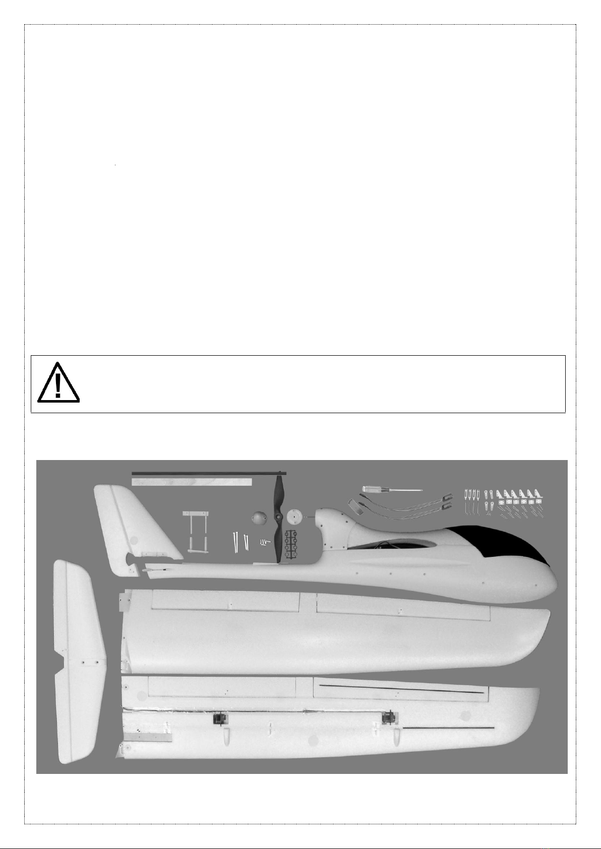
Lieferumfang:
Bitte kontrollieren Sie im Vorfeld ob der Lieferumfang vollständig ist.

Technische Daten:
Spannweite:
2000mm
Rumpflänge:
1044mm
Gewicht ohne Akku und Empfänger:
1100g
ESC / Motorregler:
30A Brushless
Motor:
1400kV Brushless Motor
Servos:
6x 9g
Akkuempfehlung
11.1V (3S) ab 1800mAh LiPo 25C (nicht enthalten)
Montage
Stellen Sie bitte bei der Montage sicher, dass Sie die richtigen Schrauben (Länge beachten) verwenden. Siehe auf
der ersten Seite der Anleitung.
Für den Aufbau benötigen Sie einen Kreuzschraubendreher und eine Zange.
1. Servogestänge Montage für Tragflächen / Höhen- und Seitenruder
Benötige Teile:
-Tragflächen Links und Rechts
- Höhen- und Seitenruder
- 6x Servogestänge inkl. Gabelköpfe
- 6x Ruderhörner und Gegenplatte
- 12x Schrauben (13x2mm)
Schieben Sie die Servogestänge in die passenden Löcher der jeweiligen Servohörner.
Montieren Sie die Ruderhörner und die Gegenplatte mit jeweils 2 Schrauben (15x2mm) in die Aussparungen auf der
Unterseite der Tragflächen.
Verbinden Sie die Gabelköpfe mit den Ruderhörnern.

2. Einsetzen des Höhenleitwerks
Benötige Teile:
- unterer Rumpfeinsatz
- oberer Rumpfeinsatz (Seitenruder Halter)
- Höhenleitwerk
- 2x Schrauben (16x2mm)
Stecken Sie den unteren Rumpfeinsatz in den Rumpf, achten Sie bitte auf die passende Wölbung. Die beiden Enden
des Rumpfeinsatzes müssen oben aus dem Rumpf heraus stehen.
Stecken Sie das Höhenleitwerk auf den Rumpf auf.
Achten Sie darauf, dass die kurze Aussparung des oberen Rumpfeinsatz zum Motor zeigt.
Fixieren Sie das Höhenleitwerk mit 2 Schrauben
(16x2mm)
3. Einbau des Seitenleitwerks
Benötige Teile:
- Seitenleitwerk
- 2x Schrauben (20x2mm)
Stecken Sie das Seitenleitwerk in die dafür vorgesehene
Aussparung (oberer Rumpfeinsatz). Fixieren Sie das
Seitenleitwerk mit den Schrauben (20x2mm).
Führen Sie die Seitenrudermontagehalterung bis zum
Seitenleitwerk auf

4. Tragflächenmontage
Benötige Teile:
- linke und rechte Tragfläche
- Karbonrohr
- Holzverbinder
- 4x Schrauben (4x2mm)
Markieren Sie die Mitte des Karbonrohrs. Schieben Sie das Rohr gleichmäßig in die dafür vorgesehen Löcher der
Tragflächen, so dass in beiden Tragflächen das Rohr gleichmäßig steckt. Ggf. in einer der Tragflächen mit etwas
Klebstoff fixieren.
Führen Sie die Tragflächen auf der Oberseite liegend (siehe Bild rechts) zusammen. Achten Sie darauf, dass die
Servokabel auf der Unterseite der Tragflächen verbleiben.
Legen Sie den Holzverbinder in die Aussparung auf der
Unterseite der Tragflächen. Fixieren Sie diesen mit den 4
Schrauben (4x2mm).
5. Servokabel der Tragflächen
Benötige Teile:
- 2x Servo Y-Kabel
Verlängern Sie die Servokabel der jeweiligen Ruder der
Tragflächen mit einem Y-Kabel. Achten Sie darauf, das
Sie die gleichen Ruder
(linkes Querruder = rechtes Querruder) der linken und
rechten Tragfläche mit dem Y-Kabel verbinden. Siehe
Markierung auf den Servokabeln.
Bei Verwendung einner Computer-RC Fernsteuerung
mit min. 7 Kanälen kann auf die beiden Y-Kabel
verzichet werden. Jedes Servokabel wird dann dem
entsprechenden Empfänger-Kanal zugewiesen. Sie
können dann jedes Servo trimmen und die Querruder
differenzieren.

6. Montage der Tragfläche auf dem Rumpf
Benötige Teile:
- montierte Tragflächen
- 2 St. Schrauben vorne (35x3mm)
- 2 St. Schrauben hinten (25x3mm)
Schließen Sie im Vorfeld die Servokabel gemäß der
Anleitung RC-Anleitung an die zugehörigen
Empfängerausgänge an.
Führen Sie die Servokabel durch die Aussparung für die
die Tragflächen in den Rumpf ein. Schieben Sie die
Tragflächen auf. Fixieren Sie diese mit den 4 Schrauben.
7.Aufstecken der Rumpfabdeckung und Haube
Benötige Teile:
- vordere Rumpfabdeckung
- Haube
Führen Sie die vordere Rumpfabdeckung in die Aussparung am Motorträger ein. Fixieren Sie die Abdeckung mit dem
Verschluss an der Rumpfnase. Stecken Sie die Haube in die dafür vorgesehenen Öffnungen.

8. Montage des Propellers
Benötige Teile:
- 1x Stoppmutter und 1x Mutter (bereits auf der Motorwelle)
- 1x Unterlegscheibe
- Spinnerrückplatte
- Propeller (inkl. Adapterringe)
- Spinnerkappe
- 2x Schrauben (7,5x2,6mm)
Stecken Sie die kleinsten Adapterringe (beidseitig) in die
Aufnahme vom Propeller.
Drehen Sie die Mutter bis zum Ende des Gewindes der
Motorwelle (in Richtung Motor). Stecken Sie die
Spinnerrückplatte auf die Motorwelle, achten Sie auf die
Aussparung der Rückplatte (Sechskant).
Schieben Sie den Propeller auf die Motorwelle auf.
!! ACHTEN SIE UNBEDINGT AUF DIE RICHTIGE
MONTAGERICHTUNG DES PROPELLER. DIE
BEZEICHNUNGEN AUF DEM PROPELLER ZEIGEN ZUM
MOTOR.
Fixieren Sie den Propeller mit der Unterlegscheibe und der
weiteren Stoppmutter auf der Motorwelle. Ziehen Sie die
Stoppmutter fest. Halten Sie hierzu die Spinnerrückplatte
von Hand fest.
Zum Abschluss stecken Sie Spinnerkappe auf die
Motorwelle und schrauben Sie diese mit den zwei
Schrauben (rechtes unteres Bild) fest.

Erstflug
Schließen Sie den Regler (ESC) und die Servos gemäß der Vorgabe des
Empfängerherstellers an.
Beachten Sie immer: Dass die Funktionen der Fernsteuerung, auch die Funktionen des Modells abdecken.
Beim Starten schalten Sie zuerst die Fernsteuerung ein und dann das Modell!
Beim Beenden schalten Sie zuerst das Modell aus und dann die Fernbedienung!
Der Schwerpunkt des Modells ist konstruktionsbedingt fest vorgegeben und liegt etwa 40 mm hinter der Flügelnase
bis zum Flugzeugmittelpunkt (gemessen in der Flächenmitte –sie Markierungen im Bild). Wenn das Modell rechts und
links von diesen Punkten angehoben wird, sollte es sich in der Waage befinden bzw. die Nase leicht nach unten
nehmen.
Durch Verschieben des Flugakkus oder durch Zugabe von Bleigewichten an der Rumpfspitze oder am Rumpfheck
kann der Schwerpunkt gegebenenfalls verlagert werden. Wird der Schwerpunkt weiter nach vorne verlegt, erhöht das
zwar die Stabilität, verschlechtert aber die Gleitflugeigenschaften des Modells. Wird der Schwerpunkt weiter nach
hinten verlegt, verbessert das zwar die Gleitflugeigenschaften, jedoch wird das Modell sehr instabil und reagiert
extrem heftig auf die Steuerbefehle des Höhenruders. Das Verschieben des Schwerpunktes empfehlen wir nur Piloten
mit ausreichend Erfahrung.
Stellen Sie sicher, dass die Querruder als auch die Wölbklappen bei Neutralstellung am Sender mit dem Modell
übereinstimmen. Falls dies mit der Trimmung des Senders nicht möglich ist, müssen die Gabelköpfe entsprechend
ein- oder ausgedreht werden.

Beachten!
Fliegen Sie dieses Modell nicht, wenn Sie noch keinerlei Erfahrung haben!
Junge Piloten sollten immer mit einem erfahrenen Piloten unter Aufsicht fliegen!
Fliegen Sie nur bei gutem Wetter! Stellen Sie die Wölbklappen
(ca. 50%) beim Start nach unten.
Bei geringem Wind ist der PeliCam am Einfachsten zu fliegen. Um Schäden
zu vermeiden, stoppen Sie das Fliegen bei starken Windgeschwindigkeit und
Böen. Stellen Sie sicher, dass niemand sonst auf Ihrer Frequenz fliegt.
Wählen Sie ein großes Gebiet (min. 300x300m) ohne jegliche Hindernisse
aus. Optimal ist eine freie Wiese.
Konzentrieren Sie sich beim Fliegen ausschließlich auf das Modell!
Suchen Sie bereits vor dem Flug einen passenden Landeplatz!
Starten Sie das Modell immer gegen den Wind.
Überprüfen Sie die Reichweite des Systems vor jedem Start. Stellen Sie
sicher, dass die Batterien/Akku in der Fernbedienung neu/geladen sind.
Achten Sie darauf, dass die Gasstellung der Fernsteuerung auf null steht,
bevor Sie die Fernsteuerung einschalten. Den entsprechenden Trimmer
ziehen Sie auch nach hinten –die Anderen in Mittelstellung. Schalten Sie
erst die Fernbedienung, dann das Modell ein.
Nehmen Sie sich einen Starthelfer, der das Elektromodell bei voller
Motorleistung mit einem sanften Schwung gegen den Wind frei gibt. Dabei ist
darauf zu achten, dass der Starthelfer beim Werfen nicht mit den Fingern in
den Propeller kommt.
Passen Sie den geraden Flug mit den Trimmern an. Gegenfalls können Sie diese Justierung über Ihre (Compuer-)
RC-Anlage durchführen und abspeichern. Lesen Sie bitte dazu die Anleitung Ihrer RC-Anlage durch.
Reparaturen
Der PeliCam ist zu großen Teilen aus EPP gefertigt (Expandiertes Polypropylen). Trotzdem kann das Modell bei
härteren Aufschlägen beschädigt werden.
Benutzen Sie unseren Spezial-Kleber „Blue Glue“ um Beschädigungen der Tragflächen zu beheben.
Ersatzteile sind bei Ihrem Händler oder unter www.air-ace.net erhältlich.
Bei Fragen wenden Sie sich bitte an unseren Service (Tel. +49 700 77 77 00 (12ct/Min.) oder
per Mail service@acme-online.de).

SECURITY ADVICES
The Pelicam Glider is not suitable for children under the age of 14 years. For under age use, parent’s supervision is -absolutely needed.
The operation with this Pelicam requires a middle level of technical knowledge as well as care and awareness in safety and acting.
Using the model under the influence of alcohol or drugs is strictly prohibited.
Never use close to traffic ways, nearby parks, schoolyards and playgrounds where you could meet unexpected obstacles.
Keep sufficient distance from traffic, rail traffic, airports, buildings and high voltage wires (minimum half a kilometer).
ATTENTION! The Pelicam Glider has a real fast rotating and powerful engine! Never try to touch the propeller while operating. Fingers
could be disembodied. As parts can come out because of crashes, we also advise you to keep the model away from your face while
battery is connected. Those parts can cause considerable injuries. Please kindly be aware of the danger zone and always keep
spectators far away from the model itself when flying. A safety clearance of at least 5 meters has to be observed. Always keep the
necessary distance to persons and obstacles –never cross those with a low height. Approach to the model just from the back.
Without motor speed the model is not controllable.
Before every start check your model, above all if being damaged because of former crash. NEVER start the model with one of those parts
damaged: battery, propeller, engine or steering. The functionality of the remote control has to be checked before every start.
Don´t run the model in brine or saline areas.
The use during temperatures between –5°C and 35°C is not recommendable.
Don´t use the model during bad weather: strong wind, rain...
The usage in areas of nature reserve, landscape reserve and water pollution control is prohibited.
In case of a damage just use original Pelicam Glider spares parts.
The model must be run with full charged transmitter batteries to provide the best range.
Pay attention that you will not interfere with other models using the same frequency. Don´t start the model if you are not sure that the
chosen frequency is free.
Note: ACME the game company is unable to ensure correct use according to these instructions. For this reason
ACME the game company will not accept any claim under guarantee.
Make sure that your insurance covers damages that may happened when using the model.
Sign a special R/C model insurance if necessary.
Make sure that your insurance covers any damage that may result from use of this model.
If necessary, take out a liability insurance for flight models.
Content of box:
Please check in advance whether the delivery is complete.

Technical Data:
Span:
2000mm
Body:
1044mm
Weight without battery and receiver:
1050g
ESC / Motor controller:
30A Brushless
Motor:
1400kV Brushless Motor
Servos:
6x 9g
Recommended battery:
11.1V (3S) 1800 - 4500 mAh LiPo (not included)
Assembling the model
Please make sure that you are using the right screws (consider the length). See the instructions on the first page.
For the setup you need- next to the included screw driver- a pair of pliers.
1. Servo linkage assembling for main wings / elevator and rudder
Required parts:
- Left and Right wing
- Elevator and rudder
- 6x servo linkages incl. clevis
- 6x Rudderhorn and counterpart
- 12x screws (13x2mm)
Slide the servo linkages in the matching holes of the servo horns.
Mount the rudder horns and the counterplate with 2 screws (15x2mm) in the recesses on the underside of the wings.
Connect the clevis with the aileron.

2. Inserting the elevator unit
Required parts:
- lower fuselage bit
- upper fuselage bit (rudder bracket)
- elevator unit
- 2x Screws (16x2mm)
Insert the lower fuselage bit in the fuselage, please pay attention to the matching vault. The two ends of the fuselage
bit must point above, out of the fuselage.
Put on the rudder mounting to the vertical tail. Fix the elevator unit with 2 screws. (16x2mm)
Insert the upper fuselage bit through the elevator unit in the lower fuselage bit.
Fix the elevator unit with 2 screws (16x2mm).
3. Assembling the vertical tail
Required parts:
- Vertical tail
- 2x Screws (20x2mm)
Insert the vertical tail in the provided notch (upper fuselage
bit). Fix the vertical tail with the screws (20x2mm).

4. Assembling the wings
Required parts:
- Left and Right Wings
- Carbon tube
- wooden connector
- 4x Screws (4x2mm)
Mark the middle of the carbon tube. Slide the tube smoothly in the provided holes of the wings. If needed, fix the tube
with glue in one of the wings.
Connect the wings twisted (right picture). Make sure that the servo cables remain on the bottom of the wings.
Insert the wooden connector on the notch on the bottom of
the wings. Fix it with the 4 screws (4x2mm).
5. Servocables of the wings
Required parts:
- 2x Servo Y-Cable
Extend the servo cables on the wings with the Y-
Cables. Pay attention to the marks on the cables.
If you use a Computer-RC with at least 7 channels you
don’t need the two y-cables.

6. Mounting the wings on the fuselage
Required parts:
- mounted wings
- 2x Screws ahead (35x2,5mm)
- 2x Screws at the back (25x2,5mm)
Connect the power cable in advance according to the
instruction manual of the corresponding RC-receiver
outputs.
Pull the servo cables through the notch. Put on the
wings. Fix them with 4 screws.
7.Attaching the fuselage cover
Required parts:
- front cover
- black cover
Insert the front cover in the recess underneath the motor holder. Fix the cover with the shutter on the nose. Put on the
black cover.

8. Mounting the propellers
Required parts:
- 1x female screws and 1x screws (already on the motor shaft)
- 1x washer
- backplate
- Propeller (incl. Adaptor rings)
- Spinner cap
- 2x srews (7,5x2,6mm)
Attach the smallest adaptor rings in the socket of both sides
of the propeller.
Turn the female screws till the end of the thread. Put the
backplate on the motor shaft.
Attach the propeller on the motor shaft.
!! MAKE SURE THAT YOU ARE ASSEMBLING THE
HELICOPTER IN THE CORRECT WAY. THE
DESCRIPTIONS ON THE PROPELLER MUST POINT TO
THE MOTOR.
Fix the propeller with the washer and the other female screw
on the motor shaft. Pull the female screw tight.
Finally attach the spinner cap on the motor shaft and fix it
with the screws.

First flight
Connect the controller (ESC) and the servos according to the specifications of
the receiver´s manufacturer.
Remember always: The functions of your remote control cover the functions of the model.
First switch on the remote control and then the model!
Switch off the model and then the remote!
Trim the model before every flight –this brings the best results.
First switch on the remote, set gas to zero and connect the LiPo battery.
The CG of the model with LiPo inserted is at 4cm behind the wings edge until the middle of the plane.
Make sure that the aileron balances the wings on both sides. If both ailerons prevent a deflection which cannot be
trimmed, you need to directly align the two servo arms.
If the model is raised right and left of this point, it should be in the balance, or take the nose slightly down. By moving
the flight battery, or by adding lead weights to the nose or the tail section the CG can be moved if necessary. The
focus will be moved further forward, which increases the stability, but deteriorates the glide characteristics of the
model. The focus will be moved further back, which improves the gliding properties, but the model is very unstable
and reacts very strongly to the control commands of the elevator.
Make sure that the aileron as well as the flaps correspond to the model when the TX is in neutral position. If this is not
possible with the trim of the controller, the clevis has to be turned on/off accordingly.
Attention!
Do not fly this model if you have no experience!
Young pilots should always fly under observation of an experienced flier!
Only fly at good weather conditions! Keep the flaps half down at start.
You will be most successful when there are only low winds. To prevent
damages, stop flying when wind goes up to 4 Beaufort. Make sure your
frequency is not in use by anybody else around you.
Select a wide area (300x300m min) without any obstacles.
Concentrate onto the model during the whole flight!
Keep in mind: higher grass can protect the model when you’ll have a hard
touch-down.
Model must be launched against the wind to start climbing in the air.
Check the range of the system before every start. Make sure that the
batteries inside the controller are new/charged.
Pull down the gas stick before you switch on the remote. Pull back the
corresponding trimmer and keep the others in middle position. Switch on the
remote first and then the model.
The model takes off after some meters at ¾ thrust. Align directional flight with
the trimmer. You can reduce the deflection of the rudder by pulling the bar
closer to the center of the servos. Take a start helper who throws the model
smoothly against the wind while the engine is running at full power. Make sure that
the thrower does not touch the propeller.
Adjust the directional flight with the trims. If applicable, you can do this adjustment with your RC, please check the
instructions of your RC for this.

Repairs
For the most part the PeliCam is made of EPP (Expanded Polypropylen), a material that is able to absorb crashes with
its flexibility.
Nevertheless the model can take damages from bigger crashes.
Use our special „Blue Glue“ to fix damages on the wings.
Spare parts are available at your dealer or www.air-ace.net.
If you have any questions pease contact our service (Tel. +49 700 77 77 00 (12ct/Min.) or
by mail service@acme-online.de).

CE - Declaration
Herewith we declare that this item is in accordance with the essential requirements and other relevant regulations of the directive 1999/5/EC. A
copy of the original declaration of conformity can be obtained at the following address.
Hiermit erklären wir das dieses Modell den grundlegenden Anforderungen und den anderen relevanten Vorschriften der Richtlinie 1999/5/EG
entspricht. Eine Kopie der Konformitätserklärung kann unter der nachfolgenden Adresse angefordert werden.
Par la présente, nous déclarons que ce modèle est en règle avec les directives européennes essentielles et autres régulations relevant de la
directive 1999/5/EC. Une copie de la Déclaration d’origine de conformité peut être obtenue à l’adresse suivante.
Noi dichiara che questo veicolo è conforme ai requisti essenziali e agli altri specifici regulamenti della derittiva 1999/5/EC. Copia della Dichiarazione
di Conformità originale può essere richiesta al seguente indirizzo.
Por la presente nosotros declaramos que este avión cumple con los requisitos esenciales y con el resto de la normativa relevante según la
directiva n° 1999/5/EC. Una copia de la Declaración de conformidad original puede ser obtenida en la siguiente dirección.
Hierbij verklaren wij dat deze auto voldoet aan de noodzakelijke eisen en andere relevante regelgevingen van de richtlijn 1999/5/EC. Kopien van de
originele verklaring van conformiteit kan verkregen worden bij:
Härmed deklarerar vi, att denna bil överensstämmer med de väsentliga krav och relevannta foreskrifter av direktiv 1999/5/EC. En kopia av originalet
av Declaration of Conformity kan rekvireras fran följande adress:
Täma tuote on direktiiven 1999/5/EC vaatimusten mukainen. Alkuperäset vaatimustenmukaisuus-asiakirjat ovat saatavilla:
Hermed erklaerer vi, at denne bil overensstemmelse med de pakraevet regelementer og i henhold til andre relevante regulativer ifolge direktiv
1999/5/EC. En kopi af den originale erklaering med de angivne regler kan rekvireres pa folgende adresse:
ACME the game company GmbH
Boikweg 24
33129 Delbrück –Germany
T: +49 700 70 77 77 00 (12ct/Min.)
F: +49 2944 97 383 48
E: service@acme-online.de
www.ACME-Online.de
WEEE-Reg.-Nr.: DE64989527
© copyright 2011 ACME the game company GmbH
Table of contents
Languages: