Acom ACOM 04AT User manual

1

1
Table of Contents
1. GENERAL.........................................................................................................................3
1.1 DESCRIPTION AND FUNCTION OF THE TUNER.....................................................................3
1.2 USER ASSISTANCE ........................................................................................................4
1.3 PACKAGE CONTENTS ....................................................................................................4
1.4 DISTINCTIVE FEATURES ................................................................................................4
1.5 SAFETY REQUIREMENTS AND DEFINITIONS.................................................................5
1.5.1 LIGHTNING PROTECTION WHEN THE TUNER IS INSTALLED IN A BUILDING ......... 7
1.5.2 LIGHTNING PROTECTION WHEN THE TUNER IS INSTALLED OUTDOORS ............. 8
1.5.3 ELECTRIC SAFETY PRECAUTIONS............................................................................ 9
1.5.4 GENERAL SAFETY PRECAUTIONS............................................................................ 9
2. TUNER INSTALLATION .............................................................................................................. 9
2.1 UNPACKING AND INSPECTION OF DELIVERED PACKAGE........................................... 11
2.2 POWER SUPPLY VOLTAGE .......................................................................................... 11
2.3 INSTALLATION AND CONNECTION FOR INDOOR OPERATION..................................... 11
2.4 INSTALLATION AND CONNECTION FOR OUTDOOR OPERATION .................................13
2.5 GROUNDING – ADDITIONAL INFORMATION ................................................................. 19
2.5.1 LIGHTNING PROTECTION GROUNDING .................................................................. 19
2.5.2 GROUNDING FOR PROTECTION FROM ELECTRIC SHOCK ....................................... 19
2.5.3 RADIO FREQUENCY GROUNDING OR COUNTERPOISE............................................. 20
2.6 CONNECTING RF CABLES – ADDITIONAL INFORMATION ............................................ 20
3. GETTING STARTED WITH THE ACOM 04AT ............................................................... 21
3.1 TURNING ON AND OFF...............................................................................................21
3.2 INDICATION, CONTROLS AND MENUS ......................................................................22
4. STARTING UP AND MAIN FUNCTIONS ....................................................................... 24
4.1 WHAT IS TUNING TYPE / RATE (SELECTIVITY DEGREE, SHARPNESS) .................. 24
4.1.1 SHARP........................................................................................................................ 26
4.1.2 REGULAR ................................................................................................................... 26
4.1.3 WIDE........................................................................................................................... 26
4.1.4 FIXED.......................................................................................................................... 26
4.2 TUNER ASSIGNMENT AND UNASSIGNMENT .............................................................26
4.3 TUNING MODES: FULL, QUICK AND BYPASS ............................................................27
4.4 QUICK TUNING AND NON-VOLATILE MEMORY.........................................................27
4.5 OPERATION IN BYPASS MODE ..................................................................................28
4.6 CHANGING FREQUENCIES AND ANTENNAS .............................................................29
4.7 SPECIFICS OF OPERATION IN TRANSMISSION MODE .............................................29

22
4.8 POWER REDUCTION AT OVERLOAD..........................................................................29
5. BASIC FULL TUNING CYCLE ......................................................................................30
5.1 WHAT A FULL TUNING CYCLE DOES .........................................................................30
5.2 OPERATOR ACTIONS FOR A FULL TUNING CYCLE ..................................................31
5.2.1 FULL TUNING FOR TRANSCEIVERS WITH CAT ........................................................... 31
5.2.2 FULL TUNING FOR TRANSCEIVERS WITHOUT CAT CAPABILITY............................. 31
6. ADVANCED FUNCTIONS AND OPTIONS OF THE TUNER..........................................32
6.1 ANTENNA ASSIGNMENT MENU .................................................................................32
6.1.1. ANTENNA ASSIGNMENTS BY BANDS ............................................................................ 33
6.1.2 SETTING THE TUNING TYPE / RATE (SHARPNESS, SELECTIVITY)
(S, R, W, F) ..................................................................................................................................... 33
6.1.3 EDITING ANTENNA NAMES.............................................................................................. 33
6.2 MAINTENANCE FUNCTIONS – ATU SERVICE MENU.................................................34
6.3 OVERVIEW OF TUNING SETTINGS AND RESOURCES USED .................................. 38
6.4 MEASUREMENTS IN THE TUNER – ATU MEASURE MENU ....................................... 39
7. MAINTENANCE ............................................................................................................41
7.1 CLEANING...................................................................................................................41
7.2 FUSE REPLACEMENT ................................................................................................41
7.3 ACOM 04AT BLOCK DIAGRAM AND PRINCIPLE OF OPERATION..............................41
7.4 TROUBLESHOOTING – MONITORING THE ANTENNA-FEEDER PATH STATUS ....... 45
8. SPECIFICATIONS.........................................................................................................47
8.1 PARAMETERS .............................................................................................................47
8.2 FUNCTIONS ................................................................................................................49
8.3 STORAGE AND TRANSPORTATION ...........................................................................50
APPENDIX 1 LIGHTNING PROTECTION.........................................................................52
9. DISCLAIMER ................................................................................................................55

3
1. GENERAL
1.1. DESCRIPTION AND FUNCTION OF THE TUNER
This operating manual covers the installation, operation, and maintenance of the remote
automatic antenna tuner for HF+6m with integrated four way antenna switch model
ACOM 04AT.
The ACOM 04AT tuner is specically designed and developed to work exclusively with
the ACOM series of transistor ampliers. It automatically selects one of four available
antenna outputs (as assigned in bands by the operator) and matches the impedance of
the chosen antenna output by transforming it to 50 Ohm with SWR below 1.5:1 at the
tuner input (typically below 1.3), providing an optimum load impedance for the amplier.
Any necessary readjustments are swift, following the frequency changes and antenna
selections.
The tuner matches all load impedances presenting a SWR below 3:1, regardless of
phase angle, in a continuous frequency range of 1.8 – 30 MHz and 50 – 54 MHz. In
many cases, the tuner will match loads with higher SWR (up to 10:1) as well, however
a reduction in power may be necessary if the protective functions of the tuner activate
due to high values of SWR, current, voltage, forward or reected power at the antenna
output.
Provided the SWR of the feedline/antenna system is up to 3:1, the tuner can handle input
power levels up to 1200W (PEP, mean or continuous carrier), regardless of the operating
communication mode. For feedline/antenna system SWRs between 3:1 and 10:1, the
maximum permissible power at the tuner input is gradually reduced down to 200W at
SWR=10:1 (Table 8.1), allowing for operation within tuner component specications.
The tuner can be installed both in the shack and in a remote location, e.g. in a separate
room, in a sheltered location outdoors or even out in the open, close to the antennas,
so that any feedlines from the unit to the antennas, working in mismatched conditions,
are kept as short as practically possible to avoid unnecessary losses.
Generally, a remote installation of the tuner is preferable to a local one, because it
reduces RF losses in most of the feedline’s length. Thanks to the built in automatic
antenna switch, a signicant reduction in both installation eort and required cable
length can be achieved (up to three times the feedline length with four antennas and
in-shack tuner installation).
A single cable connects the tuner to the radio station – the main coaxial feedline, which
is often already pre-installed. Tuner power supply, control and RF signals are combined
on the feedline, easing remote installation, lowering costs and uncluttering the shack.

44
Provided a low loss hi-quality cable is used (e.g. RG-213), the distance between the
tuner and the shack can be up to 100m (330ft). However, the length of the cable should
be kept at minimum to avoid any unnecessary losses, which exist in any cable even in
matched conditions.
NOTE
When tuner transportation is required, please use the orig-
inal packaging.
The wide operating temperature range of the tuner (-40 to +65oC), the single cable to
the shack, and the included accessories – all make for an easy outdoor installation.
However, if you have a choice of installation locations, you should always prefer one
that is sheltered from the elements. It will prolong the operational life of the tuner and
reduce material wear.
Regardless the choice of installation location, the operator is able to control and moni-
tor the tuner’s work via the amplier front panel using simplied and intuitive menus in
the original style of the ACOM transistor amplier series.
1.2. USER ASSISTANCE
If you need technical or other assistance, please call your local dealer rst. If you need
more information, you can contact ACOM directly at:
mail.orbitel.bg, or by mail to: Soa-Bozhurishte Economic Zone, 6 Valeri Petrov str,
2227 Bozhurishte, Bulgaria. Website: www.acom-bg.com.
1.3. PACKAGE CONTENTS
ACOM 04AT tuner, complete with Weather Protection Hood ACOM 04-WP, three sets
of installation accessories: ACOM 04-DT (desk), ACOM 04-WM (wall) and ACOM 04-
MM (mast), two fuse replacement sets and this Operating Manual will be delivered in
as a package.
1.4. DISTINCTIVE FEATURES
• Easy set-up of user tuning presets: for a CAT transceiver a single press of the
TUNE button on the amplier front panel is all you need.
• Transparent (invisible) operation: after setting up the user presets (auto tune)
for the frequency segments and antennas, the operator will not be involved with tuner
operation.
• Three kinds of frequency segments, according to antenna bandwidth: the op-
erator can choose according to the nature of each of the four antennas (narrow band
– Sharp, normal – Regular, and broad band – Wide).
• Capability of operation at xed frequencies (Fixed).
• Non-volatile memory for user presets (auto tune), independent for the four an-
tennas, the three types of segment width, and more than 1000 random xed frequen-
cies for each antenna.
• The user presets are automatically loaded, following frequency and antenna
selection changes.

5
• Export (backup) of preset memory to a computer le, import of previously
made backup les from a computer to the tuner memory.
• Information about the setting age, and alerts for settings that reach a certain
age, dened by the operator in 4 possible age levels.
• Power supply and control to the tuner, as well as status return from the tuner
are facilitated over the coaxial cable between the amplier and tuner, no need for ad-
ditional cables or special control signals from the transceiver (the availability of CAT
control from the transceiver will give further advantages to the setup).
• Improved electromagnetic compatibility: full tuning can be completed within
5s (typically 2-3s), at 25W at the tuner input and less than 6W at the antenna output;
quick tuning (from nonvolatile-memory presets) is completed in less than 0.05s with
zero emitted signals.
• Input SWR during full tuning cycles: below 2:1, preventing activation of trans-
ceiver PA protection.
• Input SWR after completing a tuning cycle – below 1.5:1 (typically below
1.3:1).
• Relays with gold-plated contacts for excellent receive characteristics.
• Relay switching will only take place when no RF current is owing, prevent-
ing contact arcing critical for preventing contact oxidation, surface melting and ma-
terial transfer (otherwise resulting in poor receiving performance) and to avoid any
unwanted widening of the spectrum of signals, emitted during the tuning cycle.
• Air-core coils (no magnetic materials) and high-quality NP0 (C0G) ceramic
capacitors usage throughout the matching circuit.
• Improves harmonic suppression – the matching network is a low-pass L lter.
• Saves space on the operating position - can be located up to 100m (330ft)
away from the shack.
• Allows remote installation, including outdoors, close to the antenna feed-
point, minimizing losses.
• Integrated four-way antenna switch – less coaxial cable, shorter unmatched
sections, less losses.
• Antennas can be automatically and manually switched from the amplier
front panel. The last used antenna selection is memorized.
• Indication and editing of names and types of antennas in editable freeform.
• Various protection mechanisms, including: antenna overvoltage, antenna
overcurrent, excessive power during operation and tuning, extreme temperatures and
power supply voltages, as well as relay hot-switching.
• Safe power supply voltage (26VDC).
• Bypass mode – all components of the matching network are excluded, allow-
ing direct operation of broadband antennas.
• Service menu, allowing analysis of the tuner status and review of the used
resource of coils and capacitors for all memorized and current tuning presets.
• Integrated lightning arrestor and bleeder resistor for protection against static
discharges; automatic grounding of antennas on powering down.
1.5. SAFETY REQUIREMENTS AND DEFINITIONS
The ACOM 04AT has been designed to comply with the international safety standards
and to comply with safety and electromagnetic compatibility regulations of the FCC
and European Union.

66
This manual contains information, warnings and instructions, related to hazards, that
should be followed by the user in order to ensure safe operation and to keep the tuner
in a safe working condition at all times.
Warnings:
The explicit denitions described below apply to this operating manual:
WARNING HIGH VOLTAGE - These signs draw attention to procedures, which, if not
correctly performed, may result in injury, re hazard, and electric or lightning shock.
CAUTION - These signs draw attention to procedures which, if not correctly performed,
may result in equipment damage, not exclusively to the tuner but also to connected
equipment.
NOTE - These signs draw attention to procedures which, if not correctly performed,
could result in inconvenience.
WARNING HIGH VOLTAGE
For details about lightning protection see Appendix 1
at the end of this manual.
WARNING HIGH VOLTAGE
For safe tuner operation, the tuner’s grounding terminal la-
beled GROUND should be connected according to the ap-
plicable standards and local regulations for electric safety,
re safety and lightning protection, in all cases the radio
station is equipped with outdoor antenna/s!
WARNING HIGH VOLTAGE
Never run cables into the radio station directly from outside
(through a wall or window), whether from antennas, tun-
ers, groundings, telephone or network lines, etc. The ca-
bles should rst pass trhough the foundation of the building
where they should be secured in a way that is standard for
your region (observe the recommendations stated in Ap-
pendix 1 at the end of this manual, if no other data is avail-
able), in order to avoid conduction of a lightning strike with
all resulting consequences – death, injury, re, equipment
damage, destruction, etc. (Appx.1-8).
WARNING HIGH VOLTAGE
Regardless of the recommendations herein, it is your re-
sponsibility to consult a professional electrician for advice
on installing your grounding system, and to refer to, togeth-
er with the electrician, the applicable standards and local
regulations for electric safety, re safety and lightning pro-
tection, in all cases the radio station is equipped with

7
outdoor antenna/s, in order to ensure that your installation
complies with all applicable requirements. The applicable
standards and local regulations shall prevail if there is
a dierence in the requirements, and if they contain more
or stricter requirements than the minimum for installation
stated in Appendix 1. NEVER underestimate the danger
of lightning!
1.5.1 Lightning protection when the tuner is installed in a building
WARNING HIGH VOLTAGE
For details about lightning protection see Appendix 1
at the end of this manual.
1.5.1.1 The tuner’s terminal labeled GROUND
should be connected through a low-impedance connection with a cross section of
no less than 20 sq. mm (preferably at-shaped and solid – band or plate, rather than
with a exible multistrand cable), to the main grounding plate of the radio station
(Appx.1-9).
1.5.1.2 The antennas
should be connected by coaxial cables buried in the ground (when coming in from the
eld) or securely attached to the wall of the building (when coming down from the roof),
all along the route from the antennas to the foundation of the building where, before
entering, are discharged from the lightning charges in a safe way – directly into the
ground. For this purpose, the braids of the coaxial cables should be securely ground-
ed by a low-impedance connection to the main grounding plate of the building
(Appx.1-8).
1.5.1.3 From a low point close to the foundation of the building,
before going up to the radio station, the wires of the antenna cables should be equipped
with pulse overvoltage limiters (surge arresters), the grounding terminals of which
should be connected through a low-impedance connection to the main grounding
plate of the building (Appx.1-8).
WARNING HIGH VOLTAGE
When installing the tuner in the shack, do not connect an-
tenna cables to the tuner if they are entering the building
directly, without being grounded through a low-impedance
connection to the main grounding plate of the building!
Properly grounded antennas shall be guided to the shack
from the inside and from below, from the foundation of the
building and its main grounding plate rather than directly
from outside! (Appx.1-8).

88
1.5.2 Lightning protection when the tuner is installed outdoors
WARNING HIGH VOLTAGE
For details about lightning protection see Appendix 1
at the end of this manual.
When installed on a roof or in the eld, the tuner and antennas, if not provided with a
separate lightning protection, should be within the protection range of an existing light-
ning protection system.
Checking the eciency range of a lightning rod is performed using the method known
as “rolling sphere”.
If the tuner and/or the antennas are not protected by an existing lightning protection
system, the system should be extended, its range of action should be increased or a
new lightning protection system should be built, with a sucient range of action and
in compliance with all requirements of the local standards and regulations for electric
safety, re safety, and lightning protection.
1.5.2.1 The tuner’s terminal labeled GROUND
should be connected through a low-impedance connection (preferably at-shaped)
with a solid cross section of no less than 20 sq. mm to the closest (at a distance less
than 6m) main conductor from an existing grounding system for lightning protec-
tion, and where there is no such system, to a purpose-built individual low-impedance
grounding system for lightning protection, driven or buried directly in the ground
and in compliance with all requirements of the local standards and regulations for elec-
tric safety, re safety, and lightning protection (Appx.1-7).
1.5.2.2 The braids of the antenna coax cables
should be connected through a low-impedance connection (preferably at-shaped) with
a solid cross section of no less than 20 sq. mm to the same grounding system for
lightning protection, to which the tuner is connected, but with independent connec-
tions, i.e. the connections of the coaxial braids to the grounding system for lightning
protection should not be broken in case the tuner is temporarily removed (e.g. for main-
tenance).
1.5.2.3 Before the antenna cables are laid to the tuner,
they should be equipped with pulse overvoltage limiters (surge arresters), the ground-
ing terminals of which should be connected in the same manner as the braids in section
1.5.2.2.
1.5.2.4 The feedline between the shack and a remotely located tuner
should be coaxial cable buried in the ground (when coming from the eld) or securely
attached to the wall of the building (when coming down from the roof), all along the
route from the antennas to the foundation of the building. At the foundation, the braid
of this cable should be securely grounded at ground level and just before entering the
building, through a low-impedance connection (preferably at-shaped) with solid sec-
tion of no less than 20 sq. mm to the main grounding plate of the building (Appx.1-8).

9
1.5.2.5 At the place of entering the building,
before going further to the radio station, the feedline between the amplier and tuner
input should be equipped with a pulse overvoltage limiter (surge arrester), the ground-
ing terminal of which should be connected through a low-impedance connection to
the main grounding plate of the building (Appx.1-8).
1.5.3 Electric Safety Precautions
WARNING HIGH VOLTAGE
The electronics inside the tuner operate under high di-
rect-current voltage up to 200V, which is fatal! Never allow
anyone, especially children, to insert any object into box
holes – this may cause electric shock. Disconnect all ca-
bles from the tuner and every time wait at least 1 minute
before opening it!
WARNING HIGH VOLTAGE
RF voltage at antenna feedpoint and elements may exceed
several thousand volts! Never touch the antenna or an-
tenna isolators during transmission and tuning – this may
cause deep RF burns as well as indirect traumas, such as
falling!
1.5.4 General Safety Precautions
WARNING HIGH VOLTAGE
Do not undertake any repair or alteration in the design or
software of the tuner by yourself, as this may threaten your
or someone else’s health and life, or damage the tuner or
connected equipment, which is not covered by the warran-
ty.
CAUTION
To prevent damages not covered by the warranty, read
carefully Section 2, TUNER INSTALLATION, in this Oper-
ating Manual. Should you have any doubts related to in-
stallation, your safety during operation or tuner reliability,
please contact your local ACOM dealer rst. See S. 1.2 for
ACOM contact information.
2. TUNER INSTALLATION
The tuner can be installed at a xed site (in a room), under a shelter or outdoors – with
a special set of installation accessories for desks, walls or masts.
1010
WARNING
Never operate the tuner with its cover removed! Touching
the components inside the tuner while transmitting may re-
sult in RF burns and injury.
Mount/place the tuner so that the antenna terminals are not
accessible during operation.
Do not mount the tuner in a position that will put it under
water at any time.
Do not mount the tuner in a place that will allow sprinklers
or water hoses to spray the weather seals or connectors.
CAUTION
Do not try to additional weather sealing to the tuner. It
should be installed in an airy location in order to cool down
during operation and to dry up after rain or morning dew!
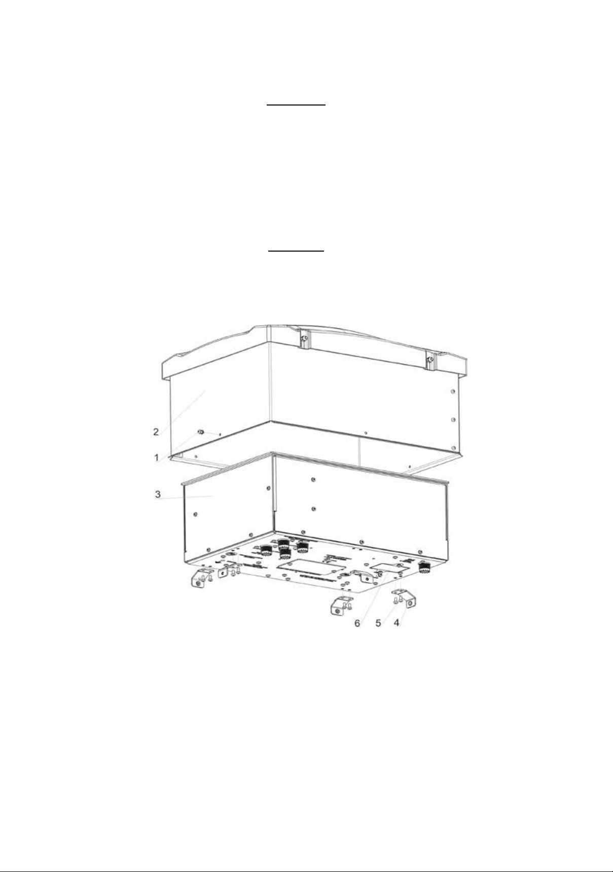
Fig. 2-1. ACOM 04AT tuner, with the ACOM 04-WP
weather protection cover removed, and without installation
accessories
Your new ACOM 04AT will be shipped with the protective cover mounted. Regardless
of which mounting option will be chosen (desk, wall or mast), in order to mount the
selected bracket, the weather protection cover must be removed (Fig. 2-1).

11
The cover (2) is xed to the tuner body (3) with 5 mounting brackets (4). Place the tun-
er on a at leveled surface with connectors facing down. Unscrew the 5 bolts (1) and
carefully lift the weather protection cover o the tuner body. If the tuner will be desk
mounted, the weather cover (2) and mounting brackets (4) should be safely stored.
The mounting brackets (4) are removed by placing the tuner with the connectors facing
up and unscrewing the 10 bolts (5), holding the brackets. If the tuner will be mast or
wall mounted, the weather protective cover (2) will be reassembled after mounting the
selected mast or wall bracket.
2.1 UNPACKING AND INSPECTION OF DELIVERED PACKAGE
NOTE
Before undertaking tuner installation, read this manual
thoroughly.
Upon shipment arrival carefully inspect the shipped cartons for mechanical damage.
Remove all contents from the cartons and inspect the tuner chassis and all installation
accessories for any missing items according to the order, as well as for any transpor-
tation damages. If you notice anything missing or damaged, immediately notify your
ACOM dealer. Any delay may void the warranty of the carrier.
Store safely the unused accessories and entire packing for possible future use or
transportation.
2.2 POWER SUPPLY VOLTAGE
The tuner is powered by direct-current voltage +26VDC +10/-15%, supplied through
the coaxial cable from the ACOM amplier RF output to the RF input of the tuner, la-
beled 50 Ohm RF +26VDC POWER & CONTROL.
CAUTION
In order to avoid any damage (not covered by the war-
ranty), never connect the input jack of the tuner, labeled
50 Ohm RF+26VDC POWER & CONTROL to any power
source except the output of an amplier from the ACOM
transistor series.
2.3 INSTALLATION AND CONNECTION FOR INDOOR OPERATION
NOTE
For installation and connection for remote / outdoor opera-
tion see S. 2.4.
If the desk mounting option is chosen, the tuner is placed on the desk with the
connectors facing to the back, rubber feet facing down and secured in place with the
provided desk bracket (Fig. 2-2). The decorative black anodized aluminum faceplate
provides an aesthetic look, matching any high-end ham radio setup.
1212
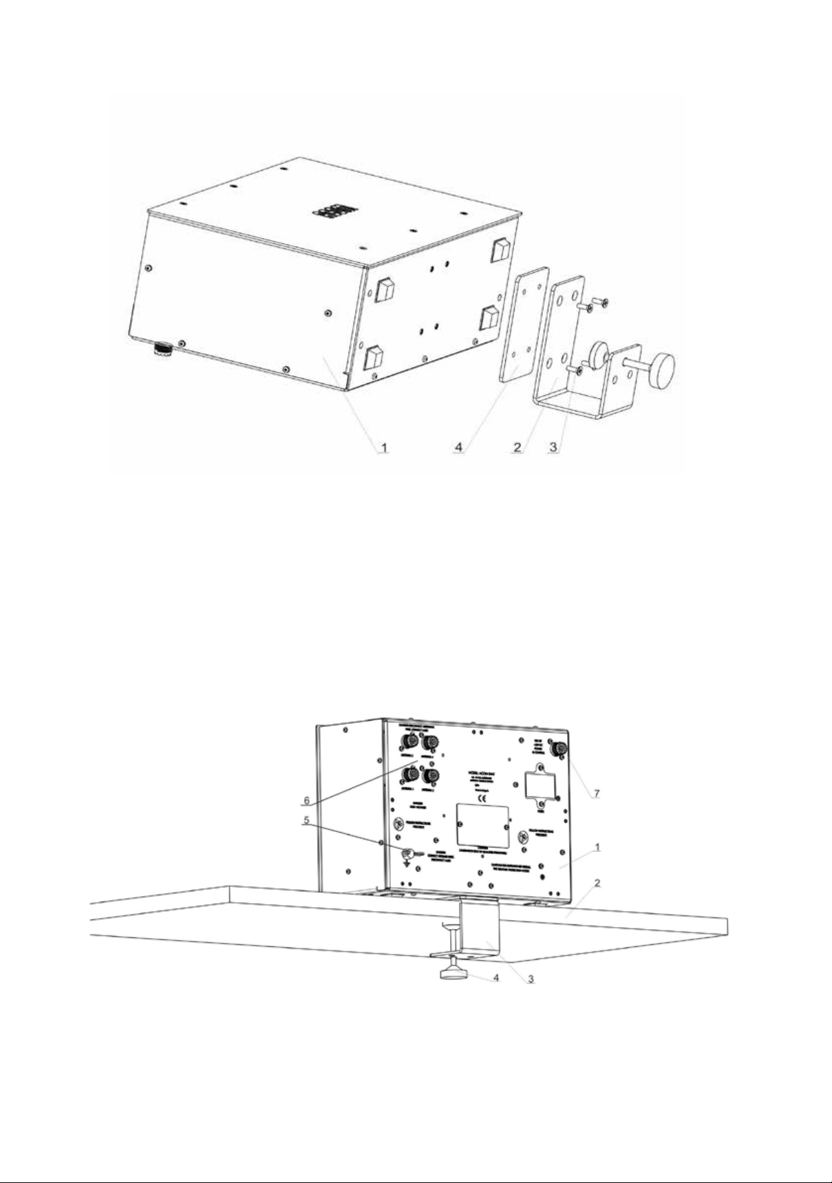
Fig. 2-2. Desk installation bracket
The desk bracket (2) is secured to the tuner body (1) via 4 at-head bolts (3) - Fig. 2-2.
Be sure to place the provided metal spacer plate (4) between the bracket and the tuner
body. The bracket is nished o with black polymer paint, reducing the possibility of ac-
cidental scratching of the desk surface.
After mounting and securing the tuner to the desk, the only contact surfaces are the
rubber feet and rubber protector of the bracket bolt, ensuring scratch-free desk surface.
Fig. 2-3. Securing the ATU to a desk

13
After securing the tuner body (1) on the desk (2) by fastening the bracket bolt (4), the
bracket (3) remains hidden from sight – gure 2-3. This ensures both a tidy workspace
and the necessary stability of the tuner body together with up to 5 heavy coaxial cables
connected to the back side.
WARNING HIGH VOLTAGE
For INDOOR tuner operation, the grounding terminal of the
tuner labeled GROUND and the antenna feeders should be
connected as described in S. 1.5.1.
Check if the antenna cables and grounding system of your radio station are installed
as described in S. 1.5.1. Next, connect the grounding terminal (5) of the tuner labeled
GROUND (Fig. 2-3) to the main grounding plate of the radio station (appx.1-9).
After connecting the grounding terminal, connect the antenna feeders (up to 4 coaxial
cables) to the respective connectors (6) ANTENNA 1 through 4 on the tuner (Fig. 2-3).
Without powering up the amplier, use a coaxial cable to connect the tuner HF input (7)
labeled 50Ohm RF +26 VDC POWER & CONTROL (Fig.2-3) to the ACOM transistor
ampliers output labeled RF OUTPUT.
2.4 INSTALLATION AND CONNECTION FOR OUTDOOR OPERATION
The wall and tower mounting brackets, provided with your tuner, allow the tuner to be
remotely mounted, reducing losses, installation costs and installation complexity. This
option should always be preferred if applicable. Remote operation drastically reduces
feedline losses, resulting from operating a mismatched coaxial line, leaving only the
inherent losses of the cable, operated in a source-feedline-load matched mode.
NOTE
For installation and connection for indoor operation see S.
2.3.
NOTE
Before commencing tuner installation, carefully consider
and map out the way the coaxial cables run from the ampli-
er to the tuner and from the tuner to the antennas, as well
as the manner in which they will enter the shack.
WARNING HIGH VOLTAGE
To prevent accidents, tuner installation and connection to
the grounding and antennas should only be carried out in
clear, quiet and sunny weather, when there is no danger
of lightning and static discharges.
Life threatening voltages and electrostatic charges may occur in the antenna and the
cables you install, both as a result of a direct lightning strike or by induction after a light-
ning strike on adjacent objects, and may also be statically induced by charged clouds
or energized by dust storms!

1414
WARNING HIGH VOLTAGE
Do not commence tuner installation if you don’t have a se-
cure lightning protection grounding system as per S. 1.5.2.
Do not use grounding systems that aren’t built to reg-
ulations – this may lead to re, gas explosion, other inci-
dents or death, including that of other persons. Never use
the tuner, unless it is properly grounded!
At rst, lay out the cables along the route to the radio station and antennas, and pro-
tect them from mechanical damage, in case they move in the wind, snow or ice. When
the end of the cable is inserted in the foundation of the building, take precautions to
seal against wetting the connecting terminals, main grounding plate of the building
(appx.1-8) or other connections thereof. As a minimum, leave a sucient U-shaped
slack before cable insertion to facilitate water dripo.
At the selected location install an appropriate set of installation accessories (ACOM
04-WM for walls or ACOM 04-MM for masts), as described hereafter. Do not install the
protection cover at this point.
The tuner should be mounted strictly horizontally, with the connectors facing down-
wards and at a height of no less than 1m above base level (ground or roof).
The installation height above the base is essential in order to install cables with a suf-
cient U-shaped slack under the tuner bottom level, so that any rain, dew and other
precipitation or sprays reected from base will not wet the tuner and will safely dripo.
Also, in the case of heavy snowfall, the snow will not reach the tuner connectors.
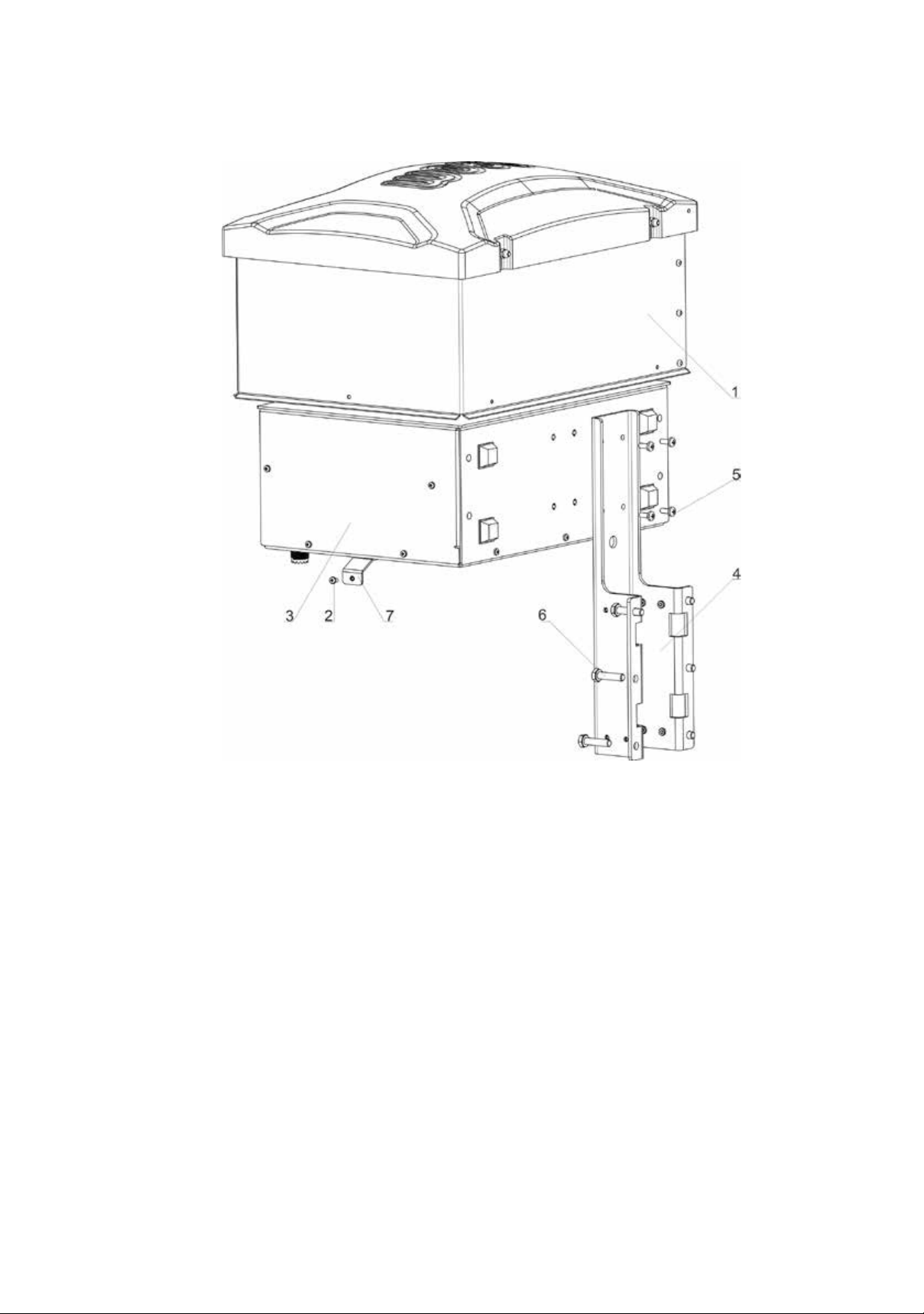
2.4.1 If the wall mounting option is chosen – Fig.2-4
The protective cover (1) is removed by unscrewing the ve bolts (2). The ve cover
holding brackets (7) are left in place, attached to the tuner body. Using the provided in
the mounting kit four at-head bolts (5), the wall bracket (4) is secured to the tuner body
(3) and then the protective cover (1) is secured back in place with the ve bolts (2).
15
Fig. 2-4. Wall installation bracket
The whole assembly (1 & 2) is then secured to a wall with 6 bolts (3) with the weath-
er protective cover facing up – gure 2-5. Although the weather protective cover (1)
provides the necessary shielding from the elements, whenever it’s possible, the tuner
should be mounted under a shed. This way maximum protection and minimum mate-
rial wear both from water and sunlight and heat will be provided, extending the tuner’s
operational lifespan. When installing the system outdoors always select a location,
free from any possible loose cables or other objects that might fall on or hit the tuner
assembly.
1616
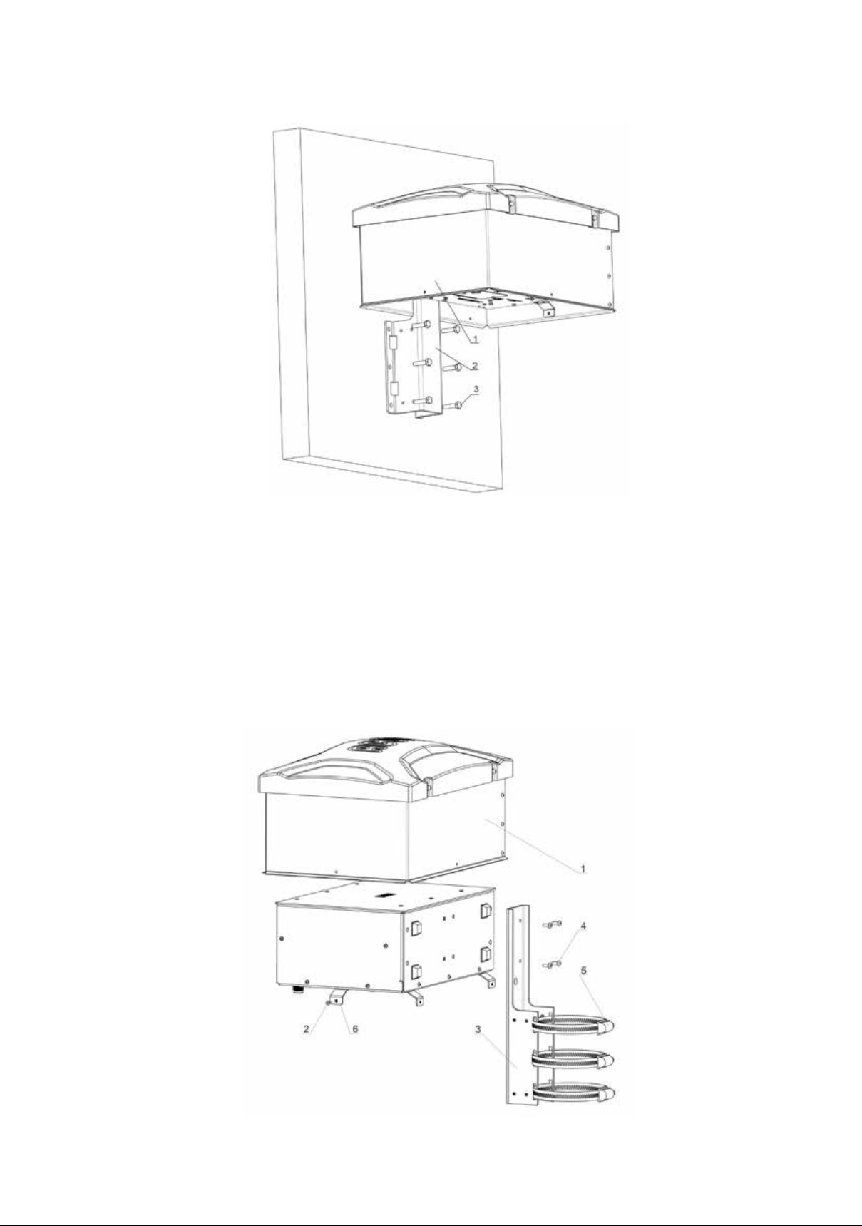
Fig. 2-5. ATU installed on a wall
2.4.2. If the mast mounting option is chosen – gures 2-6 & 2-7
The weather protective cover (1) is removed by unscrewing the ve bolts (2). The
ve cover holding brackets (6) are left in place, attached to the tuner body. Using the
provided in the mounting kit four at-head bolts (4), the mast bracket (3) is secured to the
tuner body and then the weather protective cover (1) is secured back in place with the
ve bolts (2).
Thread the three hose clamps (5), provided with the mounting kit, through their respective
rectangle opening pairs in the mast bracket (3).
Fig. 2-6. Mast installation bracket

17
The whole assembly – gure 2-7 (1 & 2) is then secured to the mast with the connec-
tors facing down using three hose clamps (3). Always secure any loose cables, guy
wires or any other object that might fall on or hit the tuner assembly.
Both mast and wall brackets have mounting holes for securing cables with the provid-
ed cable clamps (pos. 3 in the item list). The cable clamps are mounted with bolts (pos.
11) and a combination of 2 washers (pos. 10 and 13).
Finally, slip the Weather Protection Cover ACOM 04-WP over the tuner – gures 2-4
to 2-7, (1) - directing it with the protruding part (marked with ACOM) up. Place it
over the provided four carrying pins protruding from the tuner chassis. Carefully align
the protection hood until the pins t into the respective holes; the cover will go down a
bit and will rest on the ve carrying plates in the tuner base. Check whether all walls
of the protection hood are equidistant from the tuner chassis and whether their bottom
edges are parallel.
Use the provided xing elements in the installation kit to x the protection hood secure-
ly in place. Loosely screw all nuts and screws at rst, then fasten them tightly.
Fig. 2-7. Securing the ATU to a mast

1818
CAUTION
When mounting in the open, never install the tuner in a
slanted position neither with protection hood down, to avoid
contaminating the inside of the assembly, and to prevent
precipitation from seeping into it. This may cause damage
that is not covered by the warranty!
WARNING HIGH VOLTAGE
For remote / outdoor tuner operation, the grounding termi-
nal of the tuner marked GROUND, and the antenna feed-
ers should be connected as described in S. 1.5.2.
CAUTION
After completing the tuner installation, attaching, and con-
necting the cables, check the reliability of all xtures and
fasten again, if necessary. Apply mineral jelly or another
suitable lubricant to the connectors, grounding terminal,
and assembling nuts and screws to prevent jamming/
clinching or damage to the threads in a future disassembly.
LIST OF ACCESSORIES
Nr. ITEM PCS
1Mast Bracket 1
2Desk Bracket 1
3Cable clamps 5
4Desk Bracket Bolt 1
5Desk Bracket Bolt Threaded Pad 1
6Hose Clamp - small 3
7Desk Bracket Spacer Plate 1
8Wall Bracket 1
9Hose Clamp - large 3
10 Washer (DIN6798-A4.3-A2) - mounting pos. 1, 8 and 3 (together with 13) 10
11 Bolt (DIN7985-M4x10-A2) - mounting pos. 1, 8 and 3 (together with 13) 10
12 Flat-Head Bolt (DIN965-M4x12-A2) 4
13 Washer (DIN9021-M4-A2) - mounting pos. 3 (together with 10 and 11) 5

19
Fig. 2-8. Accessories
2.5 GROUNDING – ADDITIONAL INFORMATION
Ground the tuner and install the cables from the antennas and from the tuner obeying
safety requirements in S. 1.5. You need to distinguish between dierent kinds of
grounding according to its function!
2.5.1 LIGHTNING PROTECTION GROUNDING
See the instructions provided in S. 1.5 and Appendix 1. This kind of grounding is used
for lightning protection of people, buildings and equipment, but does not protect
you from voltages or currents with mains frequency or emitted/induced RF signals.
2.5.2 GROUNDING FOR PROTECTION FROM ELECTRIC SHOCK
This grounding (or neutralizing in some cases) is used for protection from electric shock
from currents with mains frequency. It will not protect you from a possible lightning or
emitted/induced RF signals.
To ensure that your installation complies with the requirements consult a qualied elec-
trician to nd out if simultaneous grounding and neutralizing, according to the rec-
ommendations of S. 1.5, is allowed by the applicable standards and local regulations
for electric shock protection.
Table of contents
Other Acom Tuner manuals


